
ZIEHL industrie – elektronik GmbH + Co KG
Daimlerstraße 13, D – 74523 Schwäbisch Hall
+ 49 791 504-0, in[email protected], www.ziehl.de
Temperature Relays and MINIKA® Mains Monitoring Digital Panelmeters MINIPAN® Switching Relays and Controls Measuring Transducers Grid- and Plant Protection
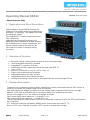
Operating Manual DRR10
updated: 2015-12-10/Fu
DRR10 11770-0701-00 Page
1
/ 4 www.ziehl.de
- Phase-Sequence Relay
1 Application and Short Description
Phase-sequence relays DRR10 measure the
sequence of the phases when being switched on
and switch - if necessary - the rotation of the field
by changing 2 phases.
The integrated PTC-monitor protects the motor
from overheating.
Applications are especially machines and
equipment, that is operated at variable locations
e.g. at building sites. Pumps, compressors and
vacuum cleaners always run correctly. No
more search for faults or change of wiring
necessary.
2 Overview of Function
automatic change of wrong phase-sequence when connected falsely
running backward of motors is avoided
integrated PTC-protection for motor
enable-input for direct switching on/off of the motor with DRR 10
max. 3 x 12 A
switch-on currents 30 A / max. 4 s / 60 A / max. 1 s
higher currents with external contactors
integrated protection for relay contacts
integrated protection from over-temperature
housing for mounting in fuse-boxes or switchgearcabinets, mounting height 55 mm
3 Detailed Description
The device can be switched on and off with a potential-free contact at the enable-input (E1/E2). When no
contact is connected, an isolated bridge has to be mounted.
After switching on the voltage, the sequence of the rotatory field is measured. When there is a bridge
between Y1/Y2, after a short delay the correct phase-sequence is available at the output.
If there is no bridge in Y1/Y2, the output is connected as follows:
Input correct (right) phase-sequence --> Output 2/T1 = L1
Input wrong (left) phase-sequence --> Output 4/T2 = L1
Thus for big motors the phase-sequence can be corrected with contactors at 2/T1 and 4/T2 (see Examples
for Connection).
PTC-sensors according to DIN 44081 / 44082 can be connected to the inputs T1, T2.
When no PTCs are connected, the inputs T1/T2 have to be shorted with a bridge.

DRR10 11770-0701-00 Seite
2
/ 4 www.ziehl.de
4 Important Notes
WARNING
Dangerous electrical voltage!
May lead to electrical shock and burn.
Before beginning of work switch unit and equipment free of voltage.
To use the equipment flawless and safe, transport and store properly, install and start professionally and
operate as directed.
Only let persons work with the equipment who are familiar with installation, start and use and who have
appropriate qualification corresponding to their function. They must observe the contents of the
instructions manual, the information which are written on theequipment and the relevant security
instructions for the setting up and the use of electrical units.
The equipments are built according to DIN / EN and checked and leave the plant according to security
in perfect condition. To keep this condition, observe the security instructions with the headline „Attention“
written in the instructions manual. Ignoring of the security instructions may lead to death, physical injury
or damage of the equipment itself and of other apparatus and equipment.
If, in any case the information in the instructions manual is not sufficient, please contact our company or
the responsible representative.
Instead of the industrial norms and regulations written in this instructions manual valid for Europe, you
must observe out of their geographical scope the valid and relevant regulations of the corresponding
country.
Observe the maximum temperature permissible when installing in switching cabinet. Make shure
sufficient space to other equipment or heat sources. If the cooling becomes more difficult e.g.
through close proximity of apparatus with elevated surface temperature or hindrance of the
cooling air, the tolerable environmental temperature is diminishing.
5 Mounting
• mount on 35 mm mounting rail according to EN 60715
• wall-mount with 2 x screws M4
• connecting wires refer to the wiring diagram to prevent miss-operation and malfunction.
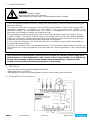
6 Examples for Connection

DRR10 11770-0701-00 Seite
3
/ 4 www.ziehl.de
ATTENTION! E1, E2, Y1, Y2, T1, T2 not potentially separated,
use insulated bridges and cables only !
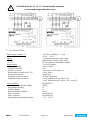
7 Technical Data
Rated supply voltage Us: 3 AC 400 V, 50/60 Hz < 3 VA
Tolerance +10 % ... -20 %
Inputs: no potential separation from supply
E1, E2 potential-free contact for AC 400 V
T1, T2 PTC according to DIN 44081 / 44082
Output relays: 2 x 2 NO-contacts
Switching voltage max. AC 440 V
Thermal current Ith 12 A
Switch-on current 30 A max. 4 s / 60 A max. 1 s
Rated nominal current Ie (AC 15) 3 A AC 400 V
Recommended fuse gG/gL 16 A
Expected contact life mech. 30 x 10
6
operations
Expected contact life electr. 1 x 10
6
operations at AC 400 V / 3 A
2 x 10
5
operations at AC 400 V / 6 A cos φ 0,5
Test conditions: EN 60255-27
Rated impulse withstand voltage 4000 V
Overvoltage category III
Pollution degree 2
Rated insulation voltage Ui 300 V
EMV - immunity EN 61000-6-2
EMV - emission EN 61000-6-3
Rated ambient temperature range - 20 ... + 55 °C
!

DRR10 11770-0701-00 Seite
4
/ 4 www.ziehl.de
Housing: Design V4
Mounting height 55 mm
Width 4 TE
Dimensions (B x H x D) 70 x 90 x 58 mm
Line connection 1 wire each 1 x 4 mm
2
Stranded wire with wire-end sleeves each 1 x 2.5 mm
2
Protection housing IP 30
Protection terminals IP 20
Mounting Snap mounting on 35 mm standard rail 35 mm
according to EN 60715 or with 2 screws M4
Weight app. 230 g
Subject to technical modifications
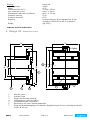
8 Design V4: dimensions in mm
1 Oberteil / cover
2 Unterteil / base
3 Riegel / bar for snap mounting
4 Plombenlasche / latch for sealing
5 Frontplatteneinsatz / front panel
6 Kennzeichen für unten / position downward
7 Riegel bei Wandbefestigung mit Schrauben. Riegelbohrung Ø 4,2 mm / for fixing to wall with
screws, Ø 4,2 mm.
48
58
45
3
61,8
16,5
(90)
Option
70
98
116
6
1
2
3
4
5
7
-
 1
1
-
 2
2
-
 3
3
-
 4
4


Ask a question and I''ll find the answer in the document
Finding information in a document is now easier with AI
Related papers
-
ZIEHL STWA1FH Operating instructions
-
-
-
-
-
-
-
-
-
