LG LT1030HR Owner's manual

Type
Owner's manual

This manual is also suitable for

G
ROOMAIR CONDITIONER
website http://www.lgapplian _
OWNER'S MANUAL
Please read the operating instructions and safety precautions carefully
and thoroughly before installing and operating your room air conditioner.
DEVENTANA
,o
FOR YOUR RECORDS
Write the model and serial numbers here:
Model #
Serial #
You can find them on a label on the side of each unit.
Dealer's Name
Date Purchased
[] Staple your receipt to this page in the event you need it
to prove date of purchase or for warranty issues.
READ THIS MANUAL
inside you will find many helpful hints on how to use and
maintain your air conditioner properly. Just a little preventive
care on your part can save you a great deal of time and
money over the life of your air conditioner.
You'll find many answers to common problems in the chart
of troubleshooting tips. if you review our chart of
Troubleshooting Tips first, you may not need to call for
service at all
PRECAUTION
®Contact the authorized service technician for repair
or maintenance of this unit.
, Contact the installer for installation of this unit.
=The air conditioner is not intended for use by young
children or invalids without supervision.
,Young children should be supervised to ensure that
they do not play with the sir conditioner.
• When the power cord is to be replaced, replacement
work shaft be performed by authorized personnel only
using only genuine replacement parts.
, Instaflation work must be performed in accordance
with the National Electric Code by qualified and
authorized personnel only.
2 Room Air Conditioner
SafetyPrecautions
To prevent injury to the user or other people and property damage, the following instructions
must be followed.
m Incorrect operation due to ignoring instruction will cause harm or damage. The seriousness
is classified by the following indications.
,WARNING This symbol indicates the possibility of death or serious injury.
CAUTION This symbolindicatesthe possibilityof injury or damageto propertiesonly.
mMeanings of symbols used inthis manual are as shown below.
(_ Be sure not to do,
O Be sure to follow the instruction,
WARNING>
[] installation
• Otherwise, it may cause a
fire or electrical shock.
Otherwise, it may cause a
fire or electrical shock.
itwill cause electric shock or
fire due to heat generation.
It may cause failure and
electric shock.
®
, Sharp edges may cause
injury. _._._
, It may cause explosion or
fire.
®
Owner's Manual 3
Safety Precautions
[] Operation
• There is danger of fire or
electricshock.
It will cause electric shock or
fire due to heat generation.
%
Otherwise, it may cause a
fire or electrical shock.
It may causefire and electric
shock.
It will cause failure of machine
or electric shock.
,,The appearance ofthe air
conditioner may deteriorate,
change color,or develop
surface flaws.
®
Otherwise it may cause fire
andelectric shock accident.
An oxygen shortage may
OCCUr,
, Otherwise, it may electrical
shock and failure.
• Since the fan rotates at high
speed during operation, it may
cause injury__
Preventaccidental startup and
the possibility of injury.
4 Room Air Conditioner
• It will cause electric shock or
fire due to heat generation.
* Itwill cause electric shock or
fire.
Safety Precautions
It will cause electric shock.
®
It may cause electricshock
anddamage.
Otherwise, it may cause
explosion, and a fire.
[] installation
._S _ .........
®
C, CAUTION
• Otherwise, it may cause dispute with the
neighbors.
• They are sharp and may
cause injury.
, Otherwise, it may cause vibration or water
leakage.
Owner's Manual 5
SafetyPrecautions
m Operation
It may cause injury. oIt may cause product failure. The appearance of the air
conditioner may deteriorate,
change color, or develop
surface flaws.
0
/
o It may cause an injury
through dropping of the unit
or falling down.
It may cause injury.
oOperation without filters will
cause failure.
=Otherwise, it may do harm
to your health.
The chemicals in batteries could cause burns or
other health hazards.
It contains containments and
will make you sick.
®Otherwise, it may cause
personal injury.
• The chemicals in batteries could cause burns or
other health hazards.
6 Room Air Conditioner
PriortoOperation
1. Contact an installation specialist for installation.
2. Plug in the power plug properly.
3. Use a dedicated circuit.
4. Do not use an extension cord.
5. Do not start/stop operation by plugging/unplugging the power cord.
6. If the cord/plug is damaged, replace it with only an authorized replacement
part.
1. Being exposed to direct airflow for an extended period of time could be
hazardous to your health. Do not expose occupants, pets, or plants to direct
airflow for extended periods of time.
2. Due to the possibility of oxygen deficiency, ventilate the room when used
together with stoves or other heating devices.
3. Do not use this air conditioner for non-specified special purposes (e.g.
preserving precision devices, food, pets, plants, and art objects). Such usage
could damage the items.
1. Do not touch the metal parts of the unit when removing the filter. Injuries can
occur when handling sharp metal edges.
2. Do not use water to clean inside the air conditioner. Exposure to water can
destroy the insulation, leading to possible electric shock.
3. When cleaning the unit, first make sure that the power and breaker are turned
off. The fan rotates at a very high speed during operation. There is a
possibility of injury if the unit's power is accidentally triggered on while
cleaning inner parts of the unit.
For repair and maintenance, contact your authorized service dealer.
Owner's Manual 7
Introduction
&
This symbol alerts you to the risk of electric shock,
This symbol alerts you to hazards that could cause harm to
the air conditioner,
This symbol indicates special notes.
_WARNING
This appliance should be installed in accordance with the National Electric Code.
THE SLEEVE ANDTHE REAR GRILLE
(optionally supplied with your unit)
SLEEVE ASSEMBLY
(Including Aluminum Rear grille)
REAR GRILLE
(Aluminum Rear grille)
THE UNiT
VERTICAL AIR DEFLECTOR
(I
AIR FILTER
INLET GRILLE --
(Air Intake)
HORIZONTAL AIR DEFLECTOR
(Vertical Louver)
VENT CONTROL
AIR DISCHARGE
CABINET
FRONT GRILLE
8 Room Air Conditioner
ElectricalSafety
115V- 230V~
Power cord may include a current
interrupter device. A test and reset button is
provided on the plug case. The device
should be tested on a periodic basis by first
pressing the TEST button and then the
RESET button. If the TEST button does not
trip or if the RESET button will not stay
engaged, discontinue use of the air
conditioner and contact a qualified service
technician.
The shape may be different accordin( to its model.
Use Wall Receptacle Power Supply
©
Standard t25V, 3-wire grounding
receptaclerated15A,125VAC Use 15 AMP.time
delay fuse or 15 AMP.
circuit breaker.
Standard 250V, 3-wire grounding
receptacle rated t 5A, 250V AC
Use 20 AMP. time
delay fuse or 20 AMP.
circuit breaker.
Standard 250V, 3-wire grounding
receptacle rated 2OA, 250V AC
DO NOT USE AN EXTENSION CORD on 230,
208, and 230/208 Volt units.
All wiring should be made in accordance with local
electrical codes and regulations.
Aluminum house wiring may pose special
problems. Consult a qualified electrician.
,&WARNING
Never push the test button during
operation
Otherwise this plug can damaged.
This device contains chemical, including
lead, known to the State of California to
cause cancer, and birth defectsor other
reproductive harm.
Wash hands after handhg.
Do not remove, modifyor immersethis plug.
Ifthis devicetrips, the cause it to be
corrected beforefurther use.
,& CAUTION
The conductors inside this cord are
surrounded by shields, which monitor
leakage current.
These shields are not grounded.
Periodicallyexamine the cord for any
damage. Donot use this product in the
eventthe shields become exposed.
Avoid shock hazard,this unit can not
be user serviced opening the tamper
resistant.Sealed portion of the unit
voids all warranties and performance
claims. This unit not intended for use
asan on-off switch.
Owner's Manual 9
ElectricalSafety
IMPORTANT
(PLEASE READ CAREFULLY)
FORTHE USER'S PERSONAL SAFETY,THiS
APPLIANCE MUST BE PROPERLY GROUNDED
The power cord of this appliance is equipped with a
three-prong (grounding) plug. Use this with a standard
three-slot (grounding) wall power outlet to minimize the
hazard of electric shock. The customer should have the
wall receptacle and circuit checked by a qualified
electrician to make sure the receptacle is properly
grounded.
DO NOT CUT OR REMOVE THE THIRD (GROUND)
PRONG FROM THE POWER PLUG.
A. SITUATIONS WHEN THE APPLIANCE WiLL BE
DISCONNECTED OCCASIONALLY:
Because of potential safety hazards, we strongly
discourage the use of an adapter plug. However, if you
wish to use an adapter, a TEMPORARY CONNECTION
may be made. Use ULqisted adapter, available from
most local hardware stores.
The large slot in the adapter must be aligned with the
large slot in the receptacle to assure a proper polarity
connection.
CAUTION
: Attaching the adapter ground terminal to the wall
receptacle cover screw does not ground the appliance
unless the cover screw is metal, and not insulated, and
the wall receptacle is grounded through the house
wiring, The customer should have the circuit checked
by a qualified electrician to make sure the receptacle
is properly grounded.
Disconnect the power cord from the adapter, using one
hand on each. Otherwise, the adapter ground terminal
might break. DO NOT USE the appliance with a broken
adapter plug.
B. SiTUATiONS WHEN THE APPLIANCE WiLL BE
DISCONNECTED OFTEN.
Do not use an adapter plug in these situations.
Unplugging the power cord frequently can lead to an
eventual breakage of the ground terminal. The wall
power outlet should be replaced by a three-slot
(grounding) outlet instead.
USE OF EXTENSION CORDS
Because of potential safety hazards, we strongly
discourage the use of an extension cord. However, if
you wish to use an extension cord, use a CSA
certified/UL-listed 3-wire (grounding) extension cord,
rated at 20A, 250V.
10 Room Air Conditioner
Installation
Remove packing sheet from the back of the sleeve, and
packing corner and blue tape from the air conditioner.
iNSTALLATiON REQUIREMENTS
If you use an existing wall sleeve, you should
measure its dimensions.
Install the new air conditioner according to these
installation instructions to achieve the best
performance. All waft sleeves used to mount the
new air conditioner must be in good structural
condition and have a rear grifle to securely attach
the new air conditioner. (FIG. 1)
With the LGE sleeve(optionally supplied with your
unit), you can maintain the best performance of the
new air conditioner. (FIG. 2)
3mm)
Air Conditioner 18"(458 rnm) FiG. 1
_ 25_7/8.
(656 ram)
Expanded
aluminum metal c
LGE Wall Sleeve
(425mm)
FIG. 2
ELECTRICAL SERVICE
Check your available electrical service. The power
supply available must be the same as that shown
on the unit nameplate (found on left side of
cabinet).
All models are equipped with a 3-prong service
plug to provide proper service and safe positive
grounding. Do not change plug in any way. Do not
use an adapter pDg. if your present wall outlet does
not match your plug, call a qualified electrician to
make the necessary corrections. SAVE CARTON
for storage and this OWNER'S MANUAL for future
reference. The carton is the best way to store unit
during winter or when not in use.
iNSTALLATiON HARDWARE
2 Size options
2 Size options
ITEM I NAME OF PARTS Q'TY
_ PLASTIC GRILLE 1
_._ } HORIZONTAL INSULATION STRIPS 2
(_ SUPPORT BLOCK 2
_ } BAFFLE 1
....._ ..............TR!M FRAM .......................................2...........
(7_ SHIM 2
_ PLASTIC NUTS AND WASHER SCREWS 4
_k CAUTION
Toavoid risk ofpersonalinjury,propertydamage,or product
damage dueto the weightof this deviceand sharpedges
that maybe exposed:
Air conditionerscoveredin this manual posean excessive
weight hazard.Twoor more peopleare neededto move
and installthe unit.
Topreventinjuryor strain, use proper liftingandcarrying
techniqueswhen movingunit.
• Carefully inspectDcation whereair conditionerwill be
installed. Besure it will supportthe weightof the unit over
an extended period oftime.
Handleair conditioner with care.Wearprotectivegloves
wheneverliftingor carryingthe unit.AVOID the sharp
metal fins offront andrear coils.
• Make sureair conditionerdoes notfall during instaflation.
REQUIRED TOOLS:
- Tight Fitting gloves ,, 3/8-inch open end
,, Standard screwdriver wrench or adjustable
wrench
,, Phillips screwdriver
- 1/4-inch hex socket
Pliers and ratchet
Sharp knife - Tape measure
Electric drill
- t/4-inch drill bit
Owner's Manual 11
Installation
iNSTALLATiON
_, CAUTION
We strongly recommend the removal of the
old waft sleeve and the installation of a new
LGE Wall Sleeve,
If you decide to keep the existing wall sleeve,
you have to redirect the louvers at the back of
the wall sleeve illustration. The use of pliers is
recommended. If you DO NOT redirect, you run
the risk of poor performance or product failure.
This is not covered under the terms of the LGE
warranty.
Pick a location which will allow the conditioned air
to blow into the area you want. Good installation
with special attention to the proper position of the
unit will lessen the chance that service will be
needed.
ITEMS |N INSTALLATION HARDWARE
You may not need all parts in the kit. Discard
unused parts
iTEM (inches)
Plastic grille
Horizontal Insulation Strips
Around Insulation Strips
Support Block
Baffle
Shim
Trim Frame
Washer Screw
Nuts(Plastic)
Gdlle Rear
268/4 X 161/2
13/8 X 5/8 X 273/16
13/8 X 13/8 X 273/16
13/8 X 3/4,X 611/2
13/8 X 13/8 X 611/2
13/4 X 13/8 X 45/16
14 X 41/2 X 1/8
13xl X3/4
Qty.
1
1
1
1
1
2
1
2
2
4
4
1
HOW TO iNSTALL
D Identify the existing wall sleeve before
installing the unit from the listed below.
Wall Sleeve Dimensions (inches',
Brand
Width Height Depth
White-Westinghouse
Frigidaire 25-1/2 15-1/4 16, 17-1/2
or 22
Carrier (52F series)
General Electric
/Hotpoint 26 15-5/8 16-7/8
Whirlpool 25-7/8 16-1/2 17-1/8
or 23
Fedders/Emerson 27 16-3/4 16-3/4
or 19-3/4
LGE 25-7/8 15-17/32 t6-23/32
Emerson/Fedders 26-3/4 15-3/4 15
Carrier (51S Series) 25-3/4 16-7/8 18-5/8
Friedrich 27 16-3/4 16-3/4
All wall sleeves used to mount the new Air
Conditioner must be in sound structural condition
and have a rear grille that securely attaches to
sleeve, or rear flange that serves as a stop for the
Air Conditioner,
Remove old air conditioner from existing wall
sleeve.
Clean the interior of an existing sleeve.
(Do not disturb seals.)
D all sleeve must be securely fastened in wall
before installing the air conditioner. Use the
nails or screws through sleeve into wall, if
needed. Repaint sleeve if needed.
D repare the wall sleeve for installation of the
unit. If you plan to use your existing wall
sleeve, and it is not LGE, use procedure B or
C below.
Procedure Brand Depth(inches)
A LG E 16-23/32
White-Westinghouse 16, 17-1/2
Frigidaire Carder
or 22
(52F series)
B General Electric
16-7/8
/Hotpoint
Whirlpool 17-1/8 or 23
Carder (51S series) 18-5/8
16-3/4
Fedders/Emerson
or 19-3/4
C
Emerson/Fedders 15
Friedrich 16-3/4
Q Install new unit into wall sleeve.
_, CAUTION
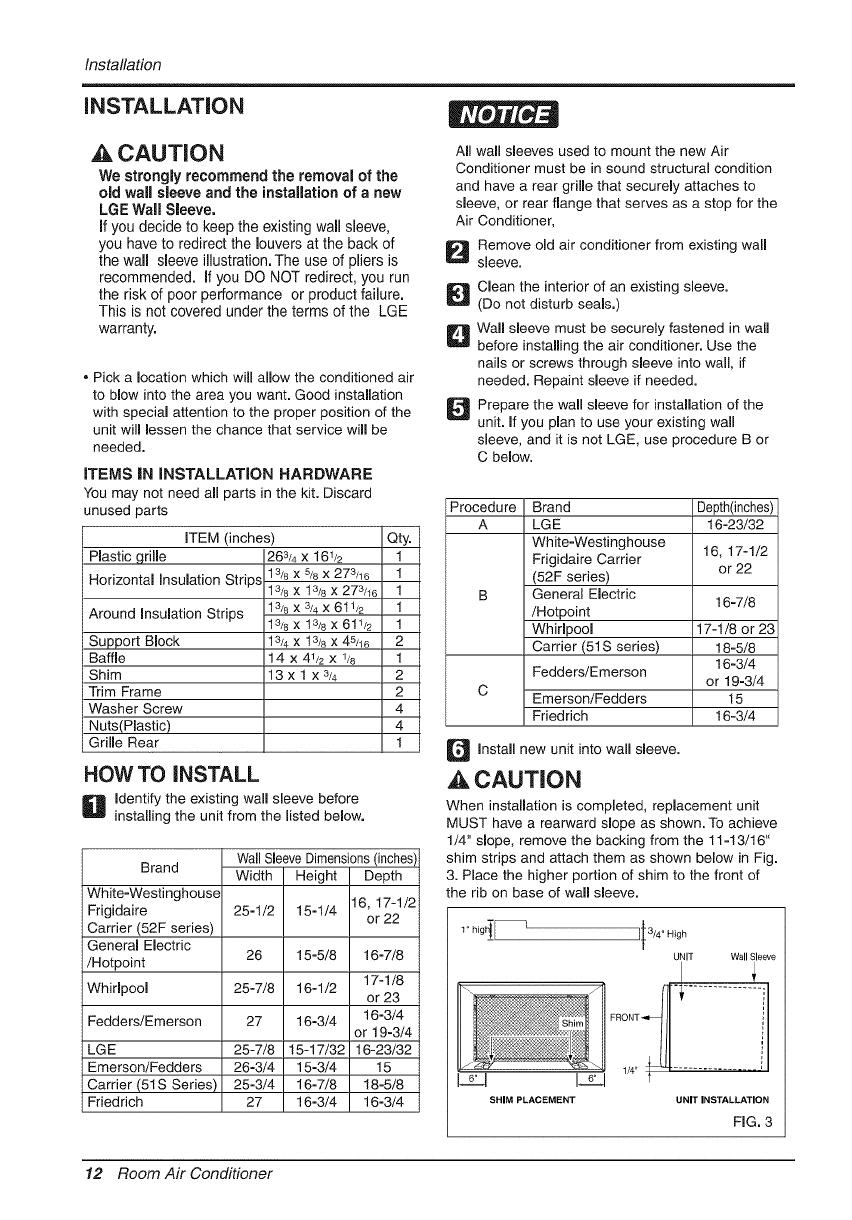
When installation is completed, replacement unit
MUST have a rearward slope as shown. To achieve
1/4" slope, remove the backing from the 11-13/16"
shim strips and attach them as shown below in Fig.
3. Place the higher portion of shim to the front of
the rib on base of wall sleeve.
UNIT WallSleeve
SHIM PLACEMENT UNIT INSTALLATION
FIG. 3
12 Room Air Conditioner
Installation
PROCEDURE A
D f you are using the new sleeve (optionally
supplied with your unit),skip to step 3.
Otherwise, install the plastic grille from the kit.
Cut the plastic grille to 25-1/2" wide and 15-
1/4" high. Place the plastic grille to the inside
of the wall sleeve at the rear flange.
li Install the new unit into the wall sleeve.
]To assemble trim, snap the tab of each piece
into the slot of the other piece as shown below.
Slide trim over the front of the air conditioner
until trim is flush with sleeve as shown below.
FIG. 4
] Fasten the 4 washer screws to secure the
grille to the wall sleeve. If you need plastic nuts
to mount plastic grille to the inside of the wall
sleeve, there are plastic nuts in the installation
kit. The nuts are installed from the inside of the
sleeve and are pressed into the square holes
of the rear flanges.
or
-- FIG. 5
Remove the backing from the Horizontal
Insulation strip 13/8x 3/8x 273/16 and attach that
to the inside bottom of the sleeve as shown
below. Remove the backing from the Around
Insulation strip 13_8x 3/4x 611/2 and attach that
to the inside front of the sleeve as shown
below.
FIG. 6
Trim (2 ea)
Wall
i
FIG. 7
,A CAUTION
Air conditioners covered in this manual pose
an excessive weight hazard. Two or more
people are needed to move and install the
unit.
To prevent injury or strain, use proper lifting
and carrying techniques when moving unit.
When handling the air conditioner, be careful
to avoid cuts from sharp metal fins on front
and rear coils.
Make sure air conditioner does not fall during
removal.
Owner's Manual 13
Installation
PROCEDURE B
D edirect the louvers at the back of the wall
sleeve to 60° angle as shown in the FIG 8. The
use of pliers is recommended.
7 5/46"
(Top View)
FIG.8
_]_ emove the backing from the Horizontal
Insulation strip 13/8 X 5/8X 273/16 and attach that
to the inside bottom of the sleeve as shown
below. Remove the backing from the Around
Insulation strip 13/8 x 3/4x 611/2 and attach that
to the inside front of the sleeve as shown
below.
If the wall sleeve already has a rear grille, skip
to step 4. If the wall sleeve does not have a
rear grille or Iouvered panel, install the plastic
grille from the kit. Cut the plastic grille to 25-
1/2" wide and 15=1/4" high. Place the plastic
grille to the inside of the wall sleeve at the rear
flange.
Place the plastic grille
FIG. 9
FIG. 11
lf the depth of your existing wall sleeve is less
than or equal to 18", skip to step 6. Otherwise,
cut the baffles and the support blocks
according to length "A" in the table below.
Depth"D" of the existing Length "A"
wall sleeve (inches) (inches)
I8 <D_<18-% 314
18-% <D_<19-_/4 1=3/4
19-3/4<D_<22 4
A/i
_ Support
Block
_-- Baffle
FIG. 12
Fasten the 4 washer screws to secure the
grille to the wall sleeve. If you need plastic nuts
to mount plastic grille to the inside of the wall
sleeve, there are plastic nuts in the installation
kit. The nuts are installed from the inside of the
sleeve and are pressed into the square holes
of the rear flanges.
or
Fasten the screws
14 Room Air Conditioner
Installation
PROCEDURE B
] Remove the backing from the support blocks
and attach them to the inside of the wall sleeve
as shown FIG 13. Slide the baffle into slots of
the support blocks.
!ii!iiii:_:_........ (7_,,0,,)
ii,_i_iiiiii!i$iiii;:iiiiiilDi
_ Support
!iiiiiiii!ii%iiii_iii]iii!i!i!:!iiiiiiii':'_' Block
FIG. 13
,& CAUTION
Air conditioners covered in this manual pose
an excessive weight hazard. Two or more
people are needed to move and install the
unit.
To prevent injury or strain, use proper lifting
and carrying techniques when moving unit.
When handling the air conditioner, be careful
to avoid cuts from sharp metal fins on front
and rear coils.
Make sure air conditioner does not fall during
removal.
U Install the new unit into the wall sleeve.
]To assemble trim, snap the tab of each piece
into the slot of the other piece as shown below.
Slide trim over the front of the air conditioner
until trim is flush with sleeve as shown below.
Trim (2 ea)
Wall
FIG. 14
Owner's Manual 15
Installation
PROCEDURE C
D edirect the louvers at the back of the wall
sleeve to 60° angle as shown in the FIG 15.
The use of pliers is recommended.
7 13/1C
60_ ................... I__ 60°
RearLouvers
(Top V ew)
FIG. 15
D f the wall sleeve already has a rear grille, skip
to step 4. If the wall sleeve does not have a
rear grille or Iouvered panel, install the plastic
grille from the kit. Cut the plastic grille to 26-
1/2" wide and 15-1/2" high. Place the plastic
grille to the inside of the wall sleeve at the rear
flange.
Place the plastic grille FIG. 16
Fasten the 4 washer screws to secure the
grille to the wall sleeve. If you need plastic nuts
to mount plastic grille to the inside of the wall
sleeve, there are plastic nuts in the installation
kit. The nuts are installed from the inside of the
sleeve and are pressed into the square holes
of the rear flanges.
or
Fasten the screws FIG. 17
D emove the backing from the Horizontal
Insulation strip 13/8 x 13/8 x 273/16 and attach
that to the inside bottom of the sleeve as
shown below. Remove the backing from the
Around Insulation strip 13/8 x 13/8 x 611/2 and
attach that to the inside front of the sleeve as
shown below.
FIG. 18
_lf the of sleeve is less than
depth your existing
or equal to 18", skip to step 7. Otherwise, cut
the baffles and the support blocks according to
Length "A" in the table below.
Depth"D" of the existing Length "A" ,_
- Support
wall sleeve (inches) (inches) _-/_ Block
18 <D_<18-5/8 3/4
18-% <D_<19-3/4 1 =3/4 T_I - Baffle
19-3/4<D_<22 4 _ FIG. 19
Q emove the backing from the support blocks
and attach them to the inside of the wall sleeve
as shown FIG 20. Slide the baffle into slots of
the support blocks
Support
Block
FiG. 20
16 Room Air Conditioner
Installation
PROCEDURE C
@
Remove the backing from the 13" shim strips
and attach them as shown below in Fig. 22.
The higher portion of shim is to be placed in
front of the rib on the base of wall sleeve.
1" high__ I-
II 3/4" High
FIG. 21
161
Install the new unit into the wall sleeve
FIG. 22
D o assemble trim, snap the tab of each piece
into the slot of the other piece as shown below.
Slide trim over the front of the air conditioner
until trim is flush with sleeve as shown below.
Trim (2 ea)
Wall
FIG. 23
A CAUTION
Air conditioners covered in this manual pose
an excessive weight hazard. Two or more
people are needed to move and install the
unit.
To prevent injury or strain, use proper lifting
and carrying techniques when moving unit.
When handling the air conditioner, be careful
to avoid cuts from sharp metal fins on front
and rear coils.
Make sure air conditioner does not fall during
removal.
Owner's Manual 17
OperatingInstructions
The controls will look like one of the foflowing.
-FAN SPEED
Everytime you push this button,it advancesthe setting as follows: {High[F2] _ Low[F1]_ High[F2]}
(-TIMER
- SHUT-OFF TIME
You will usually use shut-offtime whileyou sleep.
• If unit is running, use Timer to set number of hours until shut-off.
• Foryour sleeping comfort, once Time isset, the Temperature
setting will raise 2°F after 30 min., and once again after another
30 rain.
• Push Timer button to advance setting from 1Hour * 2Hours _...
• 12Hours maximum.
- START TIME
• If unit is off, use Timer to set number ofhours before unit starts.
• Push Timer button to advance setting from 1Hour * 2Hours _...
12Hours maximum.
MODE
REMOTECONTROLSIGNAL
RECEIVER
TEMPERATURE SETTING
• Use this button to automatically control the
temperature of the room.
The temperature can be set within a range of
60°F to 86°Fby increments of I°F.
• The setting appears in the display.
POWER
• Toturn the air conditioner ON, pushthis button.
To turn the air conditioner OFF, push the button
again.
• This button takes priority over any other button.
- Push this button to shift mode of operation from COOL _ENERGY SAVER * FAN * HEAT
- COOL:
Fan runs continually for normal cooling operation.
- ENERGY SAVER:
The fan stops when the compressor stops cooling. Approximately every 3 minutes the fan will turn onand the unit will
check the room air temperature to determine ifcooling is needed.
- FAN:
Fan-only operation.
- HEAT:
Fan runs continually for normal heating operation.
_d after an electrical power failure, the unit will begin to run at its last setting. J
18 Room Air Conditioner
Operating Instructions
The remote control and control panel will leek like one of the following pictures.
POWER
To turn the air conditioner ON, push this button.
To turn the air conditioner OFF, push the button again.
This button takes priority over any other button.
TEMPERATURE SETTING
Use this button to automatically control the temperature of the room.
The temperature can be set within a range of 60"F to 86°F by
increments of I°F.
The setting appears in the display.
FAN SPEED
Every time you push this button it advances the setting as follows:
{High[ F2] _Low[ F1 ] _High[ F2]}
TIMER
- SHUT-OFF TIME
• You will usually use shut-off time while you sleep.
• If unit is running, use Timer to set number of hours until shut-off.
• For your sleeping comfort, once Time is set, the Temperature setting will
raise 2°F after 30 rain, and once again after another 30 rain.
• Push Timer button to advance setting from 1Hour * 2Hours * ... *
12Hours maximum.
- START TIME
If unit is off, use Timer to set of hours before unit starts.
Push Timer button to advance setting from 1Hour * 2Hours * ... *
12Hours maximum.
Fan Speed
MODE
- Push this button to shift mode of operation from COOL _ENERGY SAVER _FAN * Heat.
- COOL:
Fan runs continually for normal cooling operation.
- ENERGY SAVER:
• The fan stops when the compressor stops cooling. Approximately every 3 minutes the fan will turn on
and the unit will check the room air temperature to determine if cooling is needed.
- FAN:
Fan-only operation.
- HEAT:
Fan runs continually for normal heating operation.
,& CAUTION
When the air conditioner has been performed its
cooling or heating operation and is turned off or
set to the fan position, wait at least 3 minutes
before resetting to the cooling operation again.
A slight heat odor may come from the unit
when first switching to HEAT after the
cooling season is over. This odor, caused
by fine dust particles on the heater, will
disappear quickly. This is harmless.
Owner's Manual 19
OperatingInstructions
1. Remove the cover from the back of the remote
controller.
2. Insert two batteries.
Be sure that the (+) and (-) directions are
correct.
Be sure that both batteries are new.
3. Re-attach the cover.
Push the lever to the "CLOSE" position to cool, heat or
recirculate room air only.
Pullthe leverto the "OPEN" positionto exhaust smokeor
stale air from the room.
This feature is best used in conjunction with the FANONLY
position.
Do not use rechargeable batteries.
Such batteries differ from standard
dry cells in shape, dimensions, and
performance.
Remove the batteries from the
remote controller if the air
conditioner is not going to be used
for an extended length of time.
PULL OPEN / PUSH CLOSE
The direction of air can be controlled by adjusting the horizontal
andvertical louvers.
HORIZONTAL AIR-DIRECTION CONTROL
The horizontal air direction is adjusted bymoving the vertical
louver.
The leverfor the vertical louver is located in the right andleft side
of the air discharge.
,'VERTICAL AIR-DIRECTION CONTROL
The vertical air direction is adjusted bymoving the horizontal
louver.
_MM
20 Room Air Conditioner
  • Page 1 1
  • Page 2 2
  • Page 3 3
  • Page 4 4
  • Page 5 5
  • Page 6 6
  • Page 7 7
  • Page 8 8
  • Page 9 9
  • Page 10 10
  • Page 11 11
  • Page 12 12
  • Page 13 13
  • Page 14 14
  • Page 15 15
  • Page 16 16
  • Page 17 17
  • Page 18 18
  • Page 19 19
  • Page 20 20
  • Page 21 21
  • Page 22 22
  • Page 23 23
  • Page 24 24
  • Page 25 25
  • Page 26 26
  • Page 27 27
  • Page 28 28
  • Page 29 29
  • Page 30 30
  • Page 31 31
  • Page 32 32
  • Page 33 33
  • Page 34 34
  • Page 35 35
  • Page 36 36
  • Page 37 37
  • Page 38 38
  • Page 39 39
  • Page 40 40
  • Page 41 41
  • Page 42 42
  • Page 43 43
  • Page 44 44
  • Page 45 45
  • Page 46 46
  • Page 47 47
  • Page 48 48

LG LT1030HR Owner's manual

Type
Owner's manual
This manual is also suitable for

Ask a question and I''ll find the answer in the document

Finding information in a document is now easier with AI

in other languages