Broadcast Tools GPI-16 Plus/RJ Owner's manual
- Type
- Owner's manual
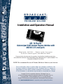
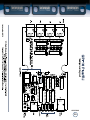
Broadcast Tools GPI-16 Plus/RJ is a 16-input general-purpose interface that provides easy interfacing between external devices and a PC's USB or RS-232 port. It features four RJ45 jacks for simplified wiring, user-selectable unit ID and baud rate, and LED indicators for all inputs and power. Ideal for use with the Broadcast Tools COA-37 XDS/RJ adapter to control satellite receivers or for any application requiring general-purpose logic inputs.
Broadcast Tools GPI-16 Plus/RJ is a 16-input general-purpose interface that provides easy interfacing between external devices and a PC's USB or RS-232 port. It features four RJ45 jacks for simplified wiring, user-selectable unit ID and baud rate, and LED indicators for all inputs and power. Ideal for use with the Broadcast Tools COA-37 XDS/RJ adapter to control satellite receivers or for any application requiring general-purpose logic inputs.


-
 1
1
-
 2
2
-
 3
3
-
 4
4
-
 5
5
-
 6
6
-
 7
7
-
 8
8
-
 9
9
-
 10
10
-
 11
11
-
 12
12
-
 13
13
-
 14
14
-
 15
15
-
 16
16


Broadcast Tools GPI-16 Plus/RJ Owner's manual
- Type
- Owner's manual
Broadcast Tools GPI-16 Plus/RJ is a 16-input general-purpose interface that provides easy interfacing between external devices and a PC's USB or RS-232 port. It features four RJ45 jacks for simplified wiring, user-selectable unit ID and baud rate, and LED indicators for all inputs and power. Ideal for use with the Broadcast Tools COA-37 XDS/RJ adapter to control satellite receivers or for any application requiring general-purpose logic inputs.
Ask a question and I''ll find the answer in the document
Finding information in a document is now easier with AI
Related papers
-
Broadcast Tools GPI-16 Owner's manual
-
Broadcast Tools GPI-16 Plus Owner's manual
-
-
-
-
-
-
-
-