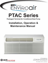
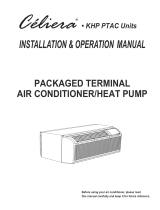
Cooper&Hunter CH-PT12HPGF User manual

Category
Split-system air conditioners
Type
User manual
PACKAGED TERMINAL
AIR CONDITIONER
WITH HEAT PUMP
SERVICE MANUAL
Model: CH-PT09HPGF
Designed by Cooper&Hunter International Corporation, Oregon, USA
www.cooperandhunter.com
F or proper operation, please read and keep this manual carefully.
CONTENTS
1. Precaution
1.1 Safety Precaution
1.2 Warning
2. Functions and control panel.
3. Dimension
4. Refrigerant Cycle Diagram
5. Electronic function
5.1 Terms and definitions
5.2 Electric Control working environment
5.3 Protection function
5.4 Operation of fan motor
5.5 Operation of compressor
5.6 Dip switches and Jumper selection
5.7 Functions for Front desk switch panel and Wire Controller
6. Unit components
7. Installation details
7.1 How to install the unit
7.2 Care and cleaning
8 Operation characteristics
8.1 Cooling operation
8.2 Heating operation
9 Power connection options
10 Troubleshooting
P1-4
P1
P1-4
P5-7
P8
P9
P10-16
P10
P10
P10
P10-12
P12
P13-14
P15
P16
P17-20
P17-19
P19-20
P21
P21
P21
P21
P22-23
P24-29
1. Precaution
1.1 Safety Precaution.
● To prevent injury to the user or other people and property damage, the following instructions must be
followed.
Incorrect operation due to ignoring instruction will cause harm or damage.
Before service unit, be sure to read this service manual at first.
1.2 Warning
INSTALLATION
● Do not use a defective or underrated circuit breaker. Use this appliance on a dedicated circuit.
There is risk of fire or electric shock.
● For electrical work, contact the dealer, seller, a qualified electrician, or an Authorized service center.
Do not disassemble or repair the product, there is risk of fire or electric shock.
● Always ground the product.
There is risk of fire or electric shock.
● Install the panel and the cover of control box securely.
There is risk of fire of electric shock.
● Always install a dedicated circuit and breaker.
Improper wiring or installation may cause fore or electric shock.
● Use the correctly rated breaker of fuse.
There is risk of fire or electric shock.
● Do not modify or extend the power cab
There is risk of fire or electric shock.
● Do not install, remove, or reinstall the unit by yourself(customer).
There is risk of fire, electric shock, explosion, or injury.
● Be caution when unpacking and installing the product.
Sharp edges could cause injury, be especially careful of the case edges and the fins on the condenser and
evaporator.
● For installation, always contact the dealer or an Authorized service center.
There is risk of fire, electric shock, explosion, or injury.
1
● Do not install the product on a defective installation stand.
It may cause injury, accident, or damage to the product.
● Be sure the installation area does not deteriorate with age.
If the base collapses, the air conditioner could fall with it, causing property damage, product failure, and personal
injury.
● Do not let the air conditioner run for a long time when the humidity is very high and a door
or a window is left open.
Moisture may condense and wet or damage furniture.
● Take care to ensure that power cable could not be pulled out or damaged during operation.
There is risk of fire or electric shock.
● Do not place anything on the power cable.
There is risk of fire or electric shock.
● Do not plug or unplug the power supply plug during operation.
There is risk of fire or electric shock.
● Do not touch (operation) the product with wet hands.
There is risk of fire or electric shock.
● Do not place a heater or other appliance near the power cable.
There is risk of fire and electric shock.
● Do not allow water to run into electric parts.
It may cause fire, failure of the product, or electric shock.
● Do not store or use flammable gas or combustible near the product.
There is risk of fire or failure of product.
● Do not use the product in a tightlyclosed space for a long time.
Oxygen deficiency could occur.
● When flammable gas leaks, turn off the gas and open a window for ventilation before turn
the product on.
Do not use the telephone or turn switches on or off. There is risk of explosion or fire.
● If strange sounds, or small or smoke comes from product. Turn the breaker off or
disconnect the power supply cable.
There is risk of electric shock or fire.
● Stop operation and close the window in storm or hurricane. If possible, remove the product
from the window before the hurricane arrives.
There is risk of property damage, failure of product, or electric shock.
2
● Do not open the inlet grill of the product during operation.
(Do not touch the electrostatic filter, if the unit is so equipped.)
There is risk of physical injury, electric shock, or product failure.
● When the product is soaked (flooded or submerged), contact an Authorized service center.
There is risk of fire or electric shock.
● Be caution that water could not enter the product.
There is risk of fire, electric shock, or product damage.
● Ventilate the product from time to time when operating it together with a stove, etc.
There is risk of fire or electric shock.
● Turn the main power off when cleaning or maintaining the product.
There is risk of electric shock.
● When the product is not be used for a long time, disconnect the power supply plug or turn
off the breaker.
There is risk of product damage or failure, or unintended operation.
● Take care to ensure that nobody could step on or fall onto the outdoor unit.
This could result in personal injury and product damage.
CAUTION
● Always check for gas (refrigerant) leakage after installation or repair of product.
Low refrigerant levels may cause failure of product.
● Install the drain hose to ensure that water is drained away properly.
A bad connection may cause water leakage.
● Keep level even when installing the product.
To avoid vibration of water leakage.
● Do not install the product where thenoise or hot air from the outdoor unit could damage
the neighborhoods.
It may cause a problem for your neighbors.
● Use two or more people to lift and transport the product.
Avoid personal injury.
● Do not install the product where it will be exposed to sea wind (salt spray) directly.
It may cause corrosion on the product. Corrosion, particularly on the condenser and evaporator fins, could cause
product malfunction or inefficient operation.
3
OPERATIONAL
● Do not expose the skin directly to cool air for long periods of time.
(Do not sit in the draft).
This could harm to your health.
● Do not use the product for special purposes, such as preserving foods, works of art, etc. It
is a consumer air conditioner, not a precision refrigerant system
There is risk of damage or loss of property.
● Do not block the inlet or outlet of air flow.
It may cause product failure.
● Use a soft cloth to clean. Do not use harsh detergents, solvents, etc.
There is risk of fire, electric shock, or damage to the plastic parts of the product.
● Do not touch the metal parts of the product when removing the air filter. They are very
sharp.
There is risk of personal injury.
● Always insert the filter securely. Clean the filter every two weeks or more often if
necessary.
A dirty filter reduces the efficiency of the air conditioner and could cause product malfunction or damage.
● Do not insert hands or other object through air inlet or outlet while the product is operated.
There are sharp and moving parts that could cause personal injury.
● Do not drink the water drained from the product.
It is not sanitary could cause serious healthissues.
● Use a firm stool or ladder when cleaning or maintaining the product.
Be careful and avoid personal injury.
● Replace the all batteries in the remote control with new ones of the same type. Do not mix
old and new batteries or different types of batteries.
There is risk of fire or explosion.
● Do not recharge or disassemble the batteries. Do not dispose of batteries in a fire.
They may burn of explode.
● If the liquid from the batteries gets onto your skin or clothes, wash it well with clean water.
Do not use the remote of the batteries have leaked.
The chemical in batteries could cause burns or other health hazards.
4
2. Functions and control panel.
The controls featured in this manual are representative of many available models. Your model
may offer slightly different features.
·
POWER
- Press the POWER button to turn the unit on or off.
When the unit is on,the power indicator light will be green.When the unit is off,the light will go out.
·
MODE
- Push this button to cycle through the modes from COOL-HEAT-FAN-COOL.The green indicator light beside the "MODE"
option will illuminate, identifying the mode selected.
- COOL:The range of set temperature is 17
/62
~30
/86
.Cooling begins automatically when the room temperature is
above the set point,and stops when the room temperature is 2
(4
) below the set point.But the compressor will run 5
minutes at least in COOL mode before stoping. The fan runs in continuous mode.
- HEAT:The range of set temperature is 17
/62
~29
/84
.For heat pump models,the unit can alternate to run between in
reverse cycle heat mode and electric heater mode according to the difference between the setting temperature and the room
temperature.The fan motor cycles on and off with the compressor and electric heater.
NOTE: The reverse cycle and electric heater can not be run at the same time.
In following cases, it is normal that the reverse
cycle does not operate.
1.When the outdoor temperatrue is lower than 4
/40
or the room temperature falls to 4.5
/8
below the set point
temperature.
2.There is a 3-minute minimum compressor run time at any setting to prevent short cycling. The indoor fan motors starts before
the compressor and stops after the compressor cycles off.
3.When frost builds up to the evaporator coils, the unit will defrost automatically and the compressor will cycle off.
- FAN:Fan operation only without heating and cooling.
5
UP/DOWN BUTTONS ( ▲ / ▼ )
- Push the UP (or DOWN) button to increase (or decrease) the set temperature of the unit in cooling
or heating mode.The temperature can be set by increments of 1
(1
).The setting temperature
appears in the display.
NOTE:Press and hold ▲ and ▼ buttons together for 3 seconds will alternate the temperature display between
&
scale.
FAN (FAN SPEED)
- Every time you push this button, the fan speed cycles through the settings as follows: HIGH-MED- LOW-HIGH.
DISPLAYS:
- Shows the set temperature in
or
. While on Fan only mode, it shows the room temperature.
Control code:
LC-Pads on the control panel is not available. The unit can be set by using wire controller only.
Note:
When receiving the wired remote control signal display LC. Or when wired remote control signal is not
received within the panel key operation for 5 seconds to display LC
FC-
Front desk control
6
Turn the switch to of f
You can connect the front desk
switch for two ways.
Error codes:
AS- Open or short circuit of room temperature sensor (T1);
ES- Open or short circuit of evaporator temperature sensor( T2 );
CS-Open or short circuit of condenser temperature sensor (T3);
oS-Open or short circuit of outside temperature sensor(T4);
HS- Open or short circuit of exhaust temperature sensor( T5 or T6);
Other codes:
LO-Room temperature is lower than 0
/32
;
HI-Room temperature is higher than 37
/99
E4- Communication malfunction between main control board and display board
LE- Drive-by-wire controller failure
7
3. Dimension
Top View
D
W
H
Front View
Dimension :
Dimension 1
no sleeve,rear grille,and rear net)
Dimension 2
no rear grille and rear net, but include sleeve)
Dimension 3
include sleeve and rear net)
Dimension 4
include sleeve, rear net and rear grille)
WxHxDmm)
WxHxDinch)
1067x406x532
42.0x15.9x20.9
1067x408x578
42.0x16.0x22.8
1067x408x588
42.0x16.0x23.1
1067x408x606
42.0x16.0x23.9
8
4. Refrigerant Cycle Diagram
The figure below is a brief description of the important components and their function in what is called the
refrigeration system.
This will help to understand the refrigeration cycle and the flow of the refrigerant in the Heat Pump Cycle.
LIQUID SIDE
HEAT
EXCHANGE
(EVAPORATOR)
CHECK VALVE
(Heating Model only)
CAPILIARY TUBE
HEAT
EXCHANGE
(CONDENSER)
GAS SIDE
ACCUMULATOR
COMPRESSOR
REVERSING VALVE
(Heating Model only)
COOLING
HEATING
9
5. Electronic function
5.1 Terms and definitions
T1: Temperature of indoor ambient
T2: Temperature of evaporator
T3: Temperature of condenser
T4: Temperature of outdoor ambient
TS: The set temperature.
DAHT: Temperature of discharge (T5)
DAHT: Temperature of discharge (T6)
5.2 Electric Control working environment
Input voltage: 265V, 60Hz; 230/208V, 60Hz
5.3 Protection function
5.3.1 The compressor functions protection with a delay of three minutes.
5.3.2 Sensor protection at open or short circuit.
5.3.3 Evaporator anti-freezing protection at cooling mode.
5.4 Operation of fan motor
5.4.1. Fan motor is on when compressor is on, Fan motor is off when compressor is off. (except theT2 high
Temp. protection).
If there’s only one speed of the fan motor, use the high speed instead of the low speed.
5.4.2. The fan motor operates at the cooling only mode (see FIG.A)
T4 Operate on high speed
T01
T02
Operate on low speed
FIG.A
10
When T4
T01 and lasts for 1 minute, the fan motor will operates at high speed.
When T4
T02 and lasts for 1 minute, the fan motor will operates at low speed.
When T02≤T4≤T01:
A) If fan motor is off originally, it will operate at high speed.
B) If fan motor is on originally, it will keep on working at the original speed.
5.4.3. The fan motor operates at the heat pump and cooling mode( see FIG.B)
T4 Operate on low speed
T03
T04
Operate on high speed
FIG.B
When T4≥T03 and lasts for 1 minute, the fan motor will operates at low speed.
When T4≤T04 and lasts for 1 minute, the fan motor will operates at high speed.
When T04 T4 T03:
A) If fan motor is off originally, it will operate at high speed.
B) If fan motor is on originally, it will keep on working at the original speed.
5.4.4. The high temperature protection of evaporator at the heat pump and cooling mode as
below:
11
If T2 TE7, this unit turns into the protection of compressor off , and quits this protection when T2≤TE9.
If T2 TE8,it turns into the protection of fan motor off , and quits this protection when T2≤TE9.
If T2 TE15, fan motor operates at low speed by force, then quits the operation and determines the
high or low speed by T4.
5.4.5. At the fan only mode, the fan always keeps on working, and the compressor/fan
motor/heater stop working.
5.5 Operation of compressor
5.5.1. The compressor operates at cooling mode as below:
Operation condition
(T1-Ts)
+0
-4
T1≥Ts
Compressor on
Compressor off
compressor on
T1≤Ts-4
. compressor off
5.5.2. The compressor operates at heating mode:
(There are two ways of heating mode: Heat pump and cooling/Electric heater and cooling)
The electrical heater or compressor will be activated by sensing the difference between setting
temperature and the actual ambient room temperature.
Operation condition for
heater or compressor
(T1-Ts)
Heater(compressor) off
2
-2
Heater(compressor) on
12
5.5.2.1 The Electric heater operates as below:
a.When T1 Ts-2, the fan motor operates, and 3 seconds later, the heater is on and operates at low speed
within 30 seconds. After 30 seconds, it will change to the setting speed. If the DAHT temperature checked is
higher than the protection temperature, when the heater operating, the fan motor will be off automatically.
b. When T1≥Ts+2
, the heater is off, and the fan motor keeps on working at setting speed. If the DAHT temperature
checked is low than the protection temperature, and the operation time of fan motor is more than 15 seconds, then
the fan motor will be off. If the T2 protection gets started, the fan motor also does not work.
5.5.2.2 The Heat pump operates as below:
The Heat pump′s operation mode is in accordance with the way of compressor′s working. The compressor is on (electric heater
is off), the fan motor operates according to the anti-cold wind of heat pump. The four-way valve always keeps on. When T1<Ts-2
, the compressor is on, and when T1≥Ts+2
,it will be off. The fan motor works according to the operation of compressor. If
T2>TE7, the compressor is off by force. When the DAHT protection gets started, it is not allowed that the compressor operates.
5.6 Dip switches and Jumper selection
Note: This Switch board is optional.
13
Dip Switches configurations and functions of each dip switch
position.
(See Figure and Table 1 as below)
Table 1 DIP SWITCHES CONFIGURATIONS
No.
UP(ON)
DOWN(OFF)
Remarks
S1
Electric Heat Only
Electric Heat and Pump Heat
For Heat Pump unit only
S2
Temperature Display in
S3
Wall Thermostat Enable
Control Panel Enable
S4*S5
UP*UP:61~86(16~30);
UP*DOWN:65~78(18 ~26);
DOWN*UP:63~80(17 ~27);
DOWN*DOWN:68~75(20 ~24);
Two configurations (S4*S5)
combine to select set point
range.
S6
Fan Continuous Run for Heating
Fan Cycle for Heating
S7
Fan Continuous Run for Cooling
Fan Cycle for Cooling
S8
Low temp. Protection enable
Low temp. Protection disable
S9
Use some types of wall
Thermostat
Use PTAC other Wall
Thermostat
You can consult with the
sales agency or manufacturer
for details
NOTE: On heating mode, the setting temperature can’t be higher than 29
/84
.
* Electric Heat Only (for heat pump unit only)
- This setting is typically used for Emergency Heating.
* Wall Thermostat Enable
- A wired wall thermostat can be connected to the unit .If it is, this dip switch must be moved to the
Wall Thermostat Enable Position, before the wall thermostat will begin control.
* Set-point Temperature Limits
- Provides a restricted range of temperature control.
.Heat and Cool Fan CON/CYC Dip-switches
- Allows the fan to operate in continuous or cycle modes while the unit is in heating and cooling mode.
* Continuous (CON)
- Allows fan to run continuously, circulating air even when the temperature setting has been satisfied. This
switch helps to maintain the room temperature closer to the thermostat setting.
* Cycle (CYC)
- This setting allows the fan to cycle on and off with the compressor or electric heater. The fan stops a short
time after the temperature setting is satisfied.
14
5.7 Functions for Front desk switch panel and Wire Controller.
1.Front desk switch panel: if a ON/OFF switch is connected to the ports, you can turn off A/C unit with it.
Then the digital LED on the unit will display FC.
(The FIG.A shows you how to connect the units)
2. Wired controller: the digital LED will display LC (Reserved) if a wired controller is connected.
if the communication portal is one way, the buttons on the control panel will be invalid.
Note: This wired controller is optional, and it’s matched with the switch board.
FRONT DESK SWITCH PANEL
ROOM 100 ROOM 101 ROOM N
FIELD-SUPPLIED
24V
TRANSFORMER
(SEE NOTE1)
Black
White
Black
White
Black
White
PTAC #1 PTAC #2 PTAC #N
15
SUGGESTIONS:
1. TO Size transformer, use the following equation:
Quantity of PTAC units x 1va=Transformer Size (va)
Example: 110 PTAC units x1va=110va Transformer
2. Following are American Wire Gauge recommended sizes:
AWG WIRE SIZE NO.
24
22
20
18
16
MAX. LENGTH (ft)
400
600
900
1500
2000
6. Unit components
Decomposition figure
16
wall
Installation figure
7. Installation details
7.1 How to install the unit
iINSTALLATION
!
CAUTION
There are sharp edges that can cause serious cuts.
When lifting the air conditioner, it is HEAVY. Use 2 people to lift.
17
- For existing sleeve, you should measure the wall
sleeve dimensions.
- Install the new air conditioner according to these
installation instructions to achieve the best performance.
All wall sleeves used to mount the new air conditioner
must be in good structural condition and have a rear
grille that securely attaches to the sleeve or the flange
of the sleeve to secure the new air conditioner.
- To avoid vibration and noise, make sure the unit is
installed securely and firmly.
- When installing the sleeve, make certain there is
Dimension of air conditioner
nothing within 20 of the back that would interfere
with heat radiation and exhaust air flow. (See Fig.2)
PREPARATION OF SLEEVE ASSEMBLY(optional)
- Refer to the installation instruction of sleeve assembly
for details.
UNIT INSTALLATION
- Carefully remove shipping tapes from the front panel.
(See Fig.3)
- Remove the front panel. (See Fig.4)
- Remove the shipping screw from the vent door.
(See Fig.5)
UNIT INSTALLATION (CONTINUED)
- Rotate the vent control lever to either open or close the vent
door. (See Fig.6)
w
18
  • Page 1 1
  • Page 2 2
  • Page 3 3
  • Page 4 4
  • Page 5 5
  • Page 6 6
  • Page 7 7
  • Page 8 8
  • Page 9 9
  • Page 10 10
  • Page 11 11
  • Page 12 12
  • Page 13 13
  • Page 14 14
  • Page 15 15
  • Page 16 16
  • Page 17 17
  • Page 18 18
  • Page 19 19
  • Page 20 20
  • Page 21 21
  • Page 22 22
  • Page 23 23
  • Page 24 24
  • Page 25 25
  • Page 26 26
  • Page 27 27
  • Page 28 28
  • Page 29 29
  • Page 30 30
  • Page 31 31

Cooper&Hunter CH-PT12HPGF User manual

Category
Split-system air conditioners
Type
User manual

Ask a question and I''ll find the answer in the document

Finding information in a document is now easier with AI