Page is loading ...

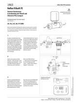
Fillcontrol Auto 06.07.2016 - Rev. B
GB
Operating manual
Original operating manual


Contents
Fillcontrol Auto — 06.07.2016 - Rev. B English —
3
English
Fillcontrol Auto
06.07.2016 - Rev. B
Contents
1 Notes on the operating manual..................................................................................................................................................... 5
2 Liability and guarantee................................................................................................................................................................... 5
3 Safety................................................................................................................................................................................................ 6
3.1 Explanation of symbols ........................................................................................................................................................................ 6
3.1.1 Symbols and notes used ................................................................................................................................................... 6
3.2 Personnel requirements ...................................................................................................................................................................... 7
3.3 Personal protective equipment .......................................................................................................................................................... 7
3.4 Intended use .......................................................................................................................................................................................... 7
3.5 Inadmissible operating conditions..................................................................................................................................................... 7
3.6 Residual risks ......................................................................................................................................................................................... 8
4 Description of the device................................................................................................................................................................ 9
4.1 Description ............................................................................................................................................................................................. 9
4.2 Overview .............................................................................................................................................................................................. 10
4.3 Identification ....................................................................................................................................................................................... 11
4.3.1 Nameplate ........................................................................................................................................................................ 11
4.3.2 Type code .......................................................................................................................................................................... 11
4.4 Function ............................................................................................................................................................................................... 12
4.5 Scope of delivery ................................................................................................................................................................................. 13
4.6 Optional equipment and accessories .............................................................................................................................................. 13
5 Technical data ............................................................................................................................................................................... 14
5.1 Electrical system .................................................................................................................................................................................. 14
5.2 Dimensions and connections ............................................................................................................................................................ 14
5.3 Operation ............................................................................................................................................................................................. 14
6 Installation ..................................................................................................................................................................................... 15
6.1 Installation conditions ....................................................................................................................................................................... 16
6.1.1 Incoming inspection ....................................................................................................................................................... 16
6.2 Preparatory work ................................................................................................................................................................................ 16
6.3 Execution .............................................................................................................................................................................................. 17
6.3.1 Floor mounting ................................................................................................................................................................ 18
6.3.2 Hydraulic connection ...................................................................................................................................................... 19
6.4 Switching and make-up variants ...................................................................................................................................................... 20
6.5 Electrical connection .......................................................................................................................................................................... 22
6.5.1 Terminal diagram ............................................................................................................................................................ 23
6.5.2 RS-485 interface............................................................................................................................................................... 25
6.6 Installation and commissioning certificate ..................................................................................................................................... 25
7 Commissioning.............................................................................................................................................................................. 26
7.1 Requirements for initial commissioning ......................................................................................................................................... 26
7.2 Determining the P0 minimum operating pressure for the controller ......................................................................................... 26
7.3 Filling the device with water ............................................................................................................................................................. 27
7.4 Modifying the controller's start routine .......................................................................................................................................... 28
7.5 Parametrising the controller in the Customer menu .................................................................................................................... 29
7.6 Function test ........................................................................................................................................................................................ 29
7.7 Use the device to fill the facility system with water ...................................................................................................................... 30
7.8 Starting Automatic mode .................................................................................................................................................................. 30
8 Operation ....................................................................................................................................................................................... 31
8.1 Operating modes ................................................................................................................................................................................ 31
8.1.1 Automatic mode .............................................................................................................................................................. 31

Contents
4 — English Fillcontrol Auto — 06.07.2016 - Rev. B
8.1.2 Manual mode ................................................................................................................................................................... 31
8.1.3 Stop mode ........................................................................................................................................................................ 32
8.1.4 Summer operation .......................................................................................................................................................... 32
8.1.5 Restarting ......................................................................................................................................................................... 32
9 Controller ...................................................................................................................................................................................... 33
9.1 Operator panel .................................................................................................................................................................................... 33
9.2 Configuring settings in the controller ............................................................................................................................................. 34
9.2.1 Customer menu ............................................................................................................................................................... 38
9.2.2 Service menu .................................................................................................................................................................... 38
9.3 Messages .............................................................................................................................................................................................. 39
10 Maintenance ................................................................................................................................................................................. 42
10.1 Maintenance schedule ....................................................................................................................................................................... 43
10.2 Exterior leak test ................................................................................................................................................................................. 44
10.3 Cleaning the dirt trap ......................................................................................................................................................................... 44
10.4 Maintenance certificate ..................................................................................................................................................................... 45
11 Disassembly .................................................................................................................................................................................. 46
12 Annex ............................................................................................................................................................................................ 47
12.1 Reflex Customer Service .................................................................................................................................................................... 47
12.2 Guarantee ............................................................................................................................................................................................ 47
12.3 Conformity and standards ................................................................................................................................................................. 47

Notes on the operating manual
Fillcontrol Auto — 06.07.2016 - Rev. B English —
5
1 Notes on the operating manual
This operating manual is an important aid for ensuring the safe and reliable functioning of the device.
The operating manual will help you to:
• avoid any risks to personnel.
• become acquainted with the device.
• achieve optimal functioning.
• identify and rectify faults in good time.
• avoid any faults due to improper operation.
• cut down on repair costs and reduce the number of downtimes.
• improve the reliability and increase the service life of the device.
• avoid causing harm to the environment.
Reflex Winkelmann GmbH accepts no liability for any damage resulting from failure to observe the information in this operating manual.
In addition to the requirements set out in this operating manual, national statutory regulations and provisions in the country of
installation must also be complied with (concerning accident prevention, environment protection, safe and professional work practices,
etc.).
This operating manual describes the device with basic equipment and interfaces for optional equipment with additional functions. For
optional equipment and accessories, see chapter 4.6 "Optional equipment and accessories" on page 13 .
Note!
Every person installing this equipment or performing any other work at the equipment is required to carefully read this
manual prior to commencing work and to comply with its in
structions. The manual is to be provided to the device operator
and must be stored near the device for access at any time.
2 Liability and guarantee
The device has been built according to the state of the art and recognised safety rules. Nevertheless, its use can pose a risk to life and
limb of personnel or third persons as well as cause damage to the system or other property.
It is not permitted to make any modifications at the device, such as to the hydraulic system or the circuitry.
The manufacturer shall not be liable nor shall any warranty be honoured if the cause of any claim results from one or more of the
following causes:
• Improper use of the device.
• Unprofessional commissioning, operation, service, maintenance, repair or installation of the device.
• Failure to observe the safety information in this operating manual.
• Operation of the device with defective or improperly installed safety/protective equipment.
• Failure to perform maintenance and inspection work according to schedule.
• Use of unapproved spare parts or accessories.
Prerequisite for any warranty claims is the professional installation and commissioning of the device.
Note!
Arrange for Reflex Customer Service to carry out commissioning
and annual maintenance, see chapter 12.1 "Reflex
Customer Service
" on page 47 .

Safety
6
— English Fillcontrol Auto — 06.07.2016 - Rev. B
3 Safety
3.1 Explanation of symbols
3.1.1 Symbols and notes used
The following symbols and signal words are used in this operating manual.
DANGER
Danger of death and/or serious damage to health
• The sign, in combination with the signal word 'Danger', indicates imminent danger; failure to observe the safety information will
result in death or severe (irreversible) injuries.
WARNING
Serious damage to health
• The sign, in combination with the signal word 'Warning', indicates imminent danger; failure to observe the safety information can
result in death or severe (irreversible) injuries.
CAUTION
Damage to health
• The sign, in combination with the signal word 'Caution', indicates danger; failure to observe the safety information can result in
minor (reversible) injuries.
ATTENTION
Damage to property
• The sign, in combination with the signal word 'Attention', indicates a situation where damage to the product itself or objects within
its vicinity can occur.
Note!
This symbol, in combination with the signal word 'Note', indicates
useful tips and recommendations for efficient handling
of the product.

Safety
Fillcontrol Auto — 06.07.2016 - Rev. B English —
7
3.2 Personnel requirements
Only specialist personnel or specifically trained personnel may install and operate the equipment.
The electric connections and the wiring of the device must be executed by a specialist in accordance with all applicable national and
local regulations.
3.3 Personal protective equipment
When working at the system, wear the stipulated personal equipment such as hearing and eye protection, safety boots, helmet,
protective clothing, protective gloves.
See the national regulation of your country for personal protective equipment required.
3.4 Intended use
The device is a pressure maintaining station for heating and cooling water systems. It is intended to maintain the water pressure and to
add water within a facility system. The devices may be used only in systems that are sealed against corrosion and with the following
water types:
• Non-corrosive
• Chemically non-aggressive
• Non-toxic
The ingress of atmospheric oxygen by permeation into the entire heating and cooling water system, make-up water and similar must be
reliably minimised during operation.
3.5 Inadmissible operating conditions
The device is not suitable for the following applications:
• Mobile system operation.
• Outdoor operation.
• For use with mineral oils.
• For use with flammable media.
• For use with distilled water.
Note!
It is not permitted to make any modifications to the hydraulic system or the circuitry.

Safety
8
— English Fillcontrol Auto — 06.07.2016 - Rev. B
3.6 Residual risks
This device has been manufactured to the current state of the art. However, some residual risk cannot be excluded.
CAUTION
Risk of burns on hot surfaces
Hot surfaces in heating systems can cause burns to the skin.
• Wear protective gloves.
• Please place appropriate warning signs in the vicinity of the device.
CAUTION
Risk of injury due to pressurised liquid
If installation, removal or maintenance work is not carried out correctly, there is a risk of burns and other injuries at the connection
points, if pressurised hot water or hot steam suddenly escapes.
• Ensure proper installation, removal or maintenance work.
• Ensure that the system is de-pressurised before performing installation, removal or maintenance work at the connection points.
WARNING
Risk of injury due to heavy weight
The devices are heavy. Consequently, there is a risk of physical injury and accidents.
• Use suitable lifting equipment for transportation and installation.

Description of the device
Fillcontrol Auto — 06.07.2016 - Rev. B English —
9
4 Description of the device
4.1 Description
The device is a fresh water make-up station in the facility system. The components below control the make-up process:
• Pump
– The pump draws water from public water system via a system separator tank and transports the water into the facility system.
• Controller
– The controller regulates and monitors the make-up process.
The device is designed for these facility systems:
• Heating water systems
• Cooling water systems
• Solar circuits
The device is used in combination with a user-supplied open system separator tank.
Note!
An application without system separator tank is possible.
–
For customised design and adjustment, see chapter 12.1 "Reflex Customer Service" on page 47 .
Note!
In a solar circuit, you must have installed a system separator tank to ensure a water/glycol mixture for the circuit.
Note!
It is possible to use the device for the initial
filling with fresh water into the facility system.

Description of the device
10
— English Fillcontrol Auto — 06.07.2016 - Rev. B
4.2 Overview
1 Control Basic controller 4 "AV" vent screw
2 "PIS" pressure transducer 5 Pump
3 Shut-off valve to "BV" system WC Connections for the fresh water make-up lines
• Intake line to pump
• Pressure line to the facility system

Description of the device
Fillcontrol Auto — 06.07.2016 - Rev. B English —
11
4.3 Identification
4.3.1 Nameplate
The nameplate provides information about the manufacturer, the year of manufacture, the manufacturing number and the technical
data.
Information on nameplate
Meaning
Type Device name
Serial No. Serial number
min. / max. allowable pressure P Minimum/maximum
permissible pressure
max. continuous operating
temperature
Maximum temperature for
continuous operation
min. / max. allowable temperature
/ flow temperature TS
Minimum / maximum
permissible temperature /
TS flow temperature
Year built Year of manufacture
min. operating pressure set up on
shop floor
Factory-set minimum
operating pressure
at site Set minimum operating
pressure
max. pressure saftey valve factory -
aline
Factory-set opening
pressure of the safety
valve
at site Set opening pressure of
the safety valve
4.3.2 Type code
Type code
Fillcontrol Auto
A
5.5 (pump delivery head)

Description of the device
12
— English Fillcontrol Auto — 06.07.2016 - Rev. B
4.4 Function
1 "Fillsoft" softening system, optional accessory 5 "ST" dirt trap
2 "FQIRA+" contact water meter, optional accessory WC Make-up lines
• From the system separator tank to the
pump (intake line)
• From the pump to the facility system
(pressure line)
3 "PU" pump Levelcontrol External signal line for the Levelcontrol make-
up variant
4 "BT" system separator tank Magcontrol Internal signal line for the Magcontrol make-
up variant
• From the "PIS" pressure transducer to the
controller
The device controller uses the pump to regulate the make-up with fresh water for the facility system.
The controller monitors the following parameters:
• Make-up time.
• Make-up cycles.
• Make-up quantity, if an optional contact water meter is installed.
The controller will detect small leaks in the system. When a leak is detected, the controller interrupts the make-up with as soon as the
make-up time or the make-up cycles are exceeded. An integrated insufficient water protection sensor deactivates the pump to prevent it
from running dry.
You can set two make-up variants in the device, "Magcontrol" or "Levelcontrol". These variants depend on the facility system.
• Adding water to facility systems with a diaphragm expansion tank (Magcontrol).
– The pressure transducer sends a signal to the controller if the pressure drops below the minimum working pressure of the
facility system. The controller activates the pump. Fresh water is added to the system from the system separator vessel. For
calculating the filling pressure into the facility system, see chapter 7.2 "Determining the P0 minimum operating pressure for the
controller" on page 26 .
• Adding water to facility systems with a pressure-maintaining station (Levelcontrol).
– A pressure-maintaining station monitors the filling level in the expansion tank. When the filling level falls below the minimum
level, the pressure maintaining station sends a signal to the device controller. The controller activates the pump. Fresh water is
added to the system from the system separator vessel.
The make-up variant is set in the Customer menu,see chapter 9.2.1 "Customer menu" on page 38 .

Description of the device
Fillcontrol Auto — 06.07.2016 - Rev. B English —
13
The controller may monitor additional function, if you combine various accessories.
The following components are available as optional accessories:
• "Reflex Fillsoft" water softening system.
• "FQIRA+" contact water meter.
Note!
For optional accessories, see chapter
4.6 "Optional equipment and accessories" on page 13 .
4.5 Scope of delivery
The scope of delivery is described in the shipping document and the content is shown on the packaging.
Proceed as follows:
1. Immediately after receipt of the goods, please check the shipment for completeness and damage.
2. Please notify us immediately of any transport damage.
Basic make-up equipment:
• The pre-wired device.
• Operating manual.
4.6 Optional equipment and accessories
The following optional equipment and accessories are available for this device:
• "FQIRA+" contact water meter.
• Softening with Reflex Fillsoft.
• Expansions for Reflex Basic controllers:
– I/O modules
– Bus modules:
• Lonworks Digital
• Lonworks
• Profibus DP
• Ethernet
Note!
Separate operating instructions are supplied with accessories.

Technical data
14
— English Fillcontrol Auto — 06.07.2016 - Rev. B
5 Technical data
Note!
The
following values apply for all systems:
–
Permissible ambient temperature:
–
Degree of protection:
–
Noise level:
>0 °C – 45 °C
IP 54
55 dB
5.1 Electrical system
Type
Power output
(W)
Power supply
(V / Hz)
Fusing
(A)
Number of RS-485
interfaces
I/O module
Fillcontrol Auto 750 230 / 50 4 2 Optional
5.2 Dimensions and connections
Type
Weight
(kg)
Height
(mm)
Width
(mm)
Depth
(mm)
Device
connection
System
connection
Overflow
connection
Fillcontrol Auto 18.6 690 470 440 RP ¼ G 1 –
5.3 Operation
Type
Make-up capacity
(l/h)
Maximum feed
pressure
(bar)
Maximum delivery
pressure
(bar)
Permissible operating
gauge pressure
(bar)
Operating
temperature
(°C)
Fillcontrol Auto
≤ 4200
10
≤ 8.5
8 70
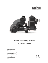
Performance chart
Makeup capacity in m3/hour
Makeup pressure in bar

Installation
Fillcontrol Auto — 06.07.2016 - Rev. B English —
15
6 Installation
DANGER
Risk of serious injury or death due to electric shock.
If live parts are touched, there is risk of life-threatening injuries.
• Ensure that the system is voltage-free before installing the device.
• Ensure that the system is secured and cannot be reactivated by other persons.
• Ensure that installation work for the electric connection of the device is carried out by an electrician, and in compliance with
electrical engineering regulations.
CAUTION
Risk of injury due to pressurised liquid
If installation, removal or maintenance work is not carried out correctly, there is a risk of burns and other injuries at the connection
points, if pressurised hot water or hot steam suddenly escapes.
• Ensure proper installation, removal or maintenance work.
• Ensure that the system is de-pressurised before performing installation, removal or maintenance work at the connection points.
CAUTION
Risk of burns on hot surfaces
Hot surfaces in heating systems can cause burns to the skin.
• Wear protective gloves.
• Please place appropriate warning signs in the vicinity of the device.
CAUTION
Risk of injury due to falls or bumps
Bruising from falls or bumps on system components during installation.
• Wear personal protective equipment (helmet, protective clothing, gloves, safety boots).
Note!
Confirm that installation and start
-up have been carried out correctly using the installation, start-up and maintenance
certificate. This action is a prerequisite for the making of warranty claims.
–
Have the Reflex Customer Service carry out commissioning and the annual maintenance.

I
nstallation
16
— English Fillcontrol Auto — 06.07.2016 - Rev. B
6.1 Installation conditions
6.1.1 Incoming inspection
Prior to shipping, this device was carefully inspected and packed. Damages during transport cannot be excluded.
Proceed as follows:
1. Upon receipt of the goods, check the shipment for
• completeness and
• possible transport damage.
2. Document any damage.
3. Contact the forwarding agent to register your complaint.
6.2 Preparatory work
Preparing the device installation:
• Frost-free, well-ventilated room.
– Room temperature range: 0 °C to 45 °C.
• Filling connection.
– If necessary, provide a DN 15 filling connection according to DIN 1988 T 4.
• Electric connection: 230 V~, 50 Hz, 16 A with upstream ELCB: Tripping current 0.03 A.

Installation
Fillcontrol Auto — 06.07.2016 - Rev. B English —
17
6.3 Execution
ATTENTION
Damage due to improper installation
Additional device stresses may arise due to the connection of pipes or system equipment.
• Ensure that pipes are connected from the device to the system without stresses being induced.
• If necessary, provide support structures for the pipes or equipment.
Note!
Starting up of the pump causes vibration in the device. This transfers loud noises into
the system pipes.
–
Connect the pipes to the device using flexible connections.
In systems with a diaphragm expansion tank, the device must be installed in the vicinity of the tank. To ensure that the required filling
pressure for water make-up is recorded by the pressure transducer in the device. The filling pressure depends on the minimum operating
pressure of the facility system. For calculating the minimum operating pressure,see chapter 7.2 "Determining the P0 minimum operating
pressure for the controller" on page 26 .
Proceed as follows for the installation:
1. Position the device.
2. Create the water-side connections of the device to the system.
– Use connections with the same dimensions at the device for all lines.
3. If required, create the interfaces according to the terminal plan.

Installation
18
— English Fillcontrol Auto — 06.07.2016 - Rev. B
6.3.1 Floor mounting
Floor mounting
The device is installed on the floor. Select the attachment means
according to the
floor properties and the weight of the device.
During installation, ensure that:
–
The device is installed sufficiently close to the diaphragm
expansion tank. You ensure so that the "PIS" pressure
sensor is able to measure the filling pressure.
–
The fixtures can be operated.
–
The feed connections of the pipes are not adversely
affected.
Installation with user-supplied system separator tank
Note during the installation:
–
The ambient temperatures must not exceed 45 °C.
–
The correct pipeline length (see table).
–
The "WC" makeup connection must be at least 100 mm
above the "PU" pump intake connection.
–
The correct minimum diameter of the intake line and the
pressure line (see table).
–
The provision of the EN 1717 standard are met.
–
A nominal volume of ≤ 200 l is recommended for the
system separator tank.
–
An overflow with sufficient dimensions according to the
maximum intake is installed.
–
A shut-off valve is installed in the intake line to the system
separator tank.
1 "PU" pump 3 "BT" system separator
vessel
2 "PIS" pressure
transducer
4 "ST" dirt trap
Nominal diameters of the intake and pressure lines depending on the required makeup pressure
Makeup pressure
> 3.7 bar
≤ 3.7 bar
Pressure line ≤ 10 m DN 32 DN 40
Pressure line ≤ 2 m DN 32 DN 40
Note!
For installation at the same level, open the Customer menu to set the "P
0" minimum operating pressure to the "p0" initial
pressure of the "MAG" diaphragm expansion tank, otherwise, you must correct with "hst"
,see chapter 7.2 "Determining
the P
0 minimum operating pressure for the controller" on page 26 .

Installation
Fillcontrol Auto — 06.07.2016 - Rev. B English —
19
6.3.2 Hydraulic connection
6.3.2.1 Connection to the facility system
Note!
Starting up of the pump causes vibration in the device. This transfers loud noises into the system pipes.
–
Connect the pipes to the device using flexible connections.
Connection to the facility system with a system separator tank for the make-up with fresh water.
1 "Fillsoft" softening system, see chapter 4.6 "Optional
equipment and accessories" on page 13 .
4 "BT" system separator tank
2 Contact water meter, optional accessory 5 "ST" dirt trap
3 "PU" pump WC Make-up lines
• Intake line to pump
• Pressure line to the facility system
Comply with the following requisites for the installation and connection of an open system separator tank.
– Make-up temperatures up to 70° C
– Pipeline lengths, see chapter 6.3.1 "Floor mounting" on page 18 .
– Outlet from the system separator tank at least 100 mm above the intake connection of the "PU" pump.
– "WC" intake line to "PU" pump with constant incline to the system separator tank.
Note!
At make
-up temperatures > 70 °C and the use in facility systems without system separator tanks, you must plan according
to the local conditions, see chapter
12.1 "Reflex Customer Service" on page 47 .

Installation
20
— English Fillcontrol Auto — 06.07.2016 - Rev. B
6.4 Switching and make-up variants
Example diagram for a pressure-dependent make-up with water in a solar installation with diaphragm expansion tank.
1 "PU" pump WC Make-up lines
• Intake line to "PU" pump
• Pressure line to the facility system
2 "BT" system separator tank DN Nominal diameter of the make-up lines
3 "ST" dirt trap
In facility systems with a diaphragm expansion tank, the "PIS" pressure transducer in the device monitors the make-up with fresh water.
When the required filling pressure for water make-up drops below the minimum value, the pressure transducer sends a signal to the
device controller. The controller activates the pump. Fresh water from the system separator tank is added to the system.
Proceed as follows:
1. In the Customer menu, set the device to "Magcontrol", see chapter 9.2.1 "Customer menu" on page 38 .
2. Connect the pressure line near the connection to the diaphragm expansion tank.
– This ensures that the "PIS" pressure transducer detects the filling pressure required for the make-up with fresh water.
– For calculating the filling pressure,see chapter 7.2 "Determining the P0 minimum operating pressure for the controller" on
page 26 .
3. Do not use nominal diameters below the specified diameters for the "WC"make-up lines, see chapter 6.3.1 "Floor mounting" on
page 18 .
– You will avoid an undesired cycling of the make-up.
4. In solar plants, use the "BT" system separator tank to prepare the water/glycol mixture.
– Size the system separator tank with at least 1.5 times the system volume.
/