
2005 Assembly & Operation Manual
Models: 810SS & 8611SS
A
64060 5/2/05

INTRODUCTIONS/TABLE OF CONTENTS
2
64060 (2005-810&8611SkidSteer).doc
Congratulations on purchasing the most advanced, all-season skid steer snowplow available! The Blizzard Power
Plow® snowplow is clearing new trails for innovative design, rugged durability, quality craftsmanship and superior
performance. Our exclusive products are manufactured and tested in Michigan’s Upper Peninsula, the snow
capital of the Midwest. With an annual snowfall averaging over 250" we couldn’t imagine building snow removal
products anywhere else!
TABLE OF CONTENTS
Safety ............................................... 3
Operation.......................................... 4
Unpacking & Inspection.................... 5
Technical Specifications ................... 6
Torque Specifications ....................... 7
Moldboard Assembly ........................ 8
A-Frame Assembly ........................... 9
Electrical Assembly........................... 12
Mounting & Dismounting
Instructions ....................................... 19
Testing your Plow ............................. 20
Maintenance ..................................... 21
Troubleshooting................................ 22
Moldboard & Wing Parts................... 24
A-Frame, Pivot Beam &
Manifold Parts................................... 26
Harnesses, Accessories & Kits......... 28
Warranty ........................................... 30

SAFETY
3
64060 (2005-810&8611SkidSteer).doc
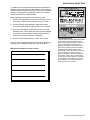
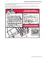
WARNING Prior to operating your Power Plow® snowplow, review the WARNING! label at
the passenger’s side rear of the moldboard (shown below).
CAUTION NOTE: Read and understand all warnings indicated in this manual prior to operating the
snowplow. Warnings and cautions in the manual are indicated by the icons shown at left.
NOTE: If at any time the safety labels become illegible, promptly replace them.

OPERATION
4
64060 (2005-810&8611SkidSteer).doc
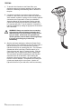
Your Blizzard Power Plow® snowplow is the most advanced and
versatile snowplow on the market. The easy-to-use controls
allow you to automatically adjust the plow blade and wings into
an infinite number of plowing positions. Review the illustrations
below to determine the best position for your plowing needs.
A.
Compact Position
(8' or 8'-6" Blade Width)
• Primary position when transporting the
snowplow
• For use in heavy snow conditions with poor
visibility, initial clearing and tight quarters
• Ideal application: Residential driveways,
small roads
B. WidePass™ Position
(10' or 11'-3" Blade Width)
• Primary position for clearing large surfaces
• For use in light snow conditions with good
visibility, final clearing and clean-up
• Ideal application: Large parking lots,
widening roadways
C. BucketBlade™ Position
(9'-3" or 9'-10" Blade Width)
• Primary position for transporting snow
• For use in initial clearing with decent
visibility, transporting large volumes of snow,
final clean-up
• Ideal application: Roadway intersections
D. WidePass™ Position Angled with
Wing Forward
• Primary position for accelerated angled
plowing
• For use in directional plowing, cornering,
diverting snow away from objects or
buildings
• Ideal application: Plowing adjacent to
buildings, driveway /road intersections
D.
C.
B.
A.

UNPACKING & INSPECTION
5
64060 (2005-810&8611SkidSteer).doc
Your Blizzard Power Plow® snowplow has been packaged to
withstand transit and weather related damage. Fully inspect all
components upon receipt of your plow. In the event of shipping
damage or missing parts, immediately contact our Customer
Service Department at 1-888-680-8600.
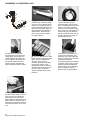
Begin unpacking and inspection in the following order:
1. Remove the shipping document from the end panel of the
pallet wrap. Retain all documentation for your records.
2. All wood framing and polyethylene material should be
removed from the pallet for easy access to the snowplow.
3. Due to the odd shaped components and size of several
assembly parts, various cable ties and corrugated material
are used for scratch resistance and package orientation.
Please remove these items prior to assembly.
4. Place the main blade assembly on a flat, level surface.
Once you have inspected all parts and removed all packaging
materials, your snowplow is ready to be fully assembled.
Retain this information for your records.
Pallet Wrap End Panel
The tear-resistant, woven polyethylene pallet
wrap contains a moisture barrier to help
protect all packaged components and keep
out the most inclement weather during
shipping and storage. The end panel of the
pallet cover contains important information
regarding the snowplow model and the
plow’s serial number. Both of these numbers
are given together. The first three (four)
digits of the number indicated is always the
plow model – 810 (or 8611) and the entire
number is the serial number (Ex: 810-00001
or 8611-00001). The shipping document is
also attached to the end panel. Be sure to
retain this list for your records.
DATE OF PURCHASE:
DEALER/DISTRIBUTOR:
DEALER PHONE NUMBER:
SNOWPLOW SERIAL NUMBER:
HYDRAULIC PUMP SERIAL NUMBER:

TECHNICAL SPECIFICATIONS
6
64060 (2005-810&8611SkidSteer).doc
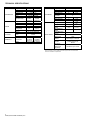
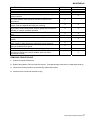
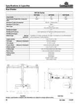
PART SPECIFICATION 810 8611
Length 96” (8’) 102” (8’6”)
Thickness 12 gauge 11 gauge
Height 31” 34”
Reinforcement 4 ribs @ 1/4"
Cutting Edge 1/2” x 6” 5/8” x 6”
Finish Powder Coat White
MOLDBOARD
Trip Mechanism
(4) 3/8”
hooked
extension
(6) 3/8”
hooked
extension
Length 12” 23”
Thickness 11 gauge 7 gauge
Height 31” 34”
Reinforcement 1 rib @ 1/4"
Cutting Edge
1/4” X 10”
T1
3/8” X 12-
1/2” T1
WINGS
Finish Powder Coat White
Material 1/4” & 5/16” Mild Steel
Cover
1/4” Mild Steel w/ non-skid
texture
A-FRAME
Finish Powder Coat Black
Construction
Clear
Anodized
Aluminum
Gold
Anodized
Aluminum
MANIFOLD
Valves Electro-hydraulic cartridge
PART SPECIFICATION 810 8611
Angle Cylinders
2
Stroke 10”
Ram Diameter 1-3/4” 2”
Bore Diameter 2” 2-1/4”
Slide Box
Cylinders
2
Stroke 13-15/16” 18-7/16”
Ram Diameter 1” 1-1/8”
CYLINDERS
Bore Diameter 1-1/2” 1-3/4”
Weight* 950 lbs.
1470
Lbs.
Compact Width 96” (8’) 102” (8’-6”)
WidePass™
Width
120”
(10’)
132”
(11’-3”)
BucketBlade™
Width
111”(9’-3”) 118”(9’-10”)
Adjustable Plow
Shoes
(2) Heavy-Duty Cast Steel
Mount
Mechanism
Universal Attachment
Plate
Standard Control
Station
Pistol Grip w/ 3 switches
Integrated
Control
(Optional)
Auxiliary Harness w/
Diodes
PLOW SPECS.
Anti-Trip
Mechanism
(Optional)
One-Piece Trip-Lock bar
Blizzard Corporation reserves the right, under its Continuous Improvement Policy, to
change construction or design details and furnish equipment when so altered without
reference to illustrations or specifications.

TORQUE SPECIFICATIONS
7
64060 (2005-810&8611SkidSteer).doc
Grade Identification Marking for J429-Grade 5 Bolt Grade Identification Marking for J429-Grade 8 Bolt
SAE J429 – Grade 5 SAE J429 – Grade 8
Tightening Torque Tightening Torque
Nominal
Thread Size
Clamp Loads
(lbs)
“Lubricated” “Dry”
Nominal
Thread Size
Clamp Loads
(lbs)
“Lubricated” “Dry”
1/4-20 2,000 6 ft-lbs 8 ft-lbs 1/4-20 2,850 9 ft-lbs 12 ft-lbs
5/16-18 3,350 13 ft-lbs 18 ft-lbs 5/16-18 4,700 18 ft-lbs 25 ft-lbs
3/8-16 4,950 23 ft-lbs 31 ft-lbs 3/8-16 6,950 32 ft-lbs 44 ft-lbs
7/16-14 6,800 37 ft-lbs 50 ft-lbs 7/16-14 9,600 53 ft-lbs 70 ft-lbs
1/2-13 9,050 57 ft-lbs 75 ft-lbs 1/2-13 12,800 80 ft-lbs 107 ft-lbs
9/16-12 11,600 82 ft-lbs 109 ft-lbs 9/16-12 16,400 115 ft-lbs 154 ft-lbs
5/8-11 14,500 113 ft-lbs 151 ft-lbs 5/8-11 20,300 159 ft-lbs 211 ft-lbs
3/4-10 21,300 200 ft-lbs 266 ft-lbs 3/4-10 30,100 282 ft-lbs 376 ft-lbs
7/8-9 29,435 321 ft-lbs 430 ft-lbs 7/8-9 41,550 454 ft-lbs 606 ft-lbs
1-8 38,600 482 ft-lbs 640 ft-lbs 1-8 54,540 680 ft-lbs 900 ft-lbs
Grade Identification Marking for Metric-Grade 8.8 Bolt Grade Identification Marking for Metric-Grade 10.9 Bolt
Metric Class 8.8 Metric Class 10.9
Tightening Torque Tightening Torque
Diameter
(mm)
Clamp Loads
(Pounds)
“Lubricated” “Dry”
Diameter
(mm)
Clamp Loads
(Pounds)
“Lubricated” “Dry”
5 1,389 3 ft-lbs 5 ft-lbs 5 1,987 5 ft-lbs 7 ft-lbs
6 1,965 6 ft-lbs 8 ft-lbs 6 2,812 8 ft-lbs 11 ft-lbs
7 2,826 10 ft-lbs 13 ft-lbs 7 4,044 14 ft-lbs 19 ft-lbs
8 3,579 14 ft-lbs 19 ft-lbs 8 5,121 20 ft-lbs 27 ft-lbs
10 5,672 28 ft-lbs 37 ft-lbs 10 8,116 40 ft-lbs 53 ft-lbs
12 8,243 49 ft-lbs 65 ft-lbs 12 11,796 70 ft-lbs 92 ft-lbs
14 11,246 77 ft-lbs 103 ft-lbs 14 16,092 111 ft-lbs 148 ft-lbs
16 15,882 125 ft-lbs 167 ft-lbs 16 21,970 173 ft-lbs 231 ft-lbs
18 19,423 172 ft-lbs 229 ft-lbs 18 26,868 238 ft-lbs 317 ft-lbs
20 24,784 244 ft-lbs 325 ft-lbs 20 34,284 338 ft-lbs 450 ft-lbs
37° JIC Flare Torque Values
Turns Size
Ft-lbs
min.max
Assembly steps
N/A -02 6-7
N/A -03 8-9
2 -04 11-12
2 -05 14-15
1-1/2 -06 18-20
1-1/2 -08 36-39
1-1/2 -10 57-63
1-1/4 -12 79-88
1 -14 94-103
1 -16 108-113
1 -20 127-133
1 -24 158-167
1 -32 245-258
1. Make sure the tubing and threads are
clean.
2. Lubricate the threads with 10W hydraulic
oil.
3. Hand tighten the nut/sleeve to approx. 30
in-lbs.
4. Make alignment marks on the nut and
fitting.
5. Tighten to turn or torque specification.
6. When fully tightened, make a 2
nd
set of
alignment marks at the fully tighten
positioned.
NOTE: Torque values specified are for
threads lubricated with 10W hydraulic oil.
Over tightening will reduce the clamping force
resulting in loss of seal and reduction of flow.
O-Ring Boss Torque Values
Size
Ft-lbs
min.max
Assembly steps
-02 6-7
-03 8-10
-04 13-15
-05 17-21
-06 22-25
-08 40-43
-10 43-57
-12 68-75
-14 90-99
-16 112-123
-20 146-200
-24 154-215
-32 218-290
1. Verify the port, o-ring, sealing surfaces and threads
are clean and free of damage.
2. Lubricate the threads and the o-ring with 10W
hydraulic oil.
3. For an adjustable O.R.B., completely back off the lock
nut and washer.
4. Hand tighten the fitting until it contacts the port
spotface. Point the elbow or tee in the desired
direction and hold.
5. Torque to specification.
NOTE: Torque values specified are for threads lubricated
with 10W hydraulic oil.

MOLDBOARD ASSEMBLY
8
64060 (2005-810&8611SkidSteer).doc
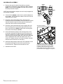
1. Remove dust cap from both of the slide box cylinders
located at the center/rear of the moldboard. Attach adapters
(60007 on the 810SS and 60272 on the 8611SS) to each of
the base ports and rod ports.
NOTE: All of the hydraulic adapters can be found packaged with
the manifold assembly.
2. Connect hoses (60224) to each of the hydraulic adapters on
the cylinders. NOTE: Review the label on each hose for the
appropriate part number
3. Position the pivot beam and A-frame, near the mount
locations at the rear of the blade. Place the slide box cylinder
hydraulic hoses through the rubber grommet openings on
each side of the front face of the pivot beam.
4. Position the pivot beam between the two support ribs until
the connecting points on the beam align with those on the
plow. Insert clevis pin (50069) through each mounting hole
and secure with cotter pins (61357).
5. Hook each extension spring to the receiving holes on the
pivot beam and attach the opposite end of the spring to its
respective spade bolts. Install the spade bolts through the
extension spring mounting angle on the top rear of the blade.
Secure spade bolts with a 5/8" flat washer and a 5/8"-11
nylock nut. Tighten each nut until a piece of paper can pass
between the 3rd & 4th coils on the spring.
6. Install the blade guides at each end of the moldboard. Insert
the capscrew through the holes at the top of the wing
reinforcement rib. Tighten all screws with lock nuts.
7. Assemble the A-Frame.
Skid Steer Adapters
Feed each group of hoses, 2 per side,
through the grommets in the pivot beam.
Positioning the hoses through the pivot
beam supports the hoses while in use and
prevents them from dragging on the ground.
9
16
9
16
60005
60007
9
16
9
16
60272
9
16
9
16

A-FRAME ASSEMBLY
9
64060 (2005-810&8611SkidSteer).doc
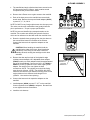
1. The manifold and angle cylinders have been secured to the
A-Frame at the factory; however, each contains several
components that you will need to install.
2. Remove the A-Frame cover to gain access to the manifold.
3. Each of the hose ports on the manifold are covered with
stretch wrap. Remove the wrap and install adapter (60272)
to ports #1, 2, 7, 8, 9 & 10.
NOTE: DO NOT let any foreign objects enter into the open ports.
The valves can become contaminated and greatly hinder the
plow’s performance. Torque to proper specifications.
NOTE: All ports are identified by a stamped number on the
manifold. The numbers also identify the hydraulic functions,
which can be referenced on the label under the manifold cover.
4. Route the hydraulic hose groupings from the pivot beam to
the access holes located on the sides of the a-frame.
Connect the hoses to their respective adapters on the
manifold.
CAUTION: When handling the manifold, hold the
manifold at the sides of the block. Never handle the
manifold by coils. Doing so can cause a solenoid
cartridge to bend, causing the cartridge to stick when
activated.
5. Remove the dust cap from both of the hydraulic angle
cylinder ports and attach a 90° adjustable elbow adapter
(60005) to each port. Each adapter should be angled toward
the top of the moldboard. Connect one 3/8" x 26" (60223 or
60224 36" for 8611) hydraulic hose to each angle cylinder
adapter. Be careful not to over tighten the hose
connections. NOTE: The cylinder ports should be facing
away from the A-frame. NOTE: The 810SS & 8611SS A-
frame are the same but use different mounting points for the
angle cylinders due to different stroke length on the
cylinders. Use caution when replacing.
6. Connect the hoses to their respective adapters on the
manifold.
7. Install adapters (60089) to ports “P” & “T” on the manifold.
Connect hydraulic hose (60086) to adapters. Be careful not
to over tighten the hose connections.
8. Install the wire harness.
Ports #1, 2, 7, 8, 9 &10.
Ports “T” & “P”.
Angle Cylinder Mounting
CV2
8
7
9
10
CV4 PC
2
1
S9 S1 S5
CV5
PT
8611SS USES
OUTER HOLES
810SS USES
INNER HOLES

HYDRAULIC GUIDE
10
64060 (2005-810&8611SkidSteer).doc

SCHEMATIC
11
64060 (2005-810&8611SkidSteer).doc
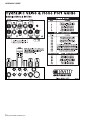
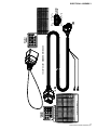
NOTE: Where applicable, Model 8611SS values are in parenthesis.
HYDRAULIC SCHEMATIC
S5
P T
PC
50 PSI
RV2
1500 PSI
50 PSI
S10
RV1
1700 PSI
CV1
8
S4
S9
50 PSI
S3
CV2
7
3000 PSI
LEFT ANGLE
1
RV5
2
LEFT SLIDE BOX
RIGHT ANGLE
S2
50 PSI
S1
50 PSI
RV3
1500 PSI
CV3
9
CV4
10
RIGHT SLIDE BOX
RV4
1700 PSI
E
S4
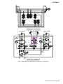
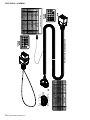
ELECTRICAL SCHEMATIC
S4
S9
S1
S2
J
K
S3
S10
F
H
G
S9
S10
S1
S2
A
B
D
C
S5
S3
S5
(BOTTOM) (TOP)
CV5
5 PSI
(2650 PSI)
(2800 PSI)
(2650 PSI)
(2800 PSI)

ELECTRICAL-ASSEMBLY
12
64060 (2005-810&8611SkidSteer).doc
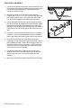
1. Connect the manifold coil harness to the plow harness. Feed
the opposite end of the plow harness through the top access
hole in the A-frame (same as 3/4" tank hydraulic hose)
located on the driver’s side.
2. Attach the grounds on the coil wire harness and plow
harness with a 3/8"-16 x 1-1/2" hex cap screw and 3/8" tooth
lock washer to the A-frame. Secure the wires with a lock
nut. Review the diagram for the proper ground location.
3. Connect the plow harness to the vehicle harness, and then
the vehicle harness to the pistol grip control harness. Attach
the ground wire from the vehicle harness to the cab of the
skid steer. The pink/black power wire connects to a switched
power source (on and off with ignition) with a minimum of 12
volts.
4. Position the vehicle harness mount bracket in an accessible
location for easy on-and-off installation inside the skid steer.
Secure the vehicle side harness in the notch on the bracket.
5. Position the control harness mount bracket vertically or
horizontally for user preference inside the skid steer. Secure
with hardware provided. Position the pistol grip control into
the bracket and “twist-lock” it into place. NOTE: Install the
bracket so it does not interfere with any safety devices that
might rotate in front of the operator.
6. Complete the assembly by attaching the A-frame cover.
Align the holes in the cover with those on the A-frame and
secure it with 3/8"-16 x 1-1/2" hex cap screws and 3/8"
washers.
7. Mount your plow to the skid steer, and then test all functions.
Control Mount Bracket (70048)
MANIFOLD
MOUNT HOLES
GROUND
MOUNT
HOLE

CONTROL SCHEMATIC
13
64060 (2005-810&8611SkidSteer).doc
A
B
A
B
A
B
A
B
A
B
A
B
A
B
GROUND
GROUND
GROUND
GROUND
GROUND
GROUND
L. RETRACT
L. EXTEND
R. ANGLE
R. RETRACT
L. ANGLE
R. EXTEND
RED
GROUND
DUMP SOLENOID
BLUE
BLACK
BLUE/BLACK
GREEN
RED/BLACK
RED/WHITE
BLUE/WHITE
BLACK
PINK/BLACK
BLUE
BLACK
BLUE/BLACK
GREEN
RED/BLACK
RED/WHITE
BLUE/WHITE
BLACK
PINK/BLACK
LEFT ANGLE
RIGHT ANGLE
LEFT BOX EXTEND
LEFT BOX RETRACT
RIGHT BOX EXTEND
RIGHT BOX RETRACT
BLUE
BLACK
BLUE/BLACK
GREEN
RED/BLACK
RED/WHITE
BLUE/WHITE
BROWN
M1 M2 C3C2C1 C4
SWITCH #2
SWITCH #3
SWITCH #1
BLACK
S2
S3
S1
S4
S10
S9
S5
-
12V
+
CUSTOMER
SUPPLIED
RED
RED
RED
RED
RED
RED
A
G
H
E
J
F
K
A
G
H
E
J
F
K
9
14
3
8
4
13
9
14
3
8
4
13
D
11
G
H
E
J
F
K
D
C
A
POWER
POWER
POWER
G
H
E
J
F
K
D
C
A
4
4
4
6
6
6
2
2
2
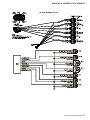
SS PISTOL GRIP CONTROL HARNESS SCHEMATIC (62131);
INCLUDES 62132, 62133, 62134, 62135, 62136, 62210, 62211&
62219

ELECTRICAL- ASSEMBLY
14
64060 (2005-810&8611SkidSteer).doc
RED/WHITE 18
COLOR
K
E
G
J
H
F
A
PIN #
C
D
B
FUNCTION AWG
18
18
18
18
18
18
POWERPINK/BLACK
RED/BLACK
BLUE/WHITE
BLUE/BLACK
BLUE
GREEN
BLACK
GROUND (JUMPER)
RIGHT ANGLE
LEFT ANGLE
LEFT BOX RETRACT
LEFT BOX EXTEND
RIGHT BOX RETRACT
RIGHT BOX EXTEND
C
B
A
CONNECTOR
LOOKING AT
G
F
H
E
D
K
J
END VIEW
CONTROL
18
BLACK
GROUND (JUMPER)
18
(JUMPER)
B
A
C
K
V
I
E
W
O
F
S
W
I
T
C
H
#
1
T
O
P
1
2
3
4
5
6
BACK VIEW
OF SWITCH #2
TOP
12
34
56
B
A
CK
VI
E
W
O
F
S
W
I
T
CH
#
3
T
O
P
12
3
4
56
BACK VIEW OF SKID STEER SWITCH PLATE
C1
SWITCH # 1
1
3
4
6
5
2
PIN # COLOR AWG
18
18RED/BLACK
RED/WHITE 18
6"
84"
84"
LENGTH
PINK/BLACK
NOTE: NO NUMBERS ON SWITCH
SWITCH # 2
1
3
4
6
5
2
PIN # COLOR AWG
18
18BLUE/BLACK
BLUE/WHITE 18
6"
84"
84"
LENGTH
PINK/BLACK
NOTE: NO NUMBERS ON SWITCH
SWITCH # 3
1
3
4
6
5
2
PIN # COLOR AWG
18
18GREEN
BLUE
18
6"
84"
84"
LENGTH
PINK/BLACK
NOTE: NO NUMBERS ON SWITCH
(USE THIS CHART TO FIND TOP) (USE THIS CHART TO FIND TOP)(USE THIS CHART TO FIND TOP)
N/AN/A N/A
SS CONTROL HARNESS (62210, 62211& 62219)

ELECTRICAL ASSEMBLY
15
64060 (2005-810&8611SkidSteer).doc
COLOR
K
E
G
J
H
F
A
PIN #
C
D
B
FUNCTION AWG
RED/WHITE
18
18
18
18
18
18
18
POWER (POS)
PINK/BLACK
RED/BLACK
BLUE/WHITE
BLUE/BLACK
BLUE
GREEN
BLACK GROUND
RIGHT ANGLE
LEFT ANGLE
LEFT BOX RETRACT
LEFT BOX EXTEND
RIGHT BOX RETRACT
RIGHT BOX EXTEND
F
A
K
J
H
G
E
D
CONNECTOR
LOOKING AT
END VIEW
C
B
18BLACK
GROUND (NEG)
18
FUNCTION
4
5
6
7
PIN #
2
1
COLOR AWG
3
8
9
10
11
12
13
14
GREEN
N/A
N/A
N/A
BLACK GROUND 18
N/A N/A
N/A N/A
N/A N/A
BLUE
RIGHT ANGLE
LEFT ANGLE
18
18
N/A
N/A
N/A N/A N/A
N/A N/A
N/A N/A
RED/BLACK
BLUE/BLACK
RIGHT BOX RETRACT
LEFT BOX RETRACT
18
18
N/A N/A N/A
N/A N/A N/A
RED/WHITE
BLUE/WHITE
RIGHT BOX EXTEND
LEFT BOX EXTEND
18
18
M1
NOTE: REMOVE EXCESS RUBBER
FROM TERMINALS NOT USED
LOOKING AT
CONNECTOR
END VIEW
BLIZZARD PLUG (SQUARE)
C2
N/A N/A N/A
N/A
N/A N/A
SS VEHICLE HARNESS (62132, 62133)
LOOKING AT
CONNECTOR
END VIEW

ELECTRICAL- ASSEMBLY
16
64060 (2005-810&8611SkidSteer).doc
F
A
K
J
H
G
E
D
CONNECTOR
LOOKING AT
END VIEW
C
B
COLOR
K
E
G
J
H
F
A
PIN #
C
D
B
FUNCTION AWG
RED/WHITE
18
18
18
18
18
18
18
N/A
18
N/A
DUMP SOLENOID
N/A
BROWN
RED/BLACK
BLUE/WHITE
BLUE/BLACK
BLUE
GREEN
BLACK GROUND
RIGHT ANGLE
LEFT ANGLE
LEFT WING RETRACT
LEFT WING EXTEND
RIGHT WING RETRACT
RIGHT WING EXTEND
LOOKING AT
CONNECTOR
END VIEW
FUNCTION
4
5
6
7
PIN #
2
1
COLOR AWG
3
8
9
10
11
12
13
14
GREEN
N/A
N/A
N/A
BLACK GROUND 18
N/A N/A
N/A N/A
N/A N/A
BLUE
RIGHT ANGLE
LEFT ANGLE
18
18
N/A
N/A
N/A N/A N/A
N/A N/A
N/A N/A
RED/BLACK RIGHT BOX RETRACT 18
BROWN PUMP SOLENOID 18
N/A N/A N/A
N/A N/A N/A
RED/WHITE
BLUE/WHITE
RIGHT BOX EXTEND
LEFT BOX EXTEND
18
18
BLIZZARD PLUG (SQUARE)
M2
C3
N/A N/A N/A
N/A N/AN/A
SS PLOW HARNESS (62134, 62135)
LOOKING AT
CONNECTOR
END VIEW

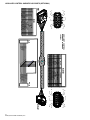
ELECTRICAL-ASSEMBLY-COIL HARNESS
17
64060 (2005-810&8611SkidSteer).doc
SS COIL HARNESS (62136)

AUXILIARY CONTROL HARNESS W/ DIODES (OPTIONAL)
18
64060 (2005-810&8611SkidSteer).doc
F
A
K
J
H
G
E
D
C
B
COLOR
K
E
G
J
H
F
A
PIN #
C
D
B
FUNCTION AWG
RED/WHITE
18
18
18
18
18
18
18
N/A
18
N/A
N/A
N/A
N/A
N/A
RED/BLACK
BLUE/WHITE
BLUE/BLACK
BLUE
GREEN
BLACK
BROWN PUMP SOLENOID
GROUND
RIGHT ANGLE
LEFT ANGLE
LEFT BOX RETRACT
LEFT BOX EXTEND
RIGHT BOX RETRACT
RIGHT BOX EXTEND
C4
C3-2
C3-2
BROWN - PIN B
BLACK - PIN D
GREEN - PIN E
BLUE - PIN F
BLUE/BLACK - PIN G
BLUE/WHITE - PIN H
RED/BLACK - PIN J
RED/WHITE - PIN K
BLACK
GREEN
BLUE
BLUE/BLACK
BLUE/WHITE
RED/BLACK
RED/WHITE
C4
D1
SP-3
SP-2
SP-4
SP-5
SP-6
SP-7
D2
D3
D4
D5
D6
RED/WHITE
18
COLOR
K
E
G
J
H
F
A
PIN #
C
D
B
FUNCTION AWG
18
18
18
18
18
18
N/A
N/AN/A
RED/BLACK
BLUE/WHITE
BLUE/BLACK
BLUE
GREEN
BLACK
N/A N/A
GROUND (JUMPER)
RIGHT ANGLE
LEFT ANGLE
LEFT BOX RETRACT
LEFT BOX EXTEND
RIGHT BOX RETRACT
RIGHT BOX EXTEND
C
B
A
G
F
H
E
D
K
J
N/A
N/A N/A
N/A
C3-2
C4
AUXILIARY CONTROL
HARNESS W/ DIODES
(62166)

MOUNTING & DISMOUNTING INSTRUCTIONS
19
64060 (2005-810&8611SkidSteer).doc
Prior to operating your Power Plow® snowplow, review the Mounting and Dismounting Instructions label on the
back of the driver’s side moldboard.
NOTE: If at any time the Mounting and Dismounting Instructions label, or any other label attached to your
snowplow become illegible, promptly replace them.

TESTING
20
64060 (2005-810&8611SkidSteer).doc
1. To test all of the functions on the Power Plow, your
snowplow needs to be properly attached to the skid steer.
Refer to the Mounting & Dismounting label on the back of
the plow.
2. Complete the hydraulic connections with the skid steer
turned off. Note: Due to the various make and model skid
steer available, hydraulic couplings for the auxiliary hydraulic
connections are not provided. Consult your skidsteer’s
Operation Manual for the appropriate couplings needed.
Connect the couplings to the hoses for the pressure port
(“P”) and the tank port (“T”)on the manifold. Complete the
hydraulic installation by making the appropriate connections
at the skid steer.
WARNING: Always use caution when connecting
high-pressure hydraulic fittings. Hydraulic fluid
under pressure can puncture skin causing serious
injury or death. In the event of a hydraulic leak,
relieve hydraulic pressure before loosening fittings.
If injured, seek emergency medical help
immediately.
3. Start the skid steer and begin to initiate the Power Plow’s
blade functions. Note: Depending on the skid steer model, it
may be necessary to turn on the skid steer’s auxiliary
hydraulic switch prior to operating the plow. The left switch
operates the driver’s side wing. Push the switch “up” to
extend the wing and “down” to retract the wing. Push the
center switch “up” to angle left and “down” to angle right.
The right switch operates the passenger’s side wing and
works the same as the left switch. Upon initiating the
switches on the pistol grip control, you may notice a plow
function is slow or delayed. The hydraulic fluid is filling the
cylinders and replacing air in the system. Monitor the
hydraulic fluid level in your skid steer, and fill as necessary.
Page is loading ...
Page is loading ...
Page is loading ...
Page is loading ...
Page is loading ...
Page is loading ...
Page is loading ...
Page is loading ...
Page is loading ...
Page is loading ...
Page is loading ...
Page is loading ...
-
 1
1
-
 2
2
-
 3
3
-
 4
4
-
 5
5
-
 6
6
-
 7
7
-
 8
8
-
 9
9
-
 10
10
-
 11
11
-
 12
12
-
 13
13
-
 14
14
-
 15
15
-
 16
16
-
 17
17
-
 18
18
-
 19
19
-
 20
20
-
 21
21
-
 22
22
-
 23
23
-
 24
24
-
 25
25
-
 26
26
-
 27
27
-
 28
28
-
 29
29
-
 30
30
-
 31
31
-
 32
32


Blizzard Entertainment 8611SS User manual
- Type
- User manual
- This manual is also suitable for
Ask a question and I''ll find the answer in the document
Finding information in a document is now easier with AI
Other documents
-
Brinly-Hardy PP-51BH User guide
-
 Land Pride RBT4096 User manual
-
Land Pride RBT40 Series Quick start guide
-
 Land Pride RBT40 User manual
-
FirstTrax 84200 Installation guide
-
 SnowDogg MD75 Owner's manual
-
 Sno-Way HTVG100000 Owner's manual
-
FirstTrax 84200 User manual
-
 T & S Brass & Bronze Works PG-35AV-CH01 Datasheet
-
All-Power APW5102 Owner's manual


