Page is loading ...
For Customer Use:
Enter below the Model No. and Serial
No. which are located either on the rear,
bottom or side of the cabinet. Retain this
information for future reference.
Model No.
Serial No.
LET0052-001A
[J]
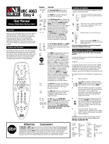
INSTRUCTIONS
RX-772VBK
AUDIO/VIDEO CONTROL RECEIVER
O
N
S
C
R
E
E
N
C
O
N
T
R
O
L
RM-SR772U REMOTE CONTROL
/SAT POWER
CD
DISC
CD
TRACK
SOUND
CONTROL
VCR
POWER
AUDIO
POWER
SLEEP
VIDEO TAPEVCR
TV
SOUND
TEST REAR
SEA MODE SURR MODE
FM/AM PHONOCD
546
213
87
/P
9
0
10
AUDIO/TV
/VCR
MENU
EXIT
MENU
TAPE VCR
CONTROL
VOLUME
CHANNEL
MUTE
FF / ¢
PLAY
STOP
REC
TV/VIDEO
TV VOLUME
PAUSE
4 / REW
TV/CATV
CNTRDELAY
CATV
/SAT
FM MODE/MUTE
100+
RETURN
+10
ONE TOUCH
OPERATION
RX-772V AUDIO/VIDEO CONTROL RECEIVER
STANDBY
POWER
MASTER VOLUME
–+
SEA MODE
PHONESSPEAKERS
MEMORYTUNER
SURROUND MODE
VIDEO VCR TV SOUND FM AM CD PHONO TAPE
SURROUND
ADJUST
SETTING
ONE TOUCH
OPERATION
12
SOURCE
_ON —OFF
MEMORY
SEA
ADJUST
SEA Graphic Equalizer
RX-772VBK[J]_0052-001A.Cover 97.4.8, 3:22 PM1
G-1
Warnings, Cautions and Others
Caution –– POWER switch!
Disconnect the mains plug to shut the power off completely. The
POWER switch in any position does not disconnect the mains line.
The power can be remote controlled.
CAUTION: TO REDUCE THE RISK OF ELECTRIC SHOCK.
DO NOT REMOVE COVER (OR BACK)
NO USER SERVICEABLE PARTS INSIDE.
REFER SERVICING TO QUALIFIED SERVICE PERSONNEL.
RISK OF ELECTRIC SHOCK
DO NOT OPEN
The lightning flash with arrowhead symbol,
within an equilateral triangle is intended to
alert the user to the presence of uninsulated
"dangerous voltage" within the product's
enclosure that may be of sufficient
magnitude to constitute a risk of electric
shock to persons.
The exclamation point within an equilateral
triangle is intended to alert the user to the
presence of important operating and
maintenance (servicing) instructions in the
literature accompanying the appliance.
CAUTION
WARNING: TO REDUCE THE RISK OF FIRE
OR ELECTRIC SHOCK, DO NOT EXPOSE
THIS APPLIANCE TO RAIN OR MOISTURE.
CAUTION
To reduce the risk of electrical shocks, fire, etc.:
1. Do not remove screws, covers or cabinet.
2. Do not expose this appliance to rain or moisture.
Caution –– SPEAKER LOAD SELECTOR switch!
Match the position of SPEAKER LOAD SELECTOR switch on the
back panel to the impedance of the speaker connected, to protect
from overheating.
RX-772VBK[J]_0052-001A.Warranty 97.4.8, 3:21 PM1
G-2
Once you have found the best Surround settings for your listening
room, note them in the table below for future reference (even
though the receiver memorizes the settings until you change
them).
For actual setting procedures, see pages 24 to 30.
Surround Mode Hall Surround Dolby Pro Logic Dolby 3ch Logic
Center Mode WIDE WIDE
NORMAL NORMAL
PHANTOM OFF
OFF
Delay Time DELAY 1 DELAY 1
DELAY 2 DELAY 2
DELAY 3 DELAY 3
DELAY 4 DELAY 4
Center Speaker Level
Rear Speaker Level
Center Tone SOFT2 SOFT2
SOFT1 SOFT1
FLAT FLAT
SHARP1 SHARP1
SHARP2 SHARP2
RX-772VBK[J]_0052-001A.Warranty 97.4.8, 3:21 PM2

Page 1
Table of Contents
Getting Started........................................................................................................................... 2
Before Installation.................................................................................................................... 2
Checking the Supplied Accessories ......................................................................................... 2
Switches, Buttons and Controls ............................................................................................... 3
Connecting the FM and AM Antennas .................................................................................... 5
Connecting the Speakers .......................................................................................................... 6
Connecting Audio/Video Components .................................................................................... 8
Connecting the Power Cord ................................................................................................... 10
Putting Batteries in the Remote Control ................................................................................ 10
Basic Operations...................................................................................................................... 11
Turning the Power On and Off .............................................................................................. 11
Selecting the Source to Play................................................................................................... 11
Adjusting the Volume ............................................................................................................ 12
Selecting the Front Speakers.................................................................................................. 12
Muting the Sound ................................................................................................................... 13
Recording a Source ................................................................................................................ 13
Basic Settings ........................................................................................................................... 14
Adjusting the Front Speaker Output Balance ........................................................................ 14
Listening at Low Volume (Loudness) ................................................................................... 14
Using the Sleep Timer............................................................................................................ 15
Selecting the Center Speaker Size ......................................................................................... 16
Using Visual Confirmation .................................................................................................... 17
One Touch Operation.............................................................................................................. 18
About the One Touch Operation ............................................................................................ 18
Using the One Touch Operation ............................................................................................ 18
Receiving Radio Broadcasts ................................................................................................... 19
Tuning in Stations Manually.................................................................................................. 19
Using Preset Tuning............................................................................................................... 19
Selecting the FM Reception Mode......................................................................................... 20
Assigning Names to Preset Stations....................................................................................... 21
Using the SEA Modes.............................................................................................................. 22
Selecting Your Favorite SEA Mode ...................................................................................... 22
Creating Your Own SEA Mode ............................................................................................. 23
Using the Surround Processor................................................................................................ 24
Using JVC’s Hall Surround ................................................................................................... 24
Speaker arrangements for Dolby Surround............................................................................ 26
Preparing for Dolby Surround................................................................................................ 27
Using Dolby Surround ........................................................................................................... 30
Using the On-Screen Display to Control the Receiver ......................................................... 31
COMPU LINK Remote Control System ............................................................................... 35
AV COMPU LINK Remote Control System ........................................................................ 36
Using the Remote Control for Operating JVC’s Audio/Video Components ..................... 38
Operating Other Manufactures’ VCR, TV, CATV Converter, and Satellite Tuners ...... 40
Troubleshooting....................................................................................................................... 46
Specifications............................................................................................................................ 47
MENU
This mark indicates that you can also use the menu function to do the
same operations.
Actual operations using the menu function are explained on the pages
indicated next to the marks.
RX-772VBK[J]_0052-001A.En.01-23 97.4.8, 3:23 PM1

Page 2
Getting Started
This section explains how to connect audio/video components and speakers to the receiver, and how to connect
the power supply.
Before Installation
General
• Be sure your hands are dry.
• Turn the power off to all components.
• Read the manuals supplied with the components you are going to connect.
Locations
• Install the receiver in a location that is level and protected from moisture.
• The temperature around the receiver must be between 23˚ and 95˚ F (–5˚ and 35˚ C).
• Make sure there is good ventilation around the receiver. Poor ventilation could cause overheating and
damage the receiver.
Handling the receiver
• Do not insert any metal object into the receiver.
• Do not disassemble the receiver or remove screws, covers, or cabinet.
• Do not expose the receiver to rain or moisture.
Checking the Supplied Accessories
Check to be sure you have all of the following items, which are supplied with the receiver.
The number in the parenthesis indicates the quantity of the pieces supplied.
• Remote Control (1)
• Batteries (2)
• AM Loop Antenna (1)
• FM Antenna (1)
If anything is missing, contact your dealer immediately.
RX-772VBK[J]_0052-001A.En.01-23 97.4.8, 3:23 PM2

Page 3
Switches, Buttons and Controls
Become familiar with the main switches and controls on your receiver before use.
qwertyu9
Refer to the pages in parentheses for details.
Front Panel
1 Remote sensor (10)
2 Display (11)
3 ONE TOUCH OPERATION button and lamp (18)
4 MASTER VOLUME control (12)
5 SURROUND MODE button and lamp (24, 27)
6 SOURCE button and lamps (11)
7 SEA MODE button and lamp (22)
8 MEMORY button for SEA adjustments (23)
9 POWER button and STANDBY lamp (11)
p SURROUND ADJUST button and lamp (25, 27)
q SETTING button and lamp (14 to 17)
w Control % / fi / @ / # buttons
e SPEAKERS 1/2 buttons (12)
r TUNER button and lamp (19)
t PHONES jack (13)
y MEMORY button for presetting channels (19)
u SEA ADJUST button and lamp (23)
IMPORTANT
To use Control
%%
%%
% /
fifi
fifi
fi /
@@
@@
@ /
##
##
# buttons (w) on the front
panel:
What these buttons actually do depends on which function
you are trying to adjust. Before using these buttons, select
the function by pressing one of the function selecting
buttons (5, 6, 7, p, q, r, u), and being sure its lamp is
lit.
However, pressing MENU (c on the remote control) overrides
the selected function and causes Control
%%
%%
% /
fifi
fifi
fi /
@@
@@
@ /
##
##
# button
to act like
%%
%%
% /
fifi
fifi
fi /
@@
@@
@ /
##
##
# buttons (v) of the ON SCREEN
CONTROL section of the remote control (though a lamp for
the selected function remains lit).
To return the Control
%%
%%
% /
fifi
fifi
fi /
@@
@@
@ /
##
##
# buttons to their usual
behavior under the selected function, press the function
button again.
345
6
87
12
p
RX-772V AUDIO/VIDEO CONTROL RECEIVER
STANDBY
POWER
MASTER VOLUME
–+
SEA MODE
PHONESSPEAKERS
MEMORYTUNER
SURROUND MODE
VIDEO VCR TV SOUND FM AM CD PHONO TAPE
SURROUND
ADJUST
SETTING
ONE TOUCH
OPERATION
12
SOURCE
_ON —OFF
MEMORY
SEA
ADJUST
SEA Graphic Equalizer
RX-772VBK[J]_0052-001A.En.01-23 97.4.8, 3:23 PM3

Page 4
Remote Control
i
s
d
f
g
h
k
l
/
z
x
c
v
j
Remote Control Unit
i TV/CATV/SAT POWER and VCR POWER buttons (39)
o Source selecting buttons (12)
; ONE TOUCH OPERATION button (18)
a CD DISC button (38)
s CD TRACK button (38)
d SOUND CONTROL button (22, 25, 29)
f Remote control mode selector (AUDIO/TV/VCR, CATV/SAT)
(11)
g MUTE button (13)
h MENU EXIT button (31)
j SLEEP button (15)
k AUDIO POWER button (11)
l • 10 keys for selecting preset channel (20)
• 10 keys for adjusting sound (22, 25, 29)
• Operating buttons for audio/video components (38, 40)
/ VOLUME buttons (+/–) (12)
z CHANNEL buttons (+/–) (39)
x Operating buttons for audio/video components (38, 40)
c MENU button (31)
v % / fi / @ / # buttons of the ON SCREEN CONTROL section
(31)
IMPORTANT
When using the remote control:
Check to see if its remote control mode selector (f) is set to the correct position.
To operate an audio system, TV, and VCR, set it to the “AUDIO/TV/VCR” position.
To operate a CATV converter and satellite tuner, set it to the “CATV/SAT” position.
About
%%
%%
% /
fifi
fifi
fi /
@@
@@
@ /
##
##
# buttons (
vv
vv
v) of the ON SCREEN CONTROL section on the remote control:
If you press these buttons, the menu function starts operating. So, make sure you are showing the on-screen display on the TV
before pressing these buttons.
O
N
S
C
R
E
E
N
C
O
N
T
R
O
L
RM-SR772U REMOTE CONTROL
/SAT POWER
CD
DISC
CD
TRACK
SOUND
CONTROL
VCR
POWER
AUDIO
POWER
SLEEP
VIDEO TAPEVCR
TV
SOUND
TEST REAR
SEA MODE SURR MODE
FM/AM PHONOCD
546
213
87
/P 9
0
+10
10
AUDIO/TV
/VCR
MENU
EXIT
MENU
TAPE VCR
CONTROL
VOLUME
CHANNEL
MUTE
FF / ¢
PLAY
STOP
REC
TV/VIDEO
TV VOLUME
PAUSE
4 /
REW
TV/CATV
CNTRDELAY
CATV
/SAT
FM MODE/MUTE
100+
RETURN
ONE TOUCH
OPERATION
o
a
;
RX-772VBK[J]_0052-001A.En.01-23 97.4.8, 3:23 PM4
Page 5
Connecting the FM and AM Antennas
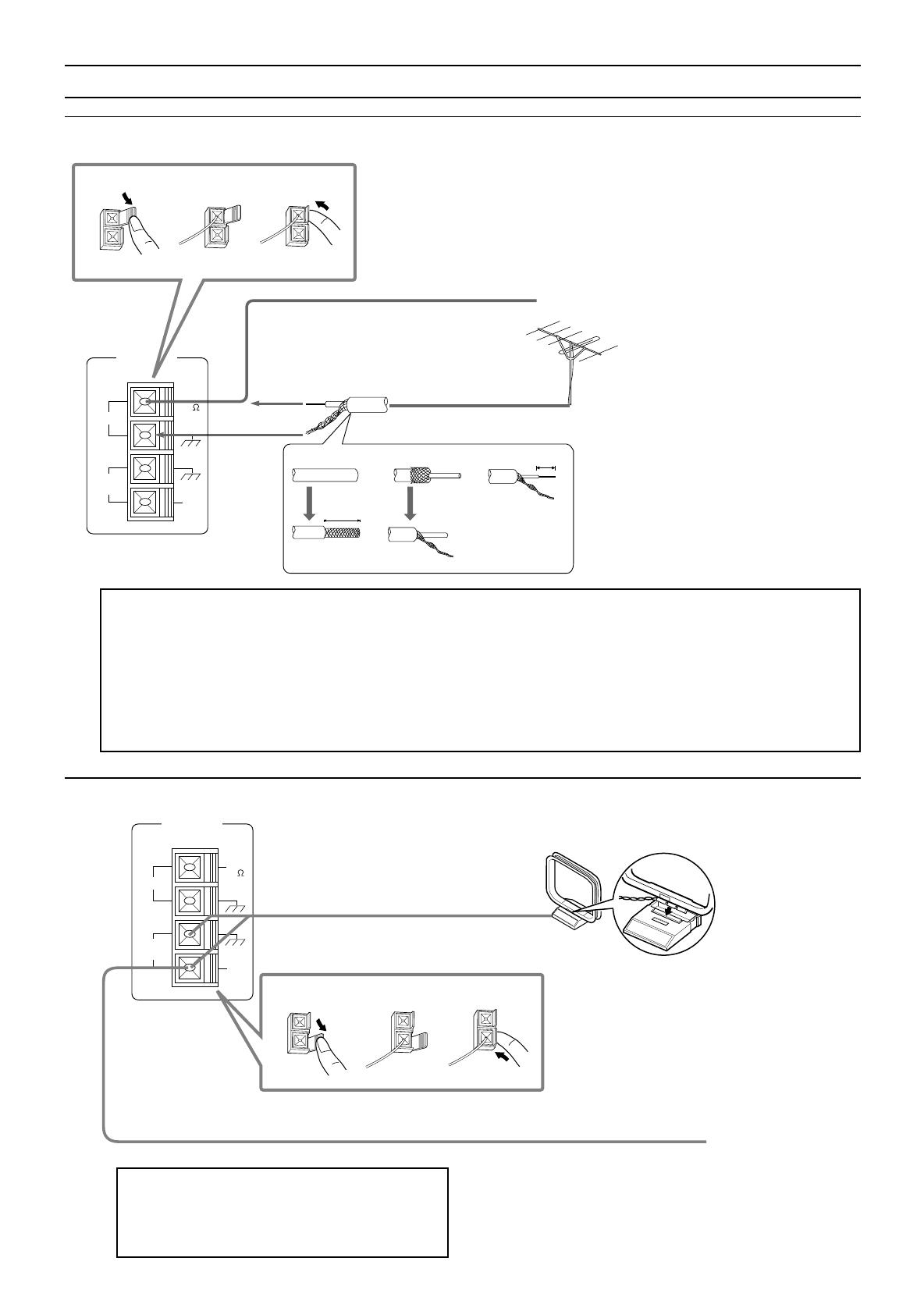
FM Antenna Connections
How to strip the 75-ohm coaxial cable and connect it to the FM terminals
1.
Strip back the outside covering of the 75-ohm coaxial cable to expose the braided metallic mesh about 13/16 inches (20 mm).
2. Pull the mesh back and twist it into a single connector, as shown in the illustration above.
3. Strip the insulation about 7/16 inches (10 mm) back from the central wire.
4. Insert the twisted mesh and the central wire to the FM terminals, as shown in the illustration above.
(10 mm)
7/16 in.
(20 mm)
13/16 in.
1
2
3
4
If reception is poor, connect the outside antenna.
Before attaching a 75-ohm coaxial cable (the kind
with a round wire going to an outside antenna),
disconnect the supplied FM antenna.
Extend the FM wire antenna horizontally.
AM Antenna Connections
Note:
Make sure the antenna conductors do not touch any
other terminals, connecting cords and power cord.
This could cause poor reception.
Snap the tabs on the loop into the slots of
the base to assemble the AM loop.
Turn the loop until you have
the best reception.
AM Loop Antenna
If reception is poor, connect an outdoor single vinyl-covered
wire to the AM EXT terminal. (Keep the AM loop antenna
connected.)
Outdoor Single Vinyl-covered Wire
Outside FM Antenna Wire
FM Antenna
AM
EXT
AM
LOOP
GND
FM
75
FM
GND
ANTENNA
2
3
1
AM
EXT
AM
LOOP
GND
FM
75
FM
GND
2
3
1
ANTENNA
RX-772VBK[J]_0052-001A.En.01-23 97.4.8, 3:23 PM5

Page 6
SPEAKER
IMPEDANCE
/ OHMS
SPEAKER
LOAD
SELECTOR
4 ~ 6
8 ~ 16
LOW
HIGH
+
–
+
–
RIGHT LEFT
1
2
1
2
SPEAKER
LOAD
SELECTOR
FRONT SPEAKERS
LOW
HIGH
RIGHT
1
RIGHT
1
RIGHT
1
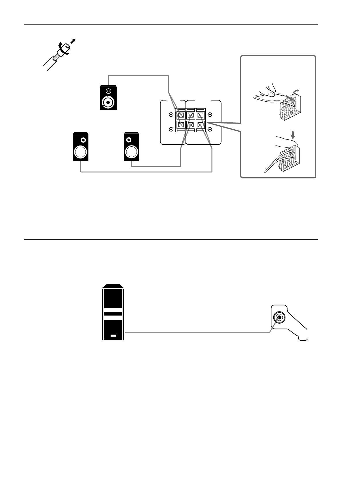
Connecting the Speakers
You can connect the following speakers:
• Two pairs of front speakers to produce normal stereo sound.
• One pair of rear speakers to enjoy the surround effect.
• One center speaker to produce more effective surround effect (to emphasize human voices).
• One subwoofer to enhance the bass.
For each speaker (except for subwoofer), connect the black (–) and red (+) terminals on the rear panel to the
black (–) and red (+) terminals marked on the speakers. For connecting a subwoofer, see page 7.
CAUTION:
Use speakers with the SPEAKER IMPEDANCE indicated by the speaker terminals.
Connecting the front speakers
Cut, twist and remove the insulation at the end of each speaker signal cable first, and then, connect the front
speakers to the FRONT SPEAKERS terminals by using the cables.
You can connect two pairs of front speakers (one pair to the FRONT SPEAKERS 1 terminals, and another
pair to the FRONT SPEAKERS 2 terminals).
Right SpeakerLeft Speaker
1 Turn the knob
counterclockwise.
2 Insert the speaker
signal cable.
3 Turn the knob
clockwise.
Notes:
• To obtain the best possible output power from the receiver, and to prevent the receiver from
being overheated, the receiver has the SPEAKER LOAD SELECTOR which should be set to
match the impedance of the connected speakers.
Set this selector according to the indications by the FRONT SPEAKERS terminals.
• When you connect two pairs of the speakers to the FRONT SPEAKERS terminals, use the
speakers having the impedance within the same range.
RX-772VBK[J]_0052-001A.En.01-23 97.4.8, 3:23 PM6
Page 7
RIGHT LEFT
REAR
SPEAKERS
1
2
CENTER
SPEAKER
Connecting the rear and center speakers
Cut, twist and remove the insulation at the end of each speaker signal cable first, and then, connect rear
speakers to the REAR SPEAKERS terminals and a center speaker to the CENTER SPEAKER terminals by
using the cables.
Notes:
• You can register the center speaker size after you finish its connection. If you register it, you do not have
to set the center speaker mode when setting the surround mode.
(If you do not use a center speaker, register that information.) See page 16.
• When you connect rear speakers, make sure that both left and right speakers are connected; otherwise, no
sound will come out of the rear speakers.
Connecting the subwoofer speaker
You can enhance the bass by connecting a subwoofer.
Connect the input jack of a powered subwoofer to the SUBWOOFER OUT jack on the rear panel, using a cable
with RCA pin plugs.
Open the terminal and
then insert the speaker
signal cable.
Close the terminal.
Center speaker
Right rear speaker
Left rear speaker
Powered subwoofer
SUBWOOFER
OUT
RX-772VBK[J]_0052-001A.En.01-23 97.4.8, 3:23 PM7

Page 8
Connecting Audio/Video Components
You can connect the following audio/video components to this receiver using cables with RCA pin plugs (not
supplied). Refer also to the manuals supplied with your components. If you want to connect a component not
listed in the table below, refer to the manual supplied with it.
Note:
• If you connect a sound-enhancing device such as a graphic equalizer between the source components and
this receiver, the sound output through this receiver may be distorted.
• Any turntables incorporating a small-output cartridge such as an MC (moving-coil type) must be connected
to this receiver through a commercial head amplifier or step-up transformer. Direct connection may result
in insufficient volume.
Audio component connections
Audio Components Video Components
• Turntable • TV
• CD player • VCR
• Cassette deck • Video disc player
If your audio components have a COMPU LINK-3 terminal
The COMPU LINK remote control system allows you to control other JVC audio components from the
receiver or vice versa.
Connect your audio components and the receiver with the cable (monaural mini-plug supplied with those
components) as well as the connection above.
For detailed information about the connection and the COMPU LINK-3 remote control system, see page 35.
Note:
The COMPU LINK-3 remote control system is the upgraded version of the COMPU LINK-1 and COMPU
LINK-2. Even if your component has the COMPU LINK-1 or COMPU LINK-2 jacks, you can still connect
it in the COMPU LINK-3 remote control system, but some functions may not work correctly.
Turntable
To audio output
If an earth cable is provided for your turntable,
connect the cable to the screw marked GND
on the rear panel.
CD player
Cassette deck
To audio output
To audio input
To audio output
GND
RIGHT LEFT
VCR
IN
(PLAY)
OUT
(REC)
CD
PHONO
AUDIO
TAPE
IN
(PLAY)
OUT
(REC)
VCR
OUT
(REC)
IN
(PLAY)
VIDEO
MONITOR
OUT
VIDEO
VIDEO
TV
SOUND
RX-772VBK[J]_0052-001A.En.01-23 97.4.8, 3:23 PM8
Page 9
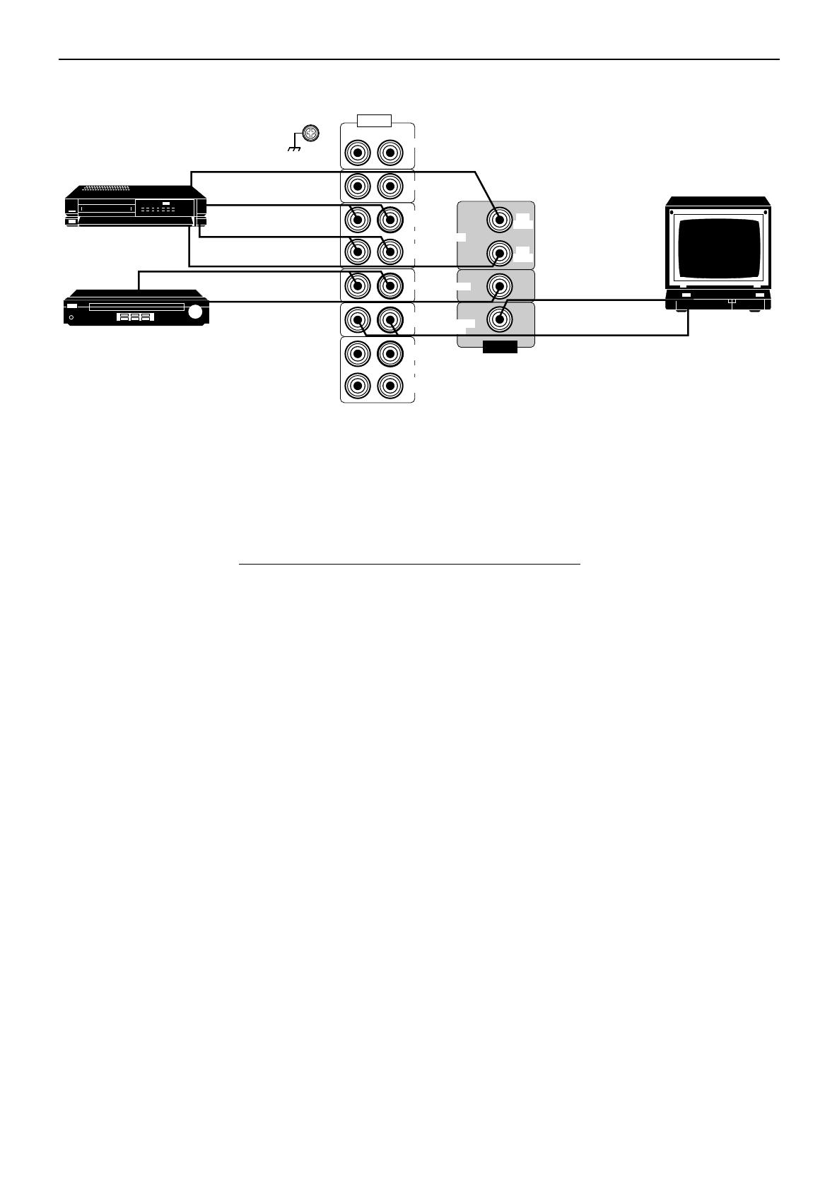
Video component connections
Note:
When connecting a JVC TV:
• If you use the AV COMPU LINK remote control system to operate the TV, connect the receiver to the Video
Input 2 jack on the TV.
• If you do not use the AV COMPU LINK remote control system to operate TV, connect the receiver to the
Video Input 1 jack on the TV.
If your video components have an AV COMPU LINK terminal
The AV COMPU LINK remote control system allows you to control other JVC video components from the
receiver or vice versa.
For detailed information about the connection and the AV COMPU LINK remote control system, see page
36.
Notes:
• The AV COMPU LINK remote control system cannot control the video components connected to the
VIDEO jacks on the receiver, but can control only the VCR connected to the VCR jacks.
• Some VCRs use the AV COMPU LINK jacks for the SWAP editing. However, you cannot use both the AV
COMPU LINK remote control and the SWAP editing at the same time. For the SWAP editing, see the
manual supplied with the VCR.
To audio output
Video disc player
VCR
TV
To audio output
To video output
To audio output
To video input
To video output
To audio input
To video input
(See note below.)
GND
RIGHT LEFT
VCR
IN
(PLAY)
OUT
(REC)
CD
PHONO
AUDIO
TAPE
IN
(PLAY)
OUT
(REC)
VCR
OUT
(REC)
IN
(PLAY)
VIDEO
MONITOR
OUT
VIDEO
VIDEO
TV
SOUND
VHS
RX-772VBK[J]_0052-001A.En.01-23 97.4.8, 3:23 PM9
Page 10
Connecting the Power Cord
Before plugging the receiver into an AC outlet, make sure that all connections have been made.
When the power cord is connected, the STANDBY lamp above the POWER button lights up.
Keep the power cord away from the connecting cables for the TV, VCR, and antenna. The power cord may
cause noise or screen interference. We recommend that you use a coaxial cable to connect the antenna, since
it is well-shielded against interference.
Notes:
• A small amount of power is always consumed even in standby mode. To switch off the power completely,
unplug the power cord from the AC outlet.
• If the power cord is unplugged or a power failure occurs, preset settings will be erased in a few days.
CAUTIONS:
• Do not touch the power cord with wet hands.
• Do not pull on the power cord to unplug the cord. When unplugging the cord, always grasp
the plug so as not to damage the cord.
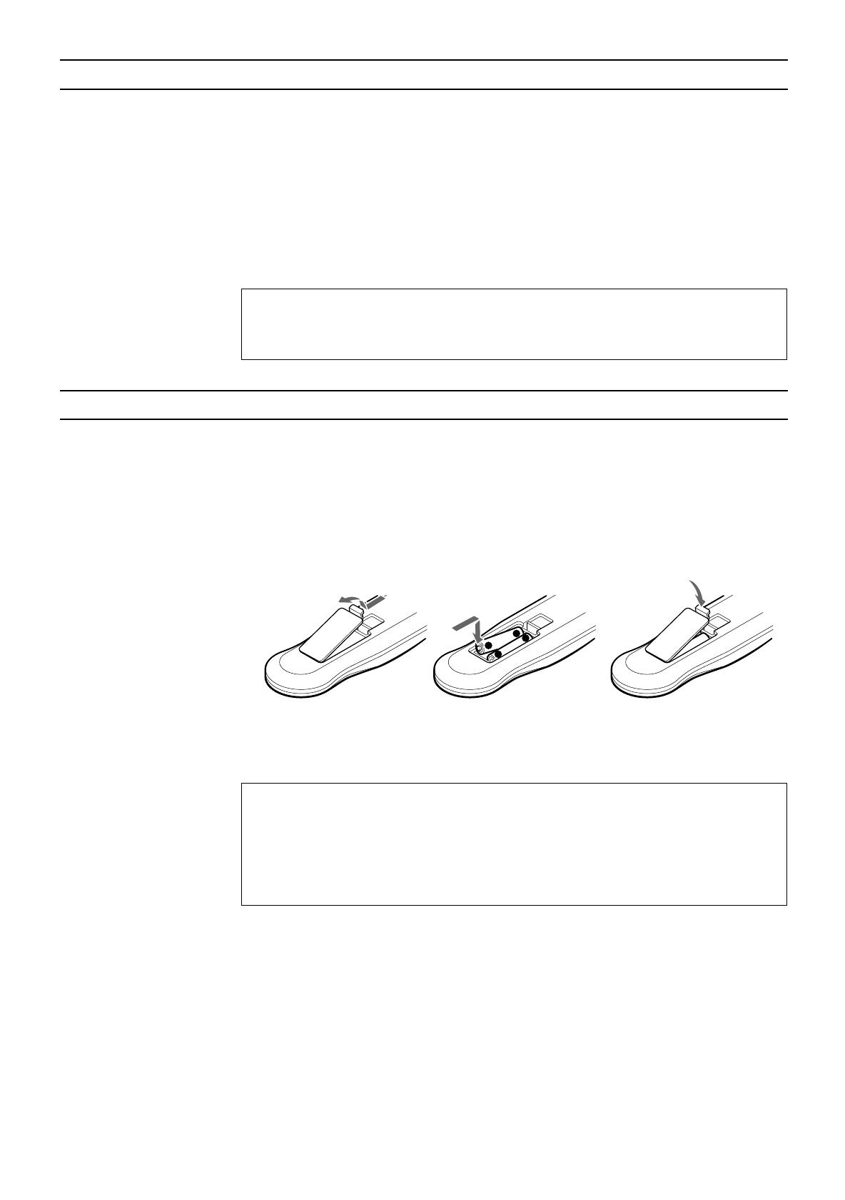
Putting Batteries in the Remote Control
Before using the remote control, put two supplied batteries first. When using the remote control, aim the
remote control directly at the remote sensor on the receiver.
1. On the back of the remote control, remove the cover as illustrated.
2. Insert batteries. Make sure to observe the proper polarity: (+) to (+) and (–) to (–).
3. Replace the cover in.
If the range or effectiveness of the remote control decreases, replace the batteries. Use two R03 (UM-4)/AAA
(24F) type dry-cell batteries.
CAUTIONS:
Follow these precautions to avoid leaking or cracking cells:
• Place batteries in the remote control so they match the polarity indicated: (+) to (+) and (–)
to (–).
• Use the correct type of batteries. Batteries that look similar may differ in voltage.
• Always replace both batteries at the same time.
• Do not expose batteries to heat or flame.
+
-
-
+
R03 (UM-4)/AAA (24F)
RX-772VBK[J]_0052-001A.En.01-23 97.4.8, 3:23 PM10

Page 11
AUDIO/TV
/VCR
CATV
/SAT
STANDBY
POWER
Basic Operations
The following operations are commonly used when you play any sound source.
IMPORTANT
When using the Remote Control, check to see if its remote control mode selector is set to the
correct position:
To operate an audio system, TV, and VCR, set it to the “AUDIO/TV/VCR” position.
To operate a CATV converter and satellite tuner, set it to the “CATV/SAT” position.
Turning the Power On and Off
On the front panel:
To turn on the power, press POWER.
The STANDBY lamp goes off. The name of the current source (or station frequency) appears on the
display.
To turn off the power, press POWER again.
The STANDBY lamp lights up.
From the remote control:
To turn on the power, press AUDIO POWER.
The STANDBY lamp goes off. The name of the current source appears on the display.
To turn off the power, press AUDIO POWER again.
The STANDBY lamp lights up.
Selecting the Source to Play
You need to select the source before you start playing any source.
On the front panel:
1. Press SOURCE so that the Control
%%
%%
% /
fifi
fifi
fi buttons work for selecting the source.
2. Press Control
%%
%%
% /
fifi
fifi
fi until the source name you want appears on the display.
The selected source lamp also lights up.
Front panel
STANDBY
POWER
Current source
name appears
Volume level is also
shown here
whenever the power
is on.
AUDIO
POWER
VOLUME
100 1k 10k
Remote Control
SOURCE
Front panel
MENU
See also
page 31.
Selected source
name appears
MUTE AUTO TUNED STEREO
SURROUND PRO LOGIC LOGIC3CH HALL
SEA
LOUDNESS
VOLUMEVISUAL CONFIRMATION
CH–
MHz
kHz
FM
AM
SLEEP
100 1k 10k
RX-772VBK[J]_0052-001A.En.01-23 97.4.8, 3:23 PM11
Page 12
From the remote control:
Press one of the source selecting buttons you want.
VIDEO Play back a video source on the video component connected to the VIDEO jacks.
VCR Play back a video source on the video component connected to the VCR jacks.
TV SOUND Listen to TV sounds.
FM/AM* Listen to the radio.
Each time you press the button, the band alternates between FM and AM.
TAPE* Listen to a cassette tape connected to the TAPE jacks.
CD* Listen to a CD.
PHONO* Listen to a record.
Note:
When you press one of the source selecting buttons marked above with an asterisk (*), the receiver
automatically turns on.
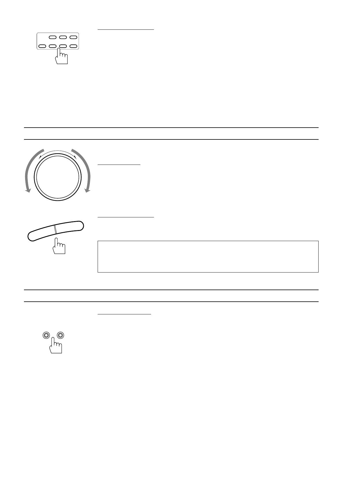
Adjusting the Volume
When you change the volume level, the volume level is shown on the display.
On the front panel:
To increase the volume, turn MASTER VOLUME clockwise.
To decrease the volume, turn MASTER VOLUME counterclockwise.
Note:
When you turn MASTER VOLUME rapidly, the volume level also changes rapidly.
When you turn MASTER VOLUME slowly, the volume level also changes slowly.
From the remote control:
To increase the volume, press VOLUME +.
To decrease the volume, press VOLUME –.
CAUTION:
Always set the volume level to the minimum before starting any source. If the volume level is
left turned up, the sudden blast of sound energy can permanently damage your hearing and/
or ruin your speakers.
Selecting the Front Speakers
On the front panel only:
When you have connected two pairs of the front speakers, you can select which to use. Pressing SPEAKERS
1 or SPEAKERS 2 to set it in the _ON position activates the respective pair of the speakers.
To use the speakers connected to the FRONT SPEAKERS 1 terminals, press SPEAKERS 1 to set it in
the _ON position, and press SPEAKERS 2 to set it in the —OFF position.
To use the speakers connected to the FRONT SPEAKERS 2 terminals, press SPEAKERS 2 to set it in
the _ON position, and press SPEAKERS 1 to set it in the —OFF position.
To use both pairs of the speakers, press both SPEAKERS 1 and 2 to set them in the _ON position.
To use neither pair of the speakers, press both SPEAKERS 1 and 2 to set them in the —OFF position.
Note:
When only one set of the speakers is connected to either the FRONT SPEAKERS
1
or
2
terminals, do not
press both SPEAKERS 1 and 2 to set them in the
_
ON position. If you do, no sound comes out of the front
speakers.
VIDEO TAPEVCR
TV
SOUND FM/AM PHONOCD
Remote Control
SPEAKERS
12
_ON —OFF
Front panel
MASTER VOLUME
–
+
Front panel
Remote Control
–
+
VOLUME
RX-772VBK[J]_0052-001A.En.01-23 97.4.8, 3:24 PM12

Page 13
Listening with Headphones
A standard pair of headphones can be connected to the PHONES jack on the front panel.
To listen with only headphones, press both SPEAKERS 1 and 2 to set them in the —OFF position.
No sound comes out of the front speakers.
CAUTION:
Be sure to turn down the volume before connecting or putting on headphones, as high volume
can damage both the headphones and your hearing.
Muting the Sound
From the remote control only:
To mute the sound through all the speakers and headphones connected, press MUTE so that
“MUTE” appears on the display and the volume turns off.
To cancel the mute, press MUTE again so that “OFF” appears on the display.
Turning MASTER VOLUME or pressing VOLUME +/– also restores the sound at the previous volume level.
Recording a Source
You can record any source playing through the receiver to the cassette deck connected to the TAPE jacks and
the VCR connected to the VCR jacks at the same time.
While recording, you can listen to the selected sound source at whatever sound level you like, without affecting
the sound levels of the recording.
Note:
The output volume level, SEA and surround adjustments cannot affect the recording.
Remote Control
MUTE
RX-772VBK[J]_0052-001A.En.01-23 97.4.8, 3:24 PM13
Page 14
SETTING
Front panel
Basic Settings
Some of the following settings are required after connecting and positioning your speakers in your listening
room, while others will make operations easier.
Adjusting the Front Speaker Output Balance
If the sounds you hear from the front right and left speakers are unequal, you can adjust the speaker output
balance.
On the front panel only:
1. Press SETTING so that the Control
%%
%%
% /
fifi
fifi
fi /
@@
@@
@ /
##
##
# buttons work for adjusting the balance.
The lamp next to the button lights up.
2. Press Control
%%
%%
% /
fifi
fifi
fi until “BALANCE” appears on the display.
3. Press Control
@@
@@
@ /
##
##
# to adjust the balance.
• Pressing Control @ decreases the right channel output.
• Pressing Control # decreases the left channel output.
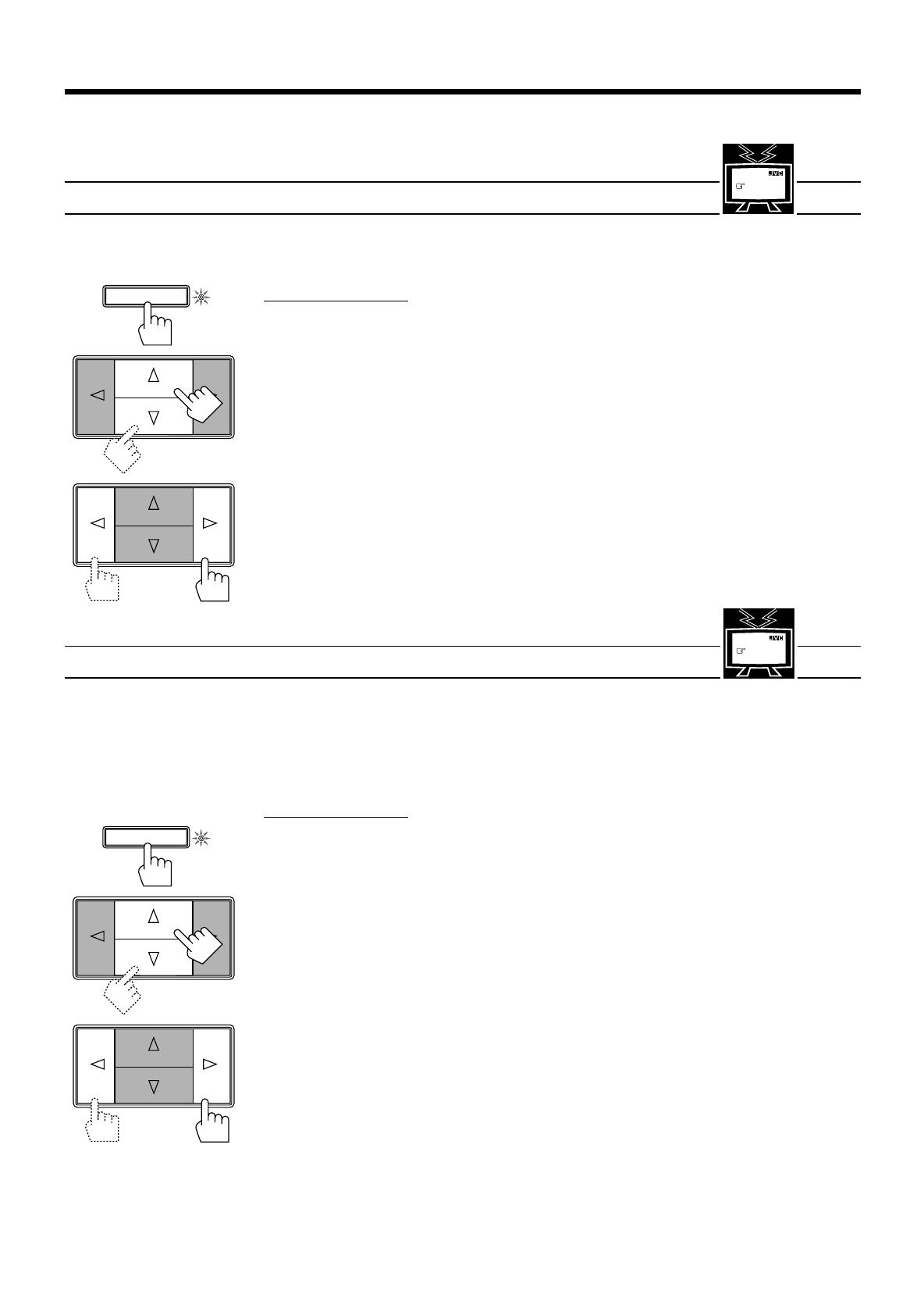
Listening at Low Volume (Loudness)
Human ears are not sensitive to bass at low volume. To compensate for this, the loudness function
automatically boosts the bass level as you lower the volume.
Note:
The loudness function affects the front speaker sounds only.
On the front panel only:
1. Press SETTING so that the Control
%%
%%
% /
fifi
fifi
fi /
@@
@@
@ /
##
##
# buttons work for setting the loudness
function.
The lamp next to the button lights up.
2. Press Control
%%
%%
% /
fifi
fifi
fi until “LOUDNESS” appears on the display.
3. Press Control
@@
@@
@ /
##
##
# to set the loudness function to “ON” or “OFF.”
• Select “ON ” to activate the loudness function.
The LOUDNESS indicator lights up on the display.
• Select “OFF” to cancel it.
The indicator goes off.
MENU
See also
page 31.
MENU
See also
page 32.
SETTING
Front panel
RX-772VBK[J]_0052-001A.En.01-23 97.4.8, 3:24 PM14

Page 15
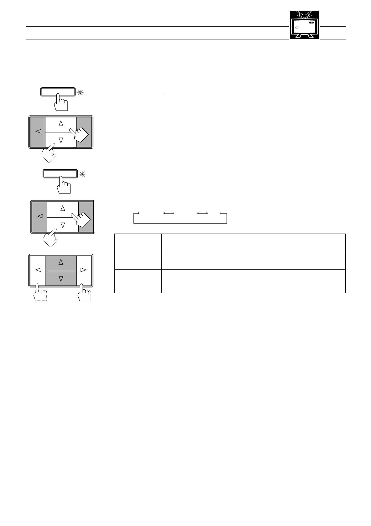
Using the Sleep Timer
Using the Sleep Timer, you can fall asleep to music and know the receiver will turn off by itself rather than
play all night.
On the front panel:
1. Press SETTING so that the Control
%%
%%
% /
fifi
fifi
fi /
@@
@@
@ /
##
##
# buttons work for setting the Sleep Timer
The lamp next to the button lights up.
2. Press Control
%%
%%
% /
fifi
fifi
fi until “<SLEEP>” appears on the display.
3. Press Control
@@
@@
@ /
##
##
# to set the shut-off time.
Each time you press the button, the shut-off time on the display changes as follows:
The SLEEP indicator lights up on the display.
When the shut-off time comes
The receiver turns off automatically.
To check or change the time remaining until the shut-off time
1. Press SETTING, if necessary, so that the Control % / fi / @ / # buttons work for setting the Sleep
Timer.
2. Press Control % / fi, if necessary, until “<SLEEP>” appears on the display.
3. Press Control @ / # once.
The remaining time until the shut-off time appears in minutes.
• To change the shut-off time, press Control @ / # repeatedly.
To cancel the Sleep Timer
Press Control @ / # repeatedly in step 3 above until “0” appears on the display. (The SLEEP indicator goes
off.) Turning off the power also cancels the Sleep Timer.
From the remote control:
Press SLEEP repeatedly.
The SLEEP indicator lights up and the shut-off time appears on the display.
Each time you press the button, the shut-off time on the display changes as follows:
To check or change the time remaining until the shut-off time
Press SLEEP once. The remaining time until the shut-off time appears in minutes.
• To change the shut-off time, press SLEEP repeatedly.
To cancel the Sleep Timer
Press SLEEP repeatedly until “0” appears on the display. (The SLEEP indicator goes off.)
Turning off the power also cancels the Sleep Timer.
MENU
See also
page 32.
2010 30 40 50 60 70 80
(Canceled)
0
Remote Control
SLEEP
SETTING
Front panel
2010 30 40 50 60 70 80
(Canceled)
0
RX-772VBK[J]_0052-001A.En.01-23 97.4.8, 3:24 PM15
Page 16
Selecting the Center Speaker Size
You can register the information on the center speaker after all connections are completed.
If you do this registration first, you do not have to adjust the center speaker mode when you want to activate
the Dolby surround. However, to register the information, first you have to set the surround mode either to
“PROLOGIC” or “3CHLOGIC.” (You cannot select the center speaker size when the surround mode is
“SURR OFF” or “HALL.”)
On the front panel only:
1. Press SURROUND MODE so that the Control
%%
%%
% /
fifi
fifi
fi buttons work for selecting the surround
mode.
The lamp next to the button lights up.
2. Press Control
%%
%%
% /
fifi
fifi
fi until “PROLOGIC” or “3CHLOGIC” whichever you want appears on the
display.
The PRO LOGIC or 3CH LOGIC indicator (as well as the SURROUND indicator) also lights up.
3. Press SETTING so that the Control
%%
%%
% /
fifi
fifi
fi /
@@
@@
@ /
##
##
# buttons work for selecting the center speaker
size.
The lamp next to the button lights up.
4. Press Control
%%
%%
% /
fifi
fifi
fi until “CNTR SPK” (Center Speaker) appears on the display.
5. Press Control
@@
@@
@ /
##
##
# to select the appropriate item about your center speaker.
Each time you press the button, the display changes to show the following:
LARGE: Select this mode when the size of the center speaker is the same as that of the
front speakers.
SMALL: Select this mode when the size of the center speaker is smaller than that of the
front speakers.
NO: Select this mode when you do not use a center speaker.
(You cannot select this mode when “3CHLOGIC” is selected for the surround
mode.)
Note:
This center speaker size setting is so related to the center mode setting for the surround mode that changing
this setting affects and changes the center mode to a relevant mode, and vice versa.
For example;
• If you select “LARGE,” the center mode is automatically set to “WIDE,” and vice versa.
• If you select “SMALL,” the center mode is automatically set to “NORMAL,” and vice versa.
• If you select “NO,” the center mode is automatically set to “PHANTOM” for Pro Logic, and vice versa.
MENU
See also
page 32.
SETTING
SURROUND MODE
Front panel
LARGE SMALL NO
RX-772VBK[J]_0052-001A.En.01-23 97.4.8, 3:24 PM16

Page 17
Using Visual Confirmation
When you operate the receiver, you can see what you are doing, by showing it on the TV screen.
To use this function, you need to connect the TV to the MONITOR OUT jack on the rear panel (see page 9),
and set the TV’s input mode to the proper position to which the receiver is connected.
When the TV’s input mode is for TV, you cannot see the on-screen display.
On the front panel only:
1. Press SETTING so that the Control
%%
%%
% /
fifi
fifi
fi /
@@
@@
@ /
##
##
# buttons work for setting Visual
Confirmation.
The lamp next to the button lights up.
2. Press Control
%%
%%
% /
fifi
fifi
fi until “VCONFIRM” appears on the display.
3. Press Control
@@
@@
@ /
##
##
# to set Visual Confirmation to “ON” or “OFF.”
• Select “ON ” to activate Visual Confirmation.
The VISUAL CONFIRMATION indicator lights up on the display.
• Select “OFF” to cancel it.
The indicator goes off.
EXAMPLES:
When changing the source:
When adjusting the front speaker output balance:
When selecting your favorite SEA mode:
MENU
See also
page 32.
The SOURCE menu appears on the TV screen for
about 5 seconds.
SETTING
Front panel
The SETTING menu appears on the TV screen for
about 5 seconds.
The SEA MODE menu appears on the TV screen for
about 5 seconds.
RX-772VBK[J]_0052-001A.En.01-23 97.4.8, 3:24 PM17
/