Page is loading ...

Installation instructions
Integrated dishwasher
To prevent accidents and
machine damage,
read these
instructions before
installation or use.
UV
05 620 661
M.-Nr.

IMPORTANT SAFETY INSTRUCTIONS. . . . . . . . . . . . . . . . . . . . . . . . . . . . . . . . . 3
INSTRUCTIONS IMPORTANTES SUR LA SÉCURITÉ . . . . . . . . . . . . . . . . . . . . . 5
Caring for the environment . . . . . . . . . . . . . . . . . . . . . . . . . . . . . . . . . . . . . . . . . . 7
Disposal of the packing material . . . . . . . . . . . . . . . . . . . . . . . . . . . . . . . . . . . . . . . 7
Disposal of an old machine . . . . . . . . . . . . . . . . . . . . . . . . . . . . . . . . . . . . . . . . . . . 7
Opening the door . . . . . . . . . . . . . . . . . . . . . . . . . . . . . . . . . . . . . . . . . . . . . . . . . . 8
Opening the door without a panel in place . . . . . . . . . . . . . . . . . . . . . . . . . . . . . . . 8
Without the mounting bracket in place: . . . . . . . . . . . . . . . . . . . . . . . . . . . . . . . 8
Product and Cut-out Dimensions. . . . . . . . . . . . . . . . . . . . . . . . . . . . . . . . . . . . . 9
Installation . . . . . . . . . . . . . . . . . . . . . . . . . . . . . . . . . . . . . . . . . . . . . . . . . . . . . . 11
1. Install the steam deflector. . . . . . . . . . . . . . . . . . . . . . . . . . . . . . . . . . . . . . . . . 11
2. Install the mounting brackets . . . . . . . . . . . . . . . . . . . . . . . . . . . . . . . . . . . . . . 13
3. Install the slide skis. . . . . . . . . . . . . . . . . . . . . . . . . . . . . . . . . . . . . . . . . . . . . . 13
4. Install the dishwasher under the countertop . . . . . . . . . . . . . . . . . . . . . . . . . . 14
5. Level the legs . . . . . . . . . . . . . . . . . . . . . . . . . . . . . . . . . . . . . . . . . . . . . . . . . . 15
6. Install the custom door panel . . . . . . . . . . . . . . . . . . . . . . . . . . . . . . . . . . . . . . 16
7. Adjust and secure the front panel. . . . . . . . . . . . . . . . . . . . . . . . . . . . . . . . . . . 21
8. Secure the dishwasher . . . . . . . . . . . . . . . . . . . . . . . . . . . . . . . . . . . . . . . . . . . 22
9. Adjust the door springs . . . . . . . . . . . . . . . . . . . . . . . . . . . . . . . . . . . . . . . . . . 24
10. Make the plumbing connections . . . . . . . . . . . . . . . . . . . . . . . . . . . . . . . . . . . 25
11. Make the electrical connection . . . . . . . . . . . . . . . . . . . . . . . . . . . . . . . . . . . . 29
12. Test the unit . . . . . . . . . . . . . . . . . . . . . . . . . . . . . . . . . . . . . . . . . . . . . . . . . . . 31
13. Install the toekick . . . . . . . . . . . . . . . . . . . . . . . . . . . . . . . . . . . . . . . . . . . . . . . 32
Contents
2

Installation
Installation, maintenance and re
-
pair work should be by a Miele
authorized service technician. Work by
unqualified persons could be a hazard
and may void the warranty.
This equipment is not designed for
maritime use or for use in mobile
installations such as caravans or air
-
craft. However, under certain conditions
it may be possible for an installation in
these applications. Please contact the
nearest Miele dealer or the Miele Tech
-
nical Service Department with specific
requirements.
Inspect the dishwasher for trans-
port damage. Do not install or use
a damaged unit. Contact the place of
purchase.
This dishwasher must be installed
under a continuous countertop
secured to adjacent cabinetry.
Do not install this dishwasher be-
neath a cooking surface or oven.
Do not, under any circumstances,
cut the intake hose or submerge in
liquid. This hose contains electrical
components that could cause injury or
property damage if cut or submerged.
If there is any doubt concerning in
-
stallation contact the Technical Ser
-
vice Department.
USA 1-800-999-1360
CDN 1-800-565-6435
,
During the installation process,
please be careful of sharp edges
that can cause harm.
IMPORTANT SAFETY INSTRUCTIONS
3

Electrical safety
Before installation, make sure the
voltage and frequency listed on the
data plate correspond with the house
-
hold electrical supply. This data must
correspond to prevent injury and
machine damage. Consult a qualified
electrician if in doubt.
To guarantee the electrical safety
of this appliance, continuity must
exist between the appliance and an
effective grounding system.
It is imperative that this basic safety
requirement be met. If there is any
doubt, have the electrical system of the
house checked by a qualified electri-
cian. The manufacturer cannot be held
responsible for damages caused by the
lack, or inadequacy of, an effective
grounding system
Before installation or service,
disconnect the power supply to the
work area by manually "tripping" the
circuit breaker, unplugging the unit, or
removing the fuse.
Do not use an extension cord to
connect the unit to electricity. Ex
-
tension cords do not guarantee the re
-
quired safety of the appliance, (e.g.
danger of overheating).
Child safety
Ensure that any plastic wrappings,
bags etc. are disposed of safely
and kept out of the reach of babies and
young children. Danger of suffocation!
If the appliance is removed from its
installation and will not be used,
the door to the wash cabinet should be
removed to prevent children from being
locked in the machine.
When discarding an old dish-
washer, unplug it from the power
outlet, remove the door to the wash
cabinet and cut off the power cord.
IMPORTANT SAFETY INSTRUCTIONS
4

Installation
L’installation et les travaux de répa
-
ration et d’entretien doivent être ef
-
fectués par un technicien de service
autorisé Miele. Les travaux effectués
par des personnes non qualifiées,
pourraient être dangereux et faire annu
-
ler la garantie.
Cet équipement n’a pas été conçu
pour usage maritime ou pour les
installations mobiles telles que les rou
-
lottes ou les avions. Toutefois, il peut
être parfois possible de faire l’installa
-
tion de ces applications sous certaines
conditions. Veuillez contacter le Con-
cessionnaire Miele le plus près de
chez-vous ou le Département du servi-
ce technique Miele pour leur donner
vos exigences précises.
Inspecter le lave-vaisselle pour voir
s’il a été endommagé lors de l’ex-
pédition. Ne pas installer ou utiliser, un
appareil endommagé. Veuillez contac-
ter le point d’achat.
Ce lave-vaisselle doit être installé
sous un comptoir continu bien fixé
aux armoires adjacentes.
Ne pas installer ce lave-vaisselle
sous une surface de cuisson ou un
four.
Ne jamais, sous aucunes circons
-
tances, couper le boyau de prise
ou submerger dans un liquide. Ce
boyau contient des éléments électri
-
ques qui pourraient causer des blessu
-
res ou des dégâts matériels s’ils sont
coupés ou submergés.
Si vous avez des doutes au sujet
de l’installation, contactez le Dé
-
partement du service technique Miele.
USA 1-800-999-1360
CDN 1-800-565-6435
,
Durant le processus
d’installation, veuillez faire attention
aux rebords coupants qui peuvent
blesser.
INSTRUCTIONS IMPORTANTES SUR LA SÉCURITÉ
5

Sécurité électrique
Avant l’installation, s’assurer que la
tension et la fréquence énumérées
sur la plaque signalétique correspon
-
dent à la source d’électricité de la rési
-
dence. Ces données doivent corres
-
pondre afin d’éviter de vous blesser et
d’endommager l’appareil. Consulter un
électricien qualifié si vous avez des
doutes.
Pour garantir la sécurité électrique
de cet appareil, il doit y avoir conti
-
nuité entre l’appareil et un système effi
-
cace de mise à la terre. Ce critère de
sécurité doit absolument être respecté.
Si vous avez des doutes, faire vérifier le
système électrique de votre maison par
un électricien qualifié. Le fabricant ne
peut pas être tenu responsable des
dommages causés par un système de
mise à la terre efficace, manquant ou
inadéquat.
Débrancher le courant de la zone
de travail avant l’installation, en dé-
branchant l’appareil, retirant le fusible
ou en faisant "sauter" le disjoncteur.
Ne pas utiliser de rallonge pour
brancher l’appareil. Les rallonges
ne garantissent pas la sécurité requise
pour l’appareil, (par ex. danger de sur
-
chauffage).
Sécurité des enfants
S’assurer de disposer de tous les
emballages de plastique, sacs etc.
et de les garder hors de la porté des
bébés et jeunes enfants. Danger de
suffocation!
Si l’appareil est retiré de son instal
-
lation et que vous ne l’utilisez pas,
vous devez retirer la porte du meuble
de lavage pour empêcher les enfants
de s’enfermer dans l’appareil.
Pour disposer d’un ancien
lave-vaisselle, le débrancher de la
prise, enlever la porte du meuble de la-
vage et couper le cordon électrique.
INSTRUCTIONS IMPORTANTES SUR LA SÉCURITÉ
6

Disposal of the packing
material
The cardboard box and packaging
protect the appliance during shipping.
These materials are biodegradable and
recyclable. Please recycle.
Ensure that any plastic wrappings,
bags etc. are disposed of safely and
kept out of the reach of children.
Danger of suffocation!
Disposal of an old machine
Old appliances may contain materials
that can be recycled. Please contact
your local recycling authority about the
possibilty of recycling these materials.
Ensure that the appliance presents no
danger to children while being stored
for disposal. Before discarding an old
appliance, unplug it from the outlet and
cut off its power cord and remove any
doors to prevent hazards
Caring for the environment
7

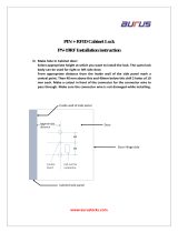
Opening the door without a
panel in place
^ Gently pull on the upper portion of
the mounting bracket until the door
latch releases (small arrow).
Without the mounting bracket in
place:
^ Grip the T shaped opening with a fin-
ger and pull the door open.
Opening the door
8

G 600 Series Dishwashers
Full size models G 643 - G 663
Removing the leg extensions
The black leg extensions can be re
-
moved to reduce the machine height to
32
1
/
4
" - 33" (819-838 mm) (see Inset).
A = Black leg extension (removable)
B = White leg (must be installed on
machine).
^ After removing the black leg exten-
sions, screw the white legs onto the
dishwasher.
Machine heights of 33
1
/
4
" - 34"
(845-864 mm) are not possible using
the supplied legs.
For this height range, or for heights
greater than 34
7
/
8
" (886 mm), ex
-
tended legs (part # 02 702 601) are
necessary.
Contact the Miele Technical Service
Department for the appropriate legs.
Product and Cut-out Dimensions
9

G 800 Series Dishwashers
Full size models G 843 - G 863
Machine heights of 35" - 37"
(889-940 mm) cannot be obtained
using the supplied legs.
For this height range, or for heights
greater than 35" (889 mm), extended
legs (part# 02 702 601) are neces-
sary.
Contact the Miele Technical Service
Department for the appropriate legs.
Product and Cut-out Dimensions
10

1.Install the steam deflector
A stainless steel steam deflector is sup
-
plied to protect the countertop from
steam and condesation when the dish
-
washer is opened. If the countertop is
made of Corian®, granite, marble or
other solid, waterproof material, the
steam deflector is not required.
The steam deflector has an indicator re
-
flector to show when the dishwasher is
running.
The left side of the reflector and the
optic indicator in the the control
panel must line up for the reflector to
work.
If the counter is made of different
materials, the steam deflector
should be positioned so it covers the
edge where the materials are joined.
Countertops with wood or laminate
edging should be tacked through
the rear holes of the steam deflector.
^
Squeeze a bead of silicone sealant
from the supplied tube into the ridge
formed by the curved edge, a, of the
steam deflector.
^ Line up the steam deflector, b, with
the lower front edge of the countertop
and use the supplied tacks to nail in
place.
^ Wipe off any excess silicone with a
rag.
^
Press the optic indicator reflector in
place.
Installation
11

Stone or marble countertops:
The steam deflector is not required for
countertops made of solid, waterproof
material. But it is needed for determin
-
ing the correct position of the optic
indicator reflector.
^
Remove the black plastic reflector
holder from the steam deflector.
^ With the reflector cut out left and
frontward, align the steam deflector
with the front edge of the counter.
Trace the outline of the reflector onto
the underside of the counter with a
pencil.
Note:
For rounded countertops, make the
tracing closer to the counter’s edge so
the optic reflection will be visible.
^
Adhere the double-sided sticker to
the back of the optic indicator
reflector.
^
Remove the backing from the other
side of the sticker.
^ Line up the reflector with the tracing
and press into place.
The "Extended drying" feature can
be activated to further protect the
counter from condensation. See the
"Operating instructions / Additional
features".
Installation
12

2. Install the mounting
brackets
To ensure stability this dishwasher
should be securely attached to the
countertop with the two mounting
brackets included.
^ Insert the tab of each bracket into the
guide holes on top.
Stone or marble counterops:
Do not install these mounting brackets
if the counter is made of an extremely
hard material. The securing screws for
the mounting brackets are not suitable
for such materials.
3. Install the slide skis
Two slide skis are included and should
be installed on the feet of the dish
-
washer before the machine is pushed
under the countertop. This will allow the
machine to slide easier, protect the
floor, and allow adjustment of the rear
leveling legs from the front of the unit.
^
First, adjust the height of the legs so
that the top of the dishwasher is
roughly
1
/
8
" (3 mm) below the
countertop.
Tipping the machine slightly to the rear,
if possible, will make adjusting the front
legs easier. Make sure the machine is
level when adjustments are complete.
^
Place the skis, with the ratchet at the
rear, under the dishwasher legs.
Installation
13

4.Install the dishwasher
under the countertop
The dishwasher must be installed so
that the water and electricity supplies
can be accessed through an adjacent
cabinet. The supplies must not be lo
-
cated behind the machine.
The floor of the cut out where the dish
-
washer will be installed should be even
in height with the surrounding kitchen
floor. Plywood can be secured to the
floor to make the two areas even.
^
Make a 2" x 4" (5 x 10 cm) cut out in
the side or bottom of the cabinet ad
-
joining the dishwasher. This cut out is
necessary for connections to pass
through.
^
Make certain that there are no rough
edges that could damage the power
cord or hoses. If metal cabinets are
used, place the supplied rubber
grommet around the edge of the ope
-
ning before passing the cable
through.
^
Slide the machine into the opening,
making sure the electrical cable and
hoses can reach their connection
points without kinking.
The left side of the optic indicator
reflector and the optic indicator must
align.
The drain hose connection at the rear of
the dishwasher can be turned to allow
the hose to be angled to the right or
left.
^
Exercise care when sliding the dish
-
washer in or out, to prevent damag
-
ing the power cord or hoses.
Installation
14

5. Level the legs
^ The rear leveling legs can be ad-
justed with a T20 Torx screwdriver by
turning the screws at the front of the
slide skis.
To raise the machine turn clockwise.
To lower the machine turn counter
clockwise.
Several turns may be needed to set the
correct height. Do not use a power
screwdriver.
^ Adjust the front leveling legs by
pushing on the feet with a slotted
screwdriver.
^ Tipping the machine slightly back-
wards, if posssible will make adjust-
ing the front legs easier. Make sure
the machine is level when adjust-
ments are complete.
The dishwasher should be raised
until it just touches the underside of
the countertop.
Installation
15

6.Install the custom door
panel
A custom door panel must be installed
on the dishwasher before it can be
safely operated. A single large panel or
a two piece panel separated at the
drawer line can be used.
Panel size is determined in the follow
-
ing manner:
Panel Height = HTC - TKH
HTC = Height to the underside of
countertop
TKH = Toe Kick Height
Panel Dimensions:
Width:
. . . . . . . . . . . . . . . 23
1
/
2
" (60 cm)
Range of panel height:
G 800 series. . . . . . . . . . 27
1
/
2
" - 30
1
/
4
"
. . . . . . . . . . . . . . . . . . . (699 - 768 mm)
G 600 series. . . . . . . . . . 25
1
/
2
" - 28
1
/
4
"
. . . . . . . . . . . . . . . . . . . (648 - 718 mm)
Thickness:
At least
3
/
4
" (18 mm) where the mount
-
ing bracket is to be screwed in position.
Maximum panel weight:
G 800 series . . . . . . . . . . 12 lbs (5.5 kg)
G 600 series . . . . . . . . . . 13 lbs (5.9 kg)
Installation
16

The door panel is attached to the dish
-
washer using the mounting bracket that
comes secured to the front of the unit.
To remove the bracket:
^ Open the door 2 - 4" (5 - 10 cm).
^ Loosen the bracket retaining screw
(black arrow) located on each side of
the machine door.
^ Pull the bracket up until the upper
section of the bracket disengages
from the locator pins, then remove
the bracket.
Installation
17

Install the bracket on the rear of the
custom door panel
^
Make sure the dishwasher is level.
^
Measure the distance X between the
round hole in the machine outer door
panel (shown in inset) and the lower
edge of the adjoining cabinet door.
^ Place the door panel on a flat sur-
face, good side face down, being
careful not to scratch the surface.
Make certain that the bottom of the
panel is towards you.
^
Using a pencil, lightly draw a vertical
centerline on the panel (See illustra
-
tion on the next page).
^
Draw a horizontal line X inches up
from the bottom edge of the panel.
For two piece panels:
Two piece panels should be made so
that any joining hardware is flush with
the back of the panel. Failure to do this
may impede proper operation of the
dishwasher.
In certain instances, you may be able
to use the mounting bracket supplied
with the machine to secure both pieces
to the dishwasher.
Consult your cabinet supplier / maker
for the best method of joining the pan-
els.
When mounting the two pieces,
make sure that the desired finished
panel height is maintained.
Installation
18

^
Place the bracket on the door panel
so the notches, a, cross the previ
-
ously drawn centerline, and the bot
-
tom of the bracket lines up with the
horizontal X line.
^
Mark and drill pilot holes for the
screws using a
3
/
32
" (2.5 mm) drill bit.
^
Attach the bracket to the back of the
panel, using the 14 screws provided.
The top four pair of holes, only need
to be secured once per pair.
^
Double check the location of the
bracket before mounting the panel to
the dishwasher.
The door handle must be installed on
the panel before it is attached to the
machine. It should be located in the
center of the panel at a height that will
match the surrounding drawer handles.
Any screws used to attach the door
handle must be countersunk so that
the rear of the front panel remains
flat.
Installation
19

Attach the front panel to the
dishwasher
^
Open the door 2 - 4" (5 - 10 cm).
^ Place the lower mounting clips into
the slots of the dishwasher door as
shown in the illustration.
^
Seat the U shaped slots of the upper
bracket onto their respective locator
pins.
^
Press the panel against the door and
slide down so that all the brackets
catch.
The "T" shaped hanger behind the door
handle should fit easily into its respec-
tive hole.
Installation
20
/