Page is loading ...

Instruction Manual
Bedienungsanleitung
Manuel d’utilisation
Manuale di Istruzioni
®
NX8
8-Channel 2.4GHz
DSMX
®
Aircraft System

2 SPEKTRUM NX8 • TRANSMITTER INSTRUCTION MANUAL
EN
WARNING: Read the ENTIRE instruction manual to become familiar with the features of the product before operating.
Failure to operate the product correctly can result in damage to the product, personal property and cause serious injury.
This is a sophisticated hobby product. It must be operated with caution and common sense and requires some basic mechanical
ability. Failure to operate this Product in a safe and responsible manner could result in injury or damage to the product or other
property. This product is not intended for use by children without direct adult supervision. Do not attempt disassembly, use with
incompatible components or augment product in any way without the approval of Horizon Hobby, LLC. This manual contains
instructions for safety, operation and maintenance. It is essential to read and follow all the instructions and warnings in the manual,
prior to assembly, setup or use, in order to operate correctly and avoid damage or serious injury.
WARNING AGAINST COUNTERFEIT PRODUCTS: Always purchase from a Horizon Hobby, LLC authorized dealer to ensure
authentic high-quality Spektrum product. Horizon Hobby, LLC disclaims all support and warranty with regards, but not limited
to, compatibility and perform ance of counterfeit products or products claiming compatibility with DSM or Spektrum technology.
NOTICE: This product is only intended for use with unmanned, hobby-grade, remote-controlled vehicles and aircraft. Horizon Hobby
disclaims all liability outside of the intended purpose and will not provide warranty service related thereto.
General Notes
• Models are hazardous when operated and maintained
incorrectly.
• Always install and operate a radio control system correctly.
• Always pilot a model so the model is kept under control in all
conditions.
• Please seek help from an experienced pilot or your local hobby
store.
• Contact local or regional modeling organizations for guidance
and instructions about flying in your area.
• When working with a model, always power on the transmitter
first and power off the transmitter last.
• After a model is bound to a transmitter and the model is set
up in the transmitter, always bind the model to the transmitter
again to establish failsafe settings.
Pilot Safety
• Always make sure all batteries are fully charged before flying.
• Time flights so you can fly safely within the time allotted by your
battery.
• Perform a range check of the transmitter and the model before
flying the model.
• Make sure all control surfaces correctly respond to transmitter
controls before flying.
• Do NOT fly a model near spectators, parking areas or any other
area that could result in injury to people or damage to property.
• Do NOT fly during adverse weather conditions. Poor visibility,
wind, moisture and ice can cause pilot disorientation and/or
loss of control of a model.
• When a flying model does not respond correctly to controls,
land the model and correct the cause of the problem.
NOTICE
All instructions, warranties and other collateral documents are subject to change at the sole discretion of Horizon Hobby, LLC. For up-
to-date product literature, visit horizonhobby.com or towerhobbies.com and click on the support or resources tab for this product.
Meaning of Special Language
The following terms are used throughout the product literature to indicate various levels of potential harm when operating this product:
WARNING: Procedures, which if not properly followed, create the probability of property damage, collateral damage and serious injury
OR create a high probability of superficial injury.
CAUTION: Procedures, which if not properly followed, create the probability of physical property damage AND a possibility of serious injury.
NOTICE: Procedures, which if not properly followed, create a possibility of physical property damage AND little or no possibility of injury.
Age Recommendation: Not for Children under 14 years. This is not a toy.
Warranty Registration
Visit www.spektrumrc.com today to register your product.
NOTICE: While DSMX technology allows you to use more than 40 transmitters simultaneously, when using DSM2 receivers, DSMX
receivers in DSM2 mode or transmitters in DSM2 mode, do not use more than 40 transmitters simultaneously.

3SPEKTRUM NX8 • TRANSMITTER INSTRUCTION MANUAL
EN
BEFORE USING YOUR TRANSMITTER
Before going any further, visit the Spektrum Community website at www.spektrumrc.com to register your transmitter and
download the latest Spektrum AirWare
™
firmware updates. A registration reminder screen occasionally appears until you
register your transmitter. When you register your transmitter, the reminder screen does not appear again.
BOX CONTENTS NX8 SPECIFICATIONS
For helpful videos on programming the NX8 and other Spektrum
AirWare
™
equipped transmitters, go to www.spektrumrc.com.
CHARGING WARNINGS
* EU versions of the NX8 are not compatible with DSM2
®
receivers.
WARNING: Failure to exercise caution while using this
product and comply with the following warnings could
result in product malfunction, electrical issues, excessive heat,
FIRE, and ultimately injury and property damage.
• NEVER LEAVE CHARGING BATTERIES UNATTENDED.
• NEVER CHARGE BATTERIES OVERNIGHT.
• Never attempt to charge dead, damaged or wet battery packs.
• Never attempt to charge a battery pack containing different
types of batteries.
• Never allow children under 14 years of age to charge battery packs.
• Never charge batteries in extremely hot or cold places or place
in direct sunlight.
• Never charge a battery if the cable has been pinched or shorted.
• Never connect the charger if the power cable has been pinched
or shorted.
• Never attempt to dismantle the charger or use a damaged charger.
• Always use only rechargeable batteries designed for use with
this type of charger.
• Always inspect the battery before charging.
• Always keep the battery away from any material that could be
affected by heat.
• Always monitor the charging area and have a fire extinguisher
available at all times.
• Always end the charging process if the battery becomes hot to the
touch or starts to change form (swell) during the charge process.
• Always connect the positive leads (+) and negative leads (–) correctly.
• Always disconnect the battery after charging, and let the
charger cool between charges.
• Always charge in a well-ventilated area.
• Always terminate all processes and contact Horizon Hobby if
the product malfunctions.
• Charge only rechargeable batteries. Charging non-rechargeable
batteries may cause the batteries to burst, resulting in injury to
persons and/or damage to property.
• The USB outlet shall be installed near the equipment and shall
be easily accessible.
CAUTION: Always ensure the battery you are charging
meets the specifications of this charger. Not doing so can
result in excessive heat and other related product malfunctions,
which can lead to user injury or property damage.
CAUTION: If at any time during the charging process the
battery pack becomes hot or begins to puff, disconnect
the battery immediately and discontinue the charge process as
batteries can cause fire, collateral damage and injuries.
The transmitter comes with a thin, clear plastic film applied to some front panels for protection during shipping. Humidity and use may
cause this film to come off. Carefully remove this film as desired.
Type DSM2/DSMX 8 CH Telemetry Transmitter
Application Airplanes, Helicopters, Sailplanes, Multirotors
Channels 8
Wireless Trainer DSM2*/DSMX Compatible
Switches
2 - 2 Position, 6 - 3 Position, 1 Momentary
Button, 2 - Trimmers
Modulation DSM2*/DSMX
Telemetry Integrated
Bind Method Bind Button or From Within Menu
Frame Rate
22ms Default,
11ms Selectable (Digital Servos Required)
Resolution 2048
Battery 3.7V 2,000 mAh LiIon
Band 2.4GHz
Feedback Tone, Vibration, Voice
• NX8 Transmitter (SPMR8200)
• AR8020T Telemetry Receiver
• Manual
• Decal set
• Neck strap

4 SPEKTRUM NX8 • TRANSMITTER INSTRUCTION MANUAL
EN
TABLE OF CONTENTS
Table of Contents ........................................................................ 4
Charging the Lithium Ion Battery Pack ...................................... 5
Updating with WiFi ..................................................................... 5
Transmitter Functions ................................................................ 6
Powering the NX8 On and Off ..................................................... 7
Main Screen ................................................................................ 8
Navigation ................................................................................... 8
Auto Switch Select ..................................................................... 8
Internal Memory ......................................................................... 9
External Memory card ................................................................ 9
Memory card Functions ........................................................... 10
AR8020T Telemetry Receiver .................................................. 11
Smart Throttle ........................................................................... 11
AR8020T Receiver Installation .................................................. 11
Installing the Receiver ............................................................... 12
Mounting the Antennas ............................................................. 12
Transmitter and receiver binding ............................................... 12
Binding ..................................................................................... 12
Failsafe ..................................................................................... 12
Forward Programming .............................................................. 13
Receiver Power System Requirements ...................................... 13
Flight Log ................................................................................. 13
Range Testing ........................................................................... 14
Telemetry ................................................................................. 14
Optional Accessories ................................................................. 14
Model Type Programming Guide .............................................. 15
System Setup ............................................................................ 16
Model Select ............................................................................. 16
Model Type ............................................................................... 16
Model Name ............................................................................. 17
F-Mode Setup ........................................................................... 17
Flight Mode Setup ..................................................................... 18
Channel Assignment ................................................................. 18
Channel Input Configuration ...................................................... 18
Trim Setup ................................................................................ 19
Model Utilities ........................................................................... 20
Create New Model .................................................................... 20
Delete Model ............................................................................ 20
Copy Model .............................................................................. 21
Model Reset ............................................................................. 21
Sort Model List ......................................................................... 21
Validate All Models .................................................................... 21
Delete All Models ...................................................................... 21
Warnings .................................................................................. 21
Telemetry ................................................................................. 22
Telemetry Settings .................................................................... 22
Telemetry Auto-Configuration ..................................................... 22
Telemetry Alarms ...................................................................... 22
Preflight Setup .......................................................................... 23
Frame Rate ............................................................................... 23
Bind .......................................................................................... 23
Serial Port Setup ....................................................................... 23
Trainer ...................................................................................... 24
Wired Trainer ........................................................................... 24
Wireless Trainer ........................................................................ 24
Instructor Transmitter Configuration ............................................ 25
Binding Wireless Trainer ............................................................ 25
Head Tracking FPV Setup ........................................................... 25
Center Tone .............................................................................. 26
Sound Utilities ........................................................................... 26
Palette Utilities .......................................................................... 26
System Settings ........................................................................ 26
User Name ............................................................................... 26
Brightness ................................................................................ 27
Mode* ...................................................................................... 27
Battery Alarm ............................................................................ 27
Selecting a Language ................................................................ 27
Inactive Alarm ........................................................................... 27
Extra Settings ........................................................................... 28
System Sounds ......................................................................... 28
Vibrator Intensity Adjustment...................................................... 28
Trim Style ................................................................................. 28
Volume Controls ........................................................................ 28
Channel Monitor ....................................................................... 28
Set Date/Time ........................................................................... 28
Power Sounds .......................................................................... 29
Factory Reset............................................................................ 29
Calibrate ................................................................................... 29
WiFi Utilities .............................................................................. 29
USB Settings ............................................................................. 29
Transfer Memory Card .............................................................. 30
About / Regulatory .................................................................... 32
Serial Number ........................................................................... 32
Exporting the Serial Number to the Memory card ........................ 32
Locating the Transmitter Spektrum AirWare Software Version ....... 32
Function List ............................................................................. 33
Servo Setup .............................................................................. 33
Dual Rates and Expo ................................................................. 34
Differential (Acro and Sail Types Only) ....................................... 34
Throttle Cut (Acro and Heli Types Only) ...................................... 35
Throttle Curve (Acro and Heli Types Only) .................................. 35
Analog Switch Setup ................................................................. 35
Digital Switch Setup .................................................................. 35
Mixing ...................................................................................... 36
Sequencer ................................................................................ 37
Range Test ................................................................................ 38
Timer ........................................................................................ 39
Telemetry ................................................................................. 39
Forward Programming .............................................................. 39
Audio Events ............................................................................. 40
VTX Setup ................................................................................. 40
Function Bar ............................................................................. 40
Bind .......................................................................................... 41
Start Trainer .............................................................................. 41
System Setup ........................................................................... 41
Monitor ..................................................................................... 41
ACRO (Airplane) ........................................................................ 43
Aircraft Type ............................................................................. 43
Recommended Servo Connections ............................................ 43
Aircraft Options ......................................................................... 43
Elevon Servo Control ................................................................. 44
Flap System .............................................................................. 44
ACRO Mixing ............................................................................. 44
Differential ................................................................................ 45
V-Tail Differential ...................................................................... 45
Gyro Menus .............................................................................. 45
HELI (Helicopter) ....................................................................... 46
Swash Type .............................................................................. 46
Collective Type .......................................................................... 46
Pitch Curve ............................................................................... 46
Swashplate ............................................................................... 47
Gyro .......................................................................................... 47
Tail Curve ................................................................................ 47
Mixing ..................................................................................... 47
Sail (Sailplane) .......................................................................... 48
Sailplane Type .......................................................................... 48
Sailplane Image ........................................................................ 48
Camber Preset ......................................................................... 48
Camber System ........................................................................ 48
SAIL Mixing............................................................................... 49
V-Tail Differential ...................................................................... 49
Multi (Multirotor) ...................................................................... 50
F-Mode Setup ........................................................................... 50
Trim Setup ................................................................................ 50
D/R and Exponential.................................................................. 50
Motor Cut ................................................................................. 51
Motor Curve ............................................................................. 51
Physical Transmitter Adjustments ........................................... 52
Adjust Stick Tension .................................................................. 52
Control Stick Length Adjustment .............................................. 52
Gimbal Travel Limit ................................................................... 52
Ratcheted Throttle – Smooth Throttle Adjustment ...................... 53
Antenna Position ....................................................................... 53
Mode Conversion ...................................................................... 53
Troubleshooting Guide .............................................................. 54
1-Year Limited Warranty .......................................................... 55
Warranty and Service Contact Information ............................. 56
FCC Information ........................................................................ 56
IC Information ........................................................................... 56
Compliance Information for the European Union .................... 57

5SPEKTRUM NX8 • TRANSMITTER INSTRUCTION MANUAL
EN
For optimum charging results, the built-in charger requires a USB
power supply capable of at least 2-3A output. Using a power supply
with a lower output will result in very long charge times or the
transmitter not charging if it is powered on while attempting to charge.
The first time the transmitter is charged, the charge time may be
1-2 hours. Charge the transmitter when the low battery alarm
sounds. See the System Settings section for information on setting
the low battery alarm level.
Always charge the transmitter on a heat-resistant surface.
CAUTION: Never change the low voltage limit for Li-Ion
batteries below 3.3V. Doing so could over-discharge the
battery and damage both battery and transmitter.
CAUTION: Never leave a charging battery unattended.
CAUTION: Never charge the battery outside of the
transmitter. Charging the battery outside of the
transmitter may interfere with the battery monitoring system,
which can give false low battery warnings.
1. Connect a 2-3A USB power supply (not included) to an AC outlet.
2. Connect your USB charging cable (not included) to the power
supply.
3. The LED will flash blue while charging. A fast press of the
power switch will bring the Charge Battery icon to the color
touch screen display.
4. Charging is complete when the button is pressed and the
battery capacity icon on the screen shows full. Disconnect the
USB cable once charging is complete.
Disconnect the power supply from the power outlet.
The NX8 transmitter has a WiFi capabilities to enable you to
download updates from the SpektrumRC.com website. You must
start an account at SpektrumRC.com first on your PC, Mac, or
mobile device before you can connect with your NX8
1. Power ON your NX8 and enter the Function menu, Scroll to the
bottom to access the System menu.
2. Scroll down and select Check For Updates. The NX8 will
search for WiFi networks in range and display the options for
you to connect with.
3. Select your WiFi connection. Load the SSID and password for
connection and select Connect.
4. Select Log In and fill in your account information.
5. Select Check For Updates to check for the newest updates on
your NX8, and download them automatically.
6. If you wish to erase your registration information from your
NX8 you may do so. Otherwise, select Log Out to resume
normal operation.
CHARGING THE LITHIUM ION BATTERY PACK
UPDATING WITH WIFI

6 SPEKTRUM NX8 • TRANSMITTER INSTRUCTION MANUAL
EN
1
8
9
10
11
12
13
14
15
16
17
18
19
20
21
22
23
24
25
26
27
28
29
30
31
32
33
34
35
36
37
38
39
40
1
2
3
4
5
6
7
2
3
4
5
67
8
9
10
11
12
TRANSMITTER FUNCTIONS
Function
1
Elevator Trim (Mode 2, 4)
Throttle Trim (Mode 1, 3)
2 R Trimmer
3 R Knob
4 Switch E
5 Switch H
6 Switch G
7 Switch F
8
Throttle Tension
Adjustment
Throttle Ratchet
Adjustment
(Mode 1, 3)
9
Gimbal Travel Limiter
Access Panel
10 Mode Change Screw
Function
11
Throttle/Aileron Stick
(Mode 1)
Elevator/Aileron Stick
(Mode 2)
Throttle/Rudder Stick
(Mode 3)
Elevator/Rudder Stick
(Mode 4)
12
Left/Right Gimbal Stick
Tension Adjustment
13
Up/Down Gimbal Stick
Tension Adjustment
14
Gimbal Travel Limiter
Access Panel
15
Aileron Trim (Mode 1, 2)
Rudder Trim (Mode 3, 4)
16 Neck Strap Mount
17 WiFi Indicator
18 Scroll wheel
19 Charge Indicator
20 LCD
Function
21 Function Button
22 Back Button
23 Clear Button
24 Speaker
25
Rudder Trim (Mode 1, 2)
Aileron Trim (Mode 3, 4)
26
Throttle Tension
Adjustment
Throttle Ratchet
Adjustment
(Mode 2, 4)
27
Gimbal Travel Limiter
Access Panel
28 Mode Change Screw
29
Elevator/Rudder Stick
(Mode 1)
Throttle/Rudder Stick
(Mode 2)
Elevator/Aileron Stick
(Mode 3)
Throttle/Aileron Stick
(Mode 4)
Function
30
Left/Right Gimbal Stick
Tension Adjustment
31
Up/Down Gimbal Stick
Tension Adjustment
32
Gimbal Travel Limiter
Access Panel
33 Switch D
34 Switch B
35 Switch A
36 Switch C
37 L Trimmer
38
Elevator Trim (Mode 1, 3)
Throttle Trim (Mode 2, 4)
39 On/Off Switch
40 Antenna

7SPEKTRUM NX8 • TRANSMITTER INSTRUCTION MANUAL
EN
1
8
9
10
11
12
13
14
15
16
17
18
19
20
21
22
23
24
25
26
27
28
29
30
31
32
33
34
35
36
37
38
39
40
1
2
3
4
5
6
7
2
3
4
56
7
8
9
10
Function
1 Switch I/ Bind
2 Switch A
3 Mounting for CSRF
4 Micro USB Connector
5 Memory Card Opening
Function
6 Battery Cover
7 Data Port
8 Audio Port
9 Switch H
10 Antenna Rotation Tension
POWERING THE NX8 ON AND OFF
1. Press and hold the Spektrum Logo for several seconds to turn
ON the NX8.
2. Press and hold the power button for about 4 seconds to power
OFF the NX8.

8 SPEKTRUM NX8 • TRANSMITTER INSTRUCTION MANUAL
EN
• Scroll the scroll wheel to move through the screen content or
change programming values. Press the scroll wheel to make
a selection.
• Use the Back button to go to the previous screen (for example,
to go from the Mixing Screen to the Function List).
• Use the Clear button to return a selected value on a screen to
the default setting.
• Direct Model Access enables you to access the Model Select
screen without powering off the transmitter. Anytime the
transmitter power is on, press the Clear and Back buttons to
access the Model Select screen.
• Press and hold the scroll wheel while powering on the
transmitter to show the System Setup list. No radio
transmission occurs when a System Setup screen is
displayed, preventing accidental damage to linkages and
servos during changes to programming.
• At the main screen you can scroll to view the servo monitor.
• The Main Screen appears when you power on the transmitter.
Press the scroll wheel once to display the Function List.
• When you want to change a value in a screen for a particular
control position, move the control to the desired position to
highlight the value you want to change, such as 0/1/2, up/
down or left/right.
Turn
Press
Press
Enter, Choose
or Exit
Move between
options or change
value in an option
Hold for 3
seconds and
release to move to
the Main Screen
Scroll HoldPress
TIP: The tick mark below shows the current switch position.
Rolling and clicking the scroll wheel turns the selected box black,
indicating that the value or condition will act on that position.
MAIN SCREEN
NAVIGATION
AUTO SWITCH SELECT
To easily select a switch in a function, such as a program mix,
roll with the scroll wheel to highlight the switch selection box, and
press the scroll wheel. The box around the switch should now
flash. To select a switch, toggle the switch you wish to select.
Verify the switch selection is now displayed as desired. When
correct, press the scroll wheel to select this switch and complete
the switch selection.
Function
1 Model Name
2 DSMX/DSM2 If not shown, this indicates not bound
3 Displays throttle position
4
Digital Battery Voltage (an alarm sounds and the screen flashes
when battery charge gets down to 3.2V for a Li Ion battery.)
5 Model Avatar
6
Elevator Trim (Mode 2, 4)
Throttle Trim (Mode 1, 3)
7
Aileron Trim (Mode 1, 2)
Rudder Trim (Mode 3, 4)
8 Model Memory Timer
9
Rudder Trim (Mode 1, 2)
Aileron Trim (Mode 3, 4)
Function
10
Throttle Trim (Mode 2, 4)
Elevator Trim (Mode 1, 3)
11 Timer
5
4
2
3
10
11
1
6
7
9
8

9SPEKTRUM NX8 • TRANSMITTER INSTRUCTION MANUAL
EN
EXTERNAL MEMORY CARD
*iX12, iX20, DX20, DX18t, DX18SE, DX18G2, DX18G1, DX18QQ, DX9Black, DX9, DX10t, DX8G2, DX7G2, DX6G3, DX6e, NX6, NX10, and DX6G2
INTERNAL MEMORY
The internal memory may be accessed via the USB port on the
transmitter to enable the following tasks:
• Update Spektrum AirWare software in the transmitter
• Install/Update sound files
• Back up models for safe keeping
• Import/Export Color Palettes
To connect to the internal memory:
1. Connect a Micro USB cable to your PC and the micro USB
connector on the back of the transmitter.
2. Power ON the transmitter, enter the system menu -> USB
storage, select Access Internal Storage, the NX8 will connect
to your PC.
3. Complete your file transfer(s).
4. Press the Back button or the roller to exit.
5. Disconnect the USB cable from your transmitter.
Installing An External Memory Card
A micro memory card (not included) enables you to:
• Import (copy) models from any compatible* Spektrum
AirWare
™
transmitter
• Export (transfer) models to any Spektrum AirWare transmitter*
• Update Spektrum AirWare software in the transmitter
• Install/Update sound files
• Back up models for safe keeping
To install or remove a Memory card:
1. Power OFF the transmitter.
2. Press the Memory card into the card opening with the card
label facing toward the back of the transmitter.

10 SPEKTRUM NX8 • TRANSMITTER INSTRUCTION MANUAL
EN
MEMORY CARD FUNCTIONS
Update Spektrum AirWare
™
Software
NOTICE: The orange LED Spektrum bars flash and a status
bar appears on the screen when Spektrum AirWare software
updates are installing. Never power off the transmitter when
updates are installing. Doing so may damage the system files.
NOTICE: Before installing any Spektrum AirWare files, always
Export All Models to an Memory card separate from the
Memory card containing the update. The update may erase all
model files.
For more information on Spektrum AirWare software updates, visit
www.spektrumrc.com.
Software updates may be completed with either the micro Memory
card or using WiFi. See the section in this manual covering WiFi for
more inforamtion about updating with WiFi.
Automatically Installing Spektrum AirWare Software Updates
1. Go to www.spektrumrc.com. Under the Setups/Updates pull
down tab, select the Firmware Updates link (shown).
2. Log into your Spektrum account.
3. Find your registered transmitter in the MY PRODUCTS list and
click on Download Updates. Follow directions on the screen
for downloading the update to an Memory card through your
computer.
4. Eject the Memory card from the computer.
5. Make sure the transmitter is powered off and install the
Memory card into the transmitter.
6. Power on the transmitter and the update automatically installs
in the transmitter.
Manually Installing Spektrum AirWare Software Updates
1. Save the desired Spektrum AirWare version to an Memory
card.
2. Install the Memory card into the transmitter.
3. Select Update Firmware in the Memory card Menu options.
The Select File screen appears.
4. Select the desired Spektrum AirWare version from the File
List. When updates are installing, the transmitter screen is
dark. The orange LED Spektrum bars flash and the update
status bar appears on the screen.
NOTICE: Do not power off the transmitter when updates are
installing. Doing so will damage the transmitter.
Screen shots from www.spektrumrc.com are correct at time of
printing but may change at a future date.

11SPEKTRUM NX8 • TRANSMITTER INSTRUCTION MANUAL
EN
AR8020T TELEMETRY RECEIVER
The Spektrum
™
AR8020T receiver is a full range telemetry receiver featuring
DSM
®
technology. It is compatible with all Spektrum
™
aircraft radios that
support DSM2
®
and DSMX
®
technology.
Perform the failsafe setup for the
AR8020T receiver through your
NX8 transmitter with Forward
Programming. The Spektrum PC
Programmer can be used for
firmware updates.
SPECIFICATIONS
Type DSM2/DSMX 8 CH Telemetry Receiver
Application
Air
Channels
8
Receivers
1
Remote Receiver
(not included)
SRXL2
™
Remote Receiver Optional
(SPM9747 or SPM4651T)
Modulation
DSM2/DSMX
Data Flight Log
Compatible
No
Telemetry
Integrated
Bind Method
Bind Button
Failsafe
Yes
Band
2.4GHz
Dimensions (LxWxH)
49 x 30 x 15mm
Weight
16g
Input Voltage
3.5–9V
Resolution
2048
Antenna Length
155mm and 186mm
Bind Button
Smart Port
XBUS Port
SRXL2 Port
Voltage Sensor Port
AR8020T Receiver Installation
For optimum RF link performance, mount the antennas for optimal signal
reception accounting for all possible aircraft attitudes and positions. Orient
the antennas perpendicular to each other; typically vertical and horizontal
and at different angles.
Optional SRXL2 Remote Receiver (not included): If using an optional
SRXL2 remote receiver, apply double-sided foam tape and mount it
perpendicular to and at least 2 inches away from the main receiver’s
antenna.
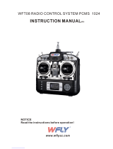
Airplanes with significant carbon fiber construction can create an RF shielding
effect, reducing range. The AR8020T is designed to overcome these critical
RF issues in carbon airplanes by outfitting the aircraft with two external
antennas at specific points that will ensure secure RF coverage from all
angles of the aircraft.
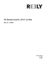
The AR8020T incorporates two feeder antennas; one antenna is 6.10 inches
(155 mm) and the second antenna is 7.32 inches (186 mm). They are
designed to be easily mounted through the fuselage in carbon airplanes. Each
feeder antenna includes acoaxial portion and an exposed 31mm tip antenna.
The last 31mm is the active portion of the antenna.
186mm31mm
155mm31mm
Smart Throttle
The AR8020T receiver throttle port includes Smart Throttle. When equipped
with Smart Throttle the normal servo connector delivers the throttle signal
to the ESC, plus the ESC can send telemetry data like voltage and current
back to the receiver. The AR8020T receiver throttle port will automatically
detect when a Smart Throttle compatible ESC is plugged in and the throttle
port will begin to operate in Smart Throttle mode.
ESCs with Smart Throttle and IC3
®
and IC5
®
connectors can also pass
along battery data from compatible Spektrum Smart batteries.
If a standard ESC or servo is plugged into the throttle port on the AR8020T
receiver, the throttle port will operate normally (PWM signal) like any
conventional RC system. The AR8020T receiver is compatible with the
Spektrum Avian line of ESCs for Smart Throttle.
For Smart Throttle to function you must have a Smart Throttle ESC paired
with a Smart Throttle telemetry receiver, and a Spektrum DSMX transmitter
with telemetry. An update for your transmitter may be required for Smart
features. See www.spektrumrc.com to register and update your transmitter.

12 SPEKTRUM NX8 • TRANSMITTER INSTRUCTION MANUAL
EN
External Antennas
Full Carbon
Installing the Receiver
Install the receiver in the normal position recommended by the airplane’s
manufacturer. Double-sided tape or foam can be used to secure the
receiver in place.
TIP: The hard case can be removed to help the AR8020T fit into a slim,
carbon fuselage. It is recommended to cover the bare receiver in heat
shrink.
Mounting the Antennas
To install the antennas, drill two 1/16-inch holes in the desired antenna
mounting positions.
Slide the feeder antennas through the holes until the 31mm tip, and about
2mm of coaxial, completely exit the fuselage. Use adrop of CA or tape to
fix
the antenna to the fuselage.
IMPORTANT: Ensure that the 31mm active portion of each antenna tip
is fully exposed.
TIP: Use the optional (sold separately) Antenna Exit Guides to safely
mount the antennas outside of the fuselage.
IMPORTANT: If the antenna is to be mounted internally (in the front
of a2.4GHz fuse), the coaxial can be taped into position. Ensure the
31mm tip is located at least 2 inches from any significant metal or
carbon structure.
Check that at least one
antenna will always be in
the RF visual line of sight
of the transmitter (e.g.
not blocked by carbon
fiber structures) in all
attitudes. This can easily
be visualized by having
a helper stand about 20
feet away and rotate the airplane in all attitudes, confirming that there is a
direct line between you and at least one receiver antenna that isn’t blocked
by carbon fiber structure.
Binding
The AR8020T receiver must be bound to your transmitter before it will
operate. Binding is the process of teaching the receiver the specific code of
the transmitter so it will only connect to that specific transmitter. When new
out of the package, the AR8020T will automatically go into bind mode the
first time it is powered on.
1. Connect the optional SRXL2 remote receiver (SPM9747 or SPM4651T) if
desired and any telemetry sensors to the main receiver.
2. Push and hold the bind
button on the receiver
while turning the
receiver on. Release
the bind button once
the orange LED starts
to flash continuously,
indicating that the
receiver is in bind
mode.
TIP: It is still possible to
use a bind plug in the
BIND port if desired. This
can come in handy if the
receiver needs to be mounted in a location that is difficult to access, in
which case a servo extension may be used for binding. If using a bind
plug, remove after binding to prevent the system from entering bind
mode the next time the power is turned on.
3. Put your transmitter in bind mode. Bind mode is accessible from the
System menu, Function menu, or with thEe bind button. To put the
transmitter in bind mode with the bind button, press and hold the bind
button while you power the transmitter ON.
Failsafe
In the unlikely event that the radio link is lost during use, the receiver
will enable the selected failsafe mode. Smart Safe + Hold Last is the
default setting on the AR8020T. Preset Failsafe and SAFE Failsafe are only
available through forward programming.
SmartSafe
+
Hold Last
If loss of signal occurs, SmartSafe™ technology moves the throttle channel
to its preset failsafe position (low throttle) that was set during binding. All
other channels will hold their last position. When the receiver detects the
signal from the transmitter, normal aircraft operation resumes.
4. The bind process is complete when the orange LED on the receiver is solid.

13SPEKTRUM NX8 • TRANSMITTER INSTRUCTION MANUAL
EN
Forward Programming
In your transmitter menu select Forward Programming -> Settings ->
• Select Failsafe -> Select each channel and assign it to Preset or Hold Last.
When you select a different channel for Output, a new group of settings
appears.
Capture Failsafe Postions ->
Hold the control sticks in the desired failsafe positions and select Apply.
Channel selections must be individually set in Forward Programming to
apply the preset positions or each channel will default to Hold Last. The
value captured will be reflected in the position shown for each channel.
• Initiate Receiver Bind Mode
Gives you the option of putting the receiver into Bind Mode from this
menu.
Preset Failsafe
With preset failsafe, you can set the specific control surface positions you
want to use if the signal is lost. When the receiver detects the signal from
the transmitter, normal aircraft operation resumes.
Only available through Forward Programming
Testing Failsafe
Secure the aircraft on the ground and remove the propeller. Test Failsafe
settings by turning the transmitter RF output off and noting how the
receiver drives the control surfaces.
Receiver Power Only
• If the receiver is turned when no transmitter signal is present, the
throttle channel will not have a control signal to avoid operating or
arming the electronic speed control.
• All other channels have no output until the receiver has linked to the
transmitter.
Receiver Power System Requirements
Inadequate power systems that are unable to provide the necessary
minimum voltage to the receiver during flight have become the number
one cause of in-flight failures. Some of the power system components that
affect the ability to properly deliver adequate power include:
• Receiver battery pack (number of cells, capacity, cell type, state of
charge)
• The ESC’s capability to deliver current to the receiver in electric aircraft
• The switch harness, battery leads, servo leads, regulators etc.
The AR8020T has a minimum operational voltage of 3.5 volts; it is highly
recommended the power system be tested per the guidelines below.
Recommended Power System Test Guidelines
If a questionable power system is being used (e.g. small or old battery,
ESC that may not have a BEC that will support high-current draw, etc.), it is
recommended that a voltmeter be used to perform the following tests.
View the receiver voltage during this test on your transmitters telemetry
screen, load the control surfaces (apply pressure with your hand) while
monitoring the voltage at the receiver. The voltage should remain above 4.8
volts even when all servos are heavily loaded.
How QuickConnect
™
Technology Works
• When the receiver voltage drops below 3.5 volts, the system ceases to
operate.
• When power is restored, the receiver immediately attempts to
reconnect.
• If the transmitter was left on, the system reconnects typically in about
4/100 of a second.
QuickConnect is designed to allow you to fly safely through most short
duration power interruptions, however, the root cause of these interruptions
must be corrected before the next flight to prevent a crash.
NOTICE: If a brownout occurs in flight it is vital that the cause of the
brownout be determined and corrected.
IMPORTANT:
When using Y-harness or servo extensions with Spektrum
equipment, do not use reversing harnesses. Using reversing Y-harnesses
or servo extensions may cause servos to operate erratically or not
function at all.
Flight Log
Flight Log data can help you optimize the control link for your aircraft. Flight
Log data is displayed on your NX8.
Using the Flight Log
A - Fades on main receiver. B - Fades on remote receiver
L - Not available on AR8020T R - Not available on AR8020T
F - Frame losses H - Holds
Fades
Represents the loss of one bit of information on one receiver. Fades are
used to evaluate the performance of each individual receiver. If any single
receiver displays higher fade values it should be inspected and the antenna
repositioned to optimize the RF link.
Frame Loss
A frame loss occurs when one complete data packet is missed. A single
frame loss does not represent a loss of control, but frame losses should
be monitored. In the air it's normal to experience as many as 100 frame
losses per minute of flight. On the ground the number of frame losses will
be higher because the signal is hampered by earth and moisture.
Hold
A Hold occurs when 45 consecutive frame losses occur. This takes about
one second, and in this event the receiver moves the channel outputs to
the failsafe settings. If a hold ever occurs, it’s important to re-evaluate the
system and check every component. If your system displays a hold taking
place, diagnose the cause and resolve the issue before flying again.
It is normal to see a hold logged if you power OFF your transmitter and back
ON.
IMPORTANT: The Spektrum Flight Log (SPM9540) is not compatible
with the AR8020T receiver.

14 SPEKTRUM NX8 • TRANSMITTER INSTRUCTION MANUAL
EN
Range Testing
Before each flying session, and especially with a new model, it’s important
to
perform a range check. All Spektrum aircraft transmitters incorporate a
range testing system, which reduces the output power to allow a range
check.
1. With the model resting on the ground, stand approximately 100 feet (30
meters) away from the model.
2. Face the model with the transmitter in your normal flying position and
put your transmitter into range test mode.
3. You should have total control of the model in range test mode at 100
feet.
4. If control issues exist, call Horizon Product Support for further
assistance.
Advanced Range Testing
The Standard Range Testing procedure is recommended for most sport
aircraft. For sophisticated aircraft that contain significant amounts of
conductive materials (e.g. turbine powered jets, scale aircraft with
metallized finishes, aircraft with carbon fuselages, etc.), the following
advanced range check will confirm that all receivers in the system are
operating optimally as installed. This advanced range check allows the RF
performance of each receiver to be evaluated independently. A telemetry
equipped Spektrum Transmitter is required for the advanced range test.
1. Stand approximately 100 feet away from the model.
2. Face the model with the transmitter in your normal flying position and
put your transmitter into range test mode.
3. Have a helper position the model in various orientations (nose up, nose
down, nose toward the transmitter, nose away from the transmitter,
etc.).
4. Observe the telemetry on your transmitter. Note any orientations that
cause higher fades or frame loss values. Perform this step for at least
one minute.
5. Re-position any antennas related to higher fades as necessary.
6. Re-test to verify satisfactory results.
7. Repeat as necessary.
After one minute, advanced testing should yield:
H - 0 holds
F - less than 10 frame losses
A, B - Fades will typically be less than 100. It’s important to compare the
relative frame losses. If a particular receiver has a significantly higher frame
loss value (2 to 3X) then the test should be redone. If the same results
occur, move the offending receiver to a different location.
TIP: Use the fade values for A to investigate the performance of the telemetry link.
Optional Accesories
SPMA3065 USB Programming Cable
Telemetry Sensors and Accessories
SPMA9574 Aircraft Telemetry Airspeed Indicator
SPMA9587 Aircraft Telemetry GPS Sensor
SPMA9604 Aircraft Telemetry Receiver Battery Energy Sensor
SPMA9605* Aircraft Telemetry Flight Pack Batt Energy Sensor
SPMA9551 12" Aircraft Telemetry Extension
SPMA9552 24" Aircraft Telemetry Extension
*For use with electric power system batteries that are separate from the
receiver battery(s).
Telemetry
The AR8020T features full range telemetry and will provide receiver battery
voltage, flight log data, and vario and altitude data without any additional
sensors. The altitude and vertical speed (variometer) sensor (
SPMA9589)
functions are already integrated in the SPMAR8020T.
Additional telemetry
devices such as voltage sensors can be connected to the volt port, and
XBus telemetry sensors can be connected through the XBus connector.
Every XBus telemetry device has two XBus ports, and XBus telemetry
sensors can be connected in a daisy chain in any order.
The AR8020T is not compatible with the Spektrum Temperature Sensor
(SPMA9571)
See www.spektrumrc.com for more information about telemetry accessories

15SPEKTRUM NX8 • TRANSMITTER INSTRUCTION MANUAL
EN
MODEL TYPE PROGRAMMING GUIDE
Menu options show up on model type selection. These menu options vary between Model Types (Airplane, Helicopter,Sailplane and
Multirotor), but are identical for all models in that type. Subsequent aircraft type (Aircraft, Swashplate, Sailplane or Multirotor) selections
make other menu options appear.
System Setup List:
Model Select
Model Type
Model Name
Aircraft Type
F-Mode Setup
Spoken Flight Mode
Channel Assign
Trim Setup
Model Utilities
Warnings
Telemetry
Preflight Setup
Frame Rate
Bind
Serial Port Setup
Trainer
Analog Switch Setup
Digital Switch Setup
Center Tone
Sound Utilities
System Settings
WiFi Utilities
USB Settings
Transfer SD Card
About/Regulatory
Function List:
Servo Setup
D/R and Expo
Differential
V-Tail Differential
Throttle Cut
Throttle Curve
3–Axis Gyro
Gyro (1,2,3)
Flap System
Mixing
Sequencer
Range Test
Timer
Telemetry
Forward Programming
Audio Events
VTX Setup
Function Bar
Start Timer
System Setup
Monitor
System Setup List:
Model Select
Model Type
Model Name
Sailplane Type
F-Mode Setup
Spoken Flight Mode
Channel Assign
Trim Setup
Model Utilities
Warnings
Telemetry
Preflight Setup
Frame Rate
Bind
Serial Port Setup
Trainer
Analog Switch Setup
Digital Switch Setup
Center Tone
Sound Utilities
System Settings
WiFi Utilities
USB Settings
Transfer SD Card
About/Regulatory
Function List:
Servo Setup
D/R and Expo
Differential
V-Tail Differential
Throttle Cut
Motor Curve
Camber Presets
Camber System
Mixing
Sequencer
Range Test
Timer
Telemetry
Forward Programming
Audio Events
VTX Setup
Function Bar
Start Timer
System Setup
Monitor
System Setup List:
Model Select
Model Type
Model Name
Aircraft Type
F-Mode Setup
Spoken Flight Mode
Channel Assign
Trim Setup
Model Utilities
Warnings
Telemetry
Preflight Setup
Frame Rate
Bind
Serial Port Setup
Trainer
Analog Switch Setup
Digital Switch Setup
Center Tone
Sound Utilities
System Settings
WiFi Utilities
USB Settings
Transfer SD Card
About/Regulatory
Function List:
Control Setup
D/R and Expo
Motor Cut
Motor Curve
Mixing
Sequencer
Range Test
Timer
Telemetry
Forward Programming
Audio Events
VTX Setup
Function Bar
Start Timer
System Setup
Monitor
System Setup List:
Model Select
Model Type
Model Name
Swashplate Type
F-Mode Setup
Spoken Flight Mode
Channel Assign
Trim Setup
Model Utilities
Warnings
Telemetry
Preflight Setup
Frame Rate
Bind
Serial Port Setup
Trainer
Analog Switch Setup
Digital Switch Setup
Center Tone
Sound Utilities
System Settings
WiFi Utilities
USB Settings
Transfer SD Card
About/Regulatory
Function List:
Servo Setup
D/R and Expo
Throttle Cut
Throttle Curve
Pitch Curve
Swashplate
Gyro
Tail Curve
Mixing
Sequencer
Range Test
Timer
Telemetry
Forward Programming
Audio Events
VTX Setup
Function Bar
Start TimerSystem Setup
Monitor
System Setup List:
Model Select
Model Type
Model Name
Aircraft Type
F-Mode Setup
Spoken Flight Mode
Channel Assign
Trim Setup
Model Utilities
Warnings
Telemetry
Preflight Setup
Frame Rate
Bind
Serial Port Setup
Trainer
Analog Switch Setup
Digital Switch Setup
Center Tone
Sound Utilities
System Settings
WiFi Utilities
USB Settings
Transfer SD Card
About/Regulatory
Function List:
Servo Setup
D/R and Expo
Differential
V-Tail Differential
Throttle Cut
Throttle Curve
3–Axis Gyro
Gyro (1,2,3)
Flap System
Mixing
Sequencer
Range Test
Timer
Telemetry
Forward Programming
Audio Events
VTX Setup
Function Bar
Start Timer
System Setup
Monitor
System Setup List:
Model Select
Model Type
Model Name
Sailplane Type
F-Mode Setup
Spoken Flight Mode
Channel Assign
Trim Setup
Model Utilities
Warnings
Telemetry
Preflight Setup
Frame Rate
Bind
Serial Port Setup
Trainer
Analog Switch Setup
Digital Switch Setup
Center Tone
Sound Utilities
System Settings
WiFi Utilities
USB Settings
Transfer SD Card
About/Regulatory
Function List:
Servo Setup
D/R and Expo
Differential
V-Tail Differential
Throttle Cut
Motor Curve
Camber Presets
Camber System
Mixing
Sequencer
Range Test
Timer
Telemetry
Forward Programming
Audio Events
VTX Setup
Function Bar
Start Timer
System Setup
Monitor
System Setup List:
Model Select
Model Type
Model Name
Aircraft Type
F-Mode Setup
Spoken Flight Mode
Channel Assign
Trim Setup
Model Utilities
Warnings
Telemetry
Preflight Setup
Frame Rate
Bind
Serial Port Setup
Trainer
Analog Switch Setup
Digital Switch Setup
Center Tone
Sound Utilities
System Settings
WiFi Utilities
USB Settings
Transfer SD Card
About/Regulatory
Function List:
Control Setup
D/R and Expo
Motor Cut
Motor Curve
Mixing
Sequencer
Range Test
Timer
Telemetry
Forward Programming
Audio Events
VTX Setup
Function Bar
Start Timer
System Setup
Monitor
System Setup List:
Model Select
Model Type
Model Name
Swashplate Type
F-Mode Setup
Spoken Flight Mode
Channel Assign
Trim Setup
Model Utilities
Warnings
Telemetry
Preflight Setup
Frame Rate
Bind
Serial Port Setup
Trainer
Analog Switch Setup
Digital Switch Setup
Center Tone
Sound Utilities
System Settings
WiFi Utilities
USB Settings
Transfer SD Card
About/Regulatory
Function List:
Servo Setup
D/R and Expo
Throttle Cut
Throttle Curve
Pitch Curve
Swashplate
Gyro
Tail Curve
Mixing
Sequencer
Range Test
Timer
Telemetry
Forward Programming
Audio Events
VTX Setup
Function Bar
Start TimerSystem Setup
Monitor

16 SPEKTRUM NX8 • TRANSMITTER INSTRUCTION MANUAL
EN
Enter the System Setup menu to define baseline settings for your model such as what type of aircraft, wing type, flight mode setup, etc.
The options chosen in the system menu configures the function list for the chosen model number for your requirements. Some options,
such as the flap menu, will not appear at all in the function list until they are selected within the System Setup menu.
Press and hold the scroll wheel while powering on the transmitter to show the System Setup list. No radio transmission occurs when a
System Setup screen is displayed, preventing accidental damage to linkages and servos during changes to programming.
You can also enter the System Setup from the Function list without turning the transmitter off. A caution screen will appear that warns
that RF will be disabled (the transmitter will no longer transmit). Press YES if you are sure and want to access the System List. If you are
not sure, press NO to exit to the main screen and continue operation.
Model Select enables you to access any of the 250 internal model
memory locations in the Model Select list.
1. Scroll to the desired model memory in the Model Select list.
2. When the desired model memory is highlighted, press the
scroll wheel once to select the model. The transmitter returns
to the System Setup List.
3. Add a new model by rolling to the bottom of the list. You will
then be prompted with the Create New Model screen, with
the option to create a new model or cancel. If you select
Cancel, the system will return to the Model Select function. If
you select Create, the new model will be created and now be
available in the model select list.
Direct Model Access
Press the Clear and Back buttons from the Main Screen or a
telemetry screen to access Model Select.
SYSTEM SETUP
Select from Airplane, Helicopter, Sailplane or Multicopter model types.
IMPORTANT: When you select a new model type, you will
delete any programming data in the current model memory.
Always confirm the desired model memory before changing
model types. It will be necessary to re-bind after resetting the
model type.
To change the model type:
1. Scroll to the desired model type and press the scroll wheel.
The Confirm Model Type screen appears.
2. Select Yes and press the scroll wheel to confirm the model
type. All data will be reset. Selecting No will exit the Confirm
Model Type screen and return to the Model Type screen.
Model Select
Model Type
WARNING: Do not press YES unless the model is turned
off or the model is secured.
If you do not press YES or NO, the system will exit to the main
screen and continue operation within approximately 10 seconds.

17SPEKTRUM NX8 • TRANSMITTER INSTRUCTION MANUAL
EN
Use the Flight Mode Setup menu to assign switches to flight modes.
Flight Mode Setup
You can assign up to ten flight modes using any combination of up
to three switches, maximum flight modes and switches available
dependent on model type. You can also assign a priority switch.
When the priority switch position is active, only the current flight
mode is active, regardless of other switch positions.
Aircraft Flight Mode Table
You can assign the available flight modes to each of the switch
positions (up to 3 switches can be used for Aircraft/Sailplane).
Press NEXT from the Flight Mode Name page to access the flight
mode table assignment page when Custom flight mode has
been selected in the Flight Mode Setup page. The combination of
switches can be used to access all of the flight modes available.
Below is an example of 5 flight modes, you can configure up to
10 flight modes with the NX8:
Number
of Flight
Modes
2 3 3* 4 4 5
Switch 1
(number of
positions)
2P 3P 2P 2P 3P 3P
Switch 2
(number of
positions)
2P 3P 2P 3P
Flight
Mode
1
Launch Launch Launch Launch Launch Launch
2 Cruise Cruise Cruise Cruise Cruise Cruise
3 Land Land Land
4 Thermal Thermal Thermal Thermal
5 Speed Speed
* Must be set up in a 4/5 flight mode.
Model Name enables you to assign a custom name to the current
model memory. Model names can include up to 20 characters,
including spaces.
To add letters to a Model Name:
1. Scroll to the desired letter position and press the scroll wheel
once. A flashing box appears.
2. Scroll left or right until the desired character appears. Press
the scroll wheel once to save the character.
3. Scroll to the next desired letter position. Repeat Steps 1 and
2 until the Model Name is complete. Insert a character by
selecting <+> or delete a character by selecting <->.
4. Select BACK to return to the System Setup list.
To erase a character:
1. Press CLEAR while the character is selected.
2. Press CLEAR a second time to erase all characters to the right
of the cursor.
Aircraft Type
This menu is only available in Airplane Mode. See ACRO (Airplane) section for set up.
Sailplane Type
This menu is only available in Sailplane Mode. See SAIL (Sailplane) section for set up.
Swash Type
This menu is only available in Helicopter Mode. See HELI (Helicopter) section for set up.
Aircraft Options
This menu is only available in Multirotor Mode. See MULTI (Multirotor) section for set up.
Model Name
F-Mode Setup
Mode Number of Switches Number of Flight Modes
ACRO 3 10
HELI 3 (including Throttle Hold) 5 (including Throttle Hold)
SAIL 3 10
MULTI 2 5

18 SPEKTRUM NX8 • TRANSMITTER INSTRUCTION MANUAL
EN
Enables you to assign custom names to the Flight Mode positions.
Flight Mode names can include up to 20 characters, including
spaces.
To change the Flight Mode name:
1. Scroll to the Flight Mode name you wish to change and press
the scroll wheel.
2. Scroll to the character position you wish to change and press
the scroll wheel once. A flashing box appears.
3. Scroll left or right until the desired character appears. Press
the scroll wheel once to save the character. Insert a character
by selecting <+> or delete a character by selecting <->.
4. Repeat Steps 2 and 3 until the Model Name is complete.
5. Select BACK to return to the Flight Mode Names list.
The Channel Assignment function allows you to reassign almost
any receiver channel to a different transmitter channel. For
example, the receiver gear channel could be re-assigned to the
transmitter throttle channel.
1. Scroll to the receiver channel you wish to change.
2. Press the scroll wheel once and scroll left or right to change
the receiver input selection.
3. Press the scroll wheel a second time to save the selection.
IMPORTANT: You cannot assign a mix to a channel that has
been moved. Create the mix first, then move the channel.
The Channel Input Configuration screen enables you to assign a
transmitter channel to a different control stick or switch.
1. Select NEXT on the RX Port Assignments screen to access the
Channel Input Configuration screen.
2. Scroll to the transmitter channel you wish to re-assign and
press the scroll wheel. The box around the current input
selection flashes.
3. Scroll left or right to select the desired control stick or switch.
4. Press the scroll wheel to save the selection.
Flight Mode Setup
Channel Assignment
Channel Input Configuration

19SPEKTRUM NX8 • TRANSMITTER INSTRUCTION MANUAL
EN
Trim Setup
Use the Trim Setup screen to change the size of the trim step and
the trim type.
Trim Step
Adjusting the trim step value determines how many “clicks” of trim
you input each time you press the trim button. Changing the trim
step value to 0 disables the trim for the channel.
To change the trim step value:
1. Scroll to the trim step channel you wish to change.
2. Select the trim step value and scroll left or right to change
the value.
3. Press the scroll wheel to save the selection.
Trim Type
The two Trim Type options are Common and F Mode.
Common trim type maintains the same trim values for all
flight modes.
F Mode trim type enables you to save trim values for individual
flight modes if you find, for example, the aircraft requires aileron
trim in Flight Mode 1 but not in Flight Mode 2.
Trim Assignment
In a few instances, you can reassign a trim to a different
location.
Aircraft Model Type
Throttle
• Throttle Digital trim button (default)
Left Lever
Right Lever
Throttle Trim Type
• Common
• Flight Mode
Trim Location
Normal and Cross trim types are available. Normal trims align with
the control stick; for example, the throttle trim is next to the throttle
stick.
Cross trims reverse the position of the trims; for example, the
throttle trim is next to the elevator stick and vice versa.
To change the Trim Position from Normal to Crossed, select Normal
at the bottom of the Trim Setup screen and press the scroll wheel.
IMPORTANT: Crossed trims will cross both sets of trims for
both gimbals.

20 SPEKTRUM NX8 • TRANSMITTER INSTRUCTION MANUAL
EN
Delete Model
Use this selection to permanently delete a model from the model
select list. If you do not wish to delete a model, select Cancel to
exit the page.
1. To delete a model, highlight the model listed. Press to select,
then roll to the model name. Press the scroll wheel to select.
2. Select DELETE to delete the model.
Create New Model
Use this selection to create a new model in the model select list.
1. Select Create New Model. Within this screen, you will have the
option to create a new model or cancel.
2. Select the model type. Choose the aircraft image to define the
model type for a blank model file, or select Template to load
a template file. A SAFE template and a SAFE Select template
come pre-loaded on your NX8.
• Templates are saved in the templates folder on the internal
memory (accessible with the USB connection, new .NSPM files
may be added)
• The SAFE template puts the 3 position flight mode switch
(Channel 5) on switch B. The Panic button is on the I button
(Channel 6). SAFE airplanes have a fixed configuration in the
receiver and will match this setup after binding.
• The SAFE Select template uses the D switch for flaps
(Channel 5), the A switch for retracts (Channel 6), and the
B button to turn SAFE select ON or OFF (Channel 7). Selecting
this template alone will not enable SAFE Select, it must be done
during the bind process. Also, the switch must be assigned in
the receiver after binding, and the flap travel values need to be
applied. See your airplane manual for more information.
3. If you select Cancel, the system will return to the Model Select
function.
4. If you select Create, the new model will be created and now
be available in the model select list.
WARNING: Complete a preflight check before
attempting to fly any model with a new model file or
template. If you have the controls set up incorrectly for your
aircraft, it may result in loss of control and a crash.
Select the BNF model type setting to access a list of pre-
configured model files for Horizon Hobby BNF aircraft.
In the Model Utilities function you can create a new model, delete
a model, copy a model, reset a model to default settings and sort
the model list.
Model Utilities
/