Page is loading ...

;¿:
.:\;J
u
j-L)
4 l!:,#,f,:¡9,:", I::
h n 0 I 0
s
¡ e s'"
APOLLW
O
2000
by UPS
Aviation
Technolog,es.
2345 Turner
Rd..
S.E.
Salem, OR
97302 U.S.Å.
Phone 503.581.8':-
800.s25.ô72ô
ln
Canada
834.êi:.3-:':
FAX 5C3 3a:2'a.a
httc: ,,;¡;,,, .
-:
s¿'- :a
-
Pa:
=5€
--'
-24--'-
-=
-=
t
a---
4
i::
,rlk¿C:,t
t'i,t"!t)
li.[l
ilþ
F
I
r
]ttjÐr.r
.lrE
?]t..1
U>e/* 9lrile
^
y!:
#lîJ'l,T"
.I":,:"
n0 I
0s¡ es
-


End User
Liceqse
Asreemenr
(-EULi-
lìcluntl.
Il'vourlonorrgrccrorhctcrmsof'thisEUL{UPS-l,vi:::::-l:,-.:::.:::,::.:
l.-.:::..::
arc
unwilling to liccnsc
rhc \f
X20 and irs
Opcrating
Svstcm
io
r
¡:.
I:. i:::
....::- . _
-:.
:
-:
usc or copy
thc Liccnscd Product,
and you
should promprlv
con¡¿c:
U?S
-:.r:::::
l::---::.:.:::
fòr i¡rstrrrctions
on rcrurn
of'thc
unuscd
product(s)
lor a rcfund.
Clicnt
Acccss Liccnscs.
If you
usc thc MX20
Opcratin.q
Svstcm
ro :cJcs: ;:
:::.-:: :-1:
hrnctionality
of Microsolt Winclows
N'I'Scrucr
(all
cditions) or
usc ihc \Í\l
i:.::.:
to
pcrmit works(ation
or
computing
dcviccs ro
acccss or
utilizc rhc scli¡c:
::::
ì\4icrosofi Windows
NT
Scrucr, you mâ),
lrc rc<¡uircd
to
obr¡in a Clicn:.{:::ss
]::::.:.: ::::-::
ìVlX20 Opcrating
Sysrcm
a¡r<ì/or
cach suclr uorkstation
or
computing
Cc...icc.
No
Warrantics.
Exccpt
as cxprcssly providcd
in
thc limitcd \\:arranr\.scciion.:ic
I1-\j ::: .:,
opcratingsvsrcmarcprovitlccl(oyou"asis"u,ithoutwarrantloianrkini.ci:l:::r:::r:::::
implicd, incluiling,
but
not limirctì
to,
rvarranrics
of noninf-ringcmcnt.
mc:ci:3i::::.i:.
::.: : :
fìtncss fòr
a parricular purposc.
thc
cntirc risk
of rhc quality
and pcrt-ormancc
oi:ir
r::,.::: .:
u
ith thc
r¡scr.
No
l-iability for
Conscqucntial
f)amagcs.
UPS Aviation
Tcchnologics
anC
o: L?S .ir:::::.
Tcchnolocics'
soft*'arc
supplicrs shall
not
bc hcld liablc
for anv damagcs
surìèrcd
o: i::::::j
:.
you
(including,
l¡ut not limitcd
to, gcncral,
spccial,
conscqucntial
or
inciicn::.
j::_:::,
inclutling
darnagcs
lor loss ofbusincss
profìts,
busincss
intcrruption,
loss oibusincss
ir:':-.:::::
anrl thc likc),
arising frorn
or in conncction uith
thc dclivcry,
usc, or pcrf'ormancc
oi:ht sc::.,.:--:
(ìustomcr
llcmcdics.
UPS Aviation
'lcchnologics'
and
UPS Aviation Tcchnolo,gics
::::.:::,
cntirc
liability and your
cxclusivc
rcmcdv shall
bc, at
UPS Aviation
Tcchnologics
o::i.:.
:::_r::
(a)
rcturn ol
thc pricc paid,
or
(b)
rcpair
or rcplaccmcnt
of
rhc lvf X20 and
irs oæ:¿:j:-:
:.::::-
that tlocs
not mccr
thc abovc
Limitcd
Warranty
and which
is
rcturncd ro
UpS
-r-..::::::
'l'cchnologics
rvith
a
co¡ry of your rcccipt.
This
Limitcd
warrantl,is
void
if tàilurc
oi:ic \1.\j. ::
its opcrating
systc¡n hâs
rcsultcd fìorn
accidcnt, abusc,
or misapplication..{.nr.rc¡la¡c:::.:
l.l-r.-
and its
opcrating svstcnr rvill
lrc warra¡rtctl
fòr
thc rcmai ndcr
of thc original \\
l::an:.
:<i
:.: : :
thiny
(30)
days. u'hichcvcr
is longcr.
[-imitations
on Iìcvcrsc
Enginccrin{¿,
l)cconrpilation
and
Disasscmblr'.
)'ou n¿.
::: :.-::.:
cnginccr.
clccompilc,
or disasscmblc
rhc MX20
or its
opcrating s\'srcm.
crcîi: ::.:
::-.. : _ :- :
cxtcnt tlìat
suclì âctivitv is
cxprcssly pcrmittcd
by
applicablc lalv
notu.ithsranCin;
:lis .i:.:::.:::
Scprration
of Componcnrs.'fhc
MX20 and
its opcrating svsrcm
arc liccnsci
:s : :::.-¡.:
;::,:
_:-
Its componcnt pans
may
not bc scparatcd
f'or usc
on morc
thrn onc \fX20.
Sin{¡lc Flmbcddcd
Svsrc¡n.
1'hc ìVfX20
and its opcrating
svsrcm
arc Iiccnscc
..,.i::,
--j::
singlc
irrtcgratcd product.'fhc
ì\,fX20 opcrating
sysrcm
ma\.onlv
bc uscj..,.i:i::.:
l
fònh in
thcsc liccnsing
tcrms.
Wclcomc
to
a
ncw
era
of aviation
navisâtion.
Oncc
again,
UPS
Aviation
Technologies,
Inc.
has
scr
ncw
srandârds
in
features
and
ease
of
use
for
the
general
aviation
public.
The
Apollo
MX20
Multi-Function
Display
providcs
a
focal
point
for
intcgrating
many
of your
nauigation
nccds
rn
an
easy
to
use
and
convenicnt
packagc.
Thc
MX20
prcsenrs
a
wealrh
of
information
on irs
six-inch
diagonal,
640x480
pixcl,
color
display.
Thc
many
fcaturcs
are
org
nized
as
distinct
functions
and
¿ìrc
designed
to closely
mimic
thc
traditional
instrumcnrs
uscd
in
the
srandard
cockpir.
Each
finction
allows
varying
dcgrees
of customization.
Thc
custom
map
function
is
customizablc
so
you
can
create
a
display
for
almost
any
confìgurarion
you
requirc.
Thc
other
functions
provid;
more
limited
levels
of
customization
so
that
thcy
rctain
the
look
and
feel
of
the
instrumcnrs
rhcy
rcflccr.
The
MX20
is
capablc
of
creating
powcrful
ovcrlay
vicws
where
information
from
a varicty
of
sourccs
can
bc
presented
simultaneously
in
propcr
rclationship
ro
cach
other,
thus
grcarly
incrcasing
situational
awarcncss
for
thc
pilor.
You
can
bc
confidcnt
in
knowing
that you
arc
thc
owncr
of
the
srare-oÊrhe-arr
in
aviation
and
navisation.
Thc
MX20
archirecure
is
dcsigned
ro
supporr
full
cxpansion
for
both
softwarc
and
hardware
cnhanccmcnts.
This
flexibility
prorccrs
your
invcsrmenr
and
allows
for
thc
casc
of
adding
new
features.
Our
producrs
arc
buik
to last
ancl
to
allow
the
flexibility
ro meer
your
nccds
as
rhcy
changc
in
thc
future.
'Welcome...
ia:::a:
::
::
j.
¡':,:
e)
.ê
.F
¿a
.F
eF
e-
arr^
o-
ar--
J-
a,)
ar-
er-^
j-
Ot--
er--
o)
er-^
O'-^
er--
a)
ar-.
a)
a)
G)
J)
t)
a)
or.^
et,.
J,-
f
J.-
J-a
eâ
a,'t
é

About
This
Manual
This
manual
may
be
used as
a
summary,
a
reference.
and
a
learning
tool.
Information
is provided
about
all
of the
functions
available
to the
MX20.
Your
specific
installation
may
not
include
all
of
these functions.
Take
a
few moments
to
familiarize
yourself
u.irh
rhe
various
sections
in
this
manual.
The
Getting
Staned
section
gives
an introduction
to thc
controls.
basic
operation,
and
organization
of the
functions
in
r.our
MX20.
Be
sure
ro read
the
Getting
Started
secrion
ro
learn
the rules
for
using
the
MX20.
The
Detailed
Operation
section
is the
referencc
for
each
of the
functions
in
rhe
MX20.
Refcr
to the
Detailed
Operation
section u,hen
r.ou
want
to get
into
the
details
on
every
function
and option
along
with
srep-by-step
instructions.
Not
every
function
is
available
in
all
software
versions
or
installations.
Check
your
Approved
Flight
\,f anual
Supplemcnt
to verify
the
features
that
are
available
.
Table
of
Contents
History
of Revisions
?
c)
e)
Jâ
ê
er-.
J)
J)
eâ
J-
J-
Jr-
J,-
J)
e-
J-
Jr-.
erf.
J)
e-
J)
e)
o,-
et)
or)
et)
ar-
o)
ar-
e)
or-
a)
J-
e-
or-
ar-
.-
J-
J'-
Jr-
Jr-
a,a
e
..
I
Ordcring
Information
About
This
Manual
Welcome.
AboutThisManual....
iv
Getting
Started
Functions.
Controls
PowerÆrighrness
.
Function
(FN)
.
,t
iii
MenuÆnter
Line
Selcction
.
Data
Card
Display
Annunciations
.
Advisory
Flags.
.
Traffic.
Terrain
Lightning
Data
Flags
Mcssage
Flag
.
3
3
J
4
4
7
8
8
9
5
6
7
7
7
7
Basic
Operation
Power
On
Pre-Heat
Modc
. .
Brightness
Start
Up
Screen
Confirm
Current
Baro
Correction
.
Function
Selection.
Options
Menu
.
Summary
Detailed
Operation
9
9
l0
l0
lt
lt
t2
l3
l5
\fessagc
Log
(MSG)
Function
Custom
N{ap
(MAP)
Function

MapScale
. .
. . .l7
Pan.
.......18
Info..
.......
t8
FlightPlan..
...20
MapOrientation.
.....20
Invert.
.......21
NavData
......21
Terrain
..
-....22
Airports
.......23
VORS.
....
-..23
NDBs.
.......23
Intersections
....24
Airspace
....-.24
LowAirways.
.....2j
HighAirways
.
.....2j
Water
...2i
Roads.
.......26
Boundary.
.....26
Traffic
.......27
Strikes
.......27
IFRChartFunction
.
. . .
. . .
Zg
FlightPlan..
...2g
MapOrientation.
.....28
Invert.
.......29
NavData
......29
Label.
.......30
LowAirways....
...
. .30
HighAirways
.
. . .
.30
VFRChartFunction
.......31
FlightPlan..
...3t
MapOrientation.
.....31
Invert.
.......32
NavData
.
. . .
. .32
Label.
.......32
TrafficFunction
. .
. .33
aT
.Ð
cÐ
eÐ
é)
ê
€
eÐ
ê
ë
ë
e.
ë
ë.
é.
ê
ê
€
e.
€
ê
é.
ê
e.
é.
e)
€
€
€
€
c.
€
€
€
ê
é.
€
€
'
€
€
é_
TrafficDescription
. . . .
.33
FlightPlan..
.-.3j
TrafficMapOrientation
. . . .
. .35
TrafficAltitudeValues
...36
Display
Mode .
Graphic
....36
Text
.....36
AltitudeOption(RelativeÆressure)
.
.
. . . .
3Z
Time.
.......37
BroadcastFlightlD...
.......38
FlightlDEditing
......39
Flight
Plan
(FPL)
Funcion
. . . 40
Terrain(TER)Funcrion.
. .
-
.41
FlightPlan..
...43
TRKUpATcÆRKUp
360
SetBarometer
.
. . .
. .44
TERDataFlag..
......44
LightningStrikes(LT)Function.
. .
. . .
. . 45
FlightPlan.
.
.
. .46
360/t20
.......46
Lightning.
Strike.
.....46
Cell..
.....46
SystemDara.
.
. .46
Demo
...46
SelÊTest
.-....47
NoiseMonitor.
.
.....47
StrikeTest
. . . . .47
SystemFunction
.. .
.48
SystemNavPage
. .
. . . .48
OwnshipSymbol
.. .
.48
Lat/LonFormat.
....48
SetBaroCorrection.
. .
. . . . .49
DisplayLat/Lonlines.
. . . .
.49
Systemlnfo..
...50
SystemTestPage
. . .
. . .50
TestPanernl....
.......51

.
-rR.ed,
Green,
Blue,
Whitc
Tcst
pattern
Caring
For
Your
MX20
Display
Care
and
Cleaning
Troublcshooting
.
Gctting
Stancd
The
MX20
conrains
nine
major
separare
functions
for
the
tri-statc
(three
choices).
The
funcrions
are:
.
MSG
-
Message
Log
(See
page
16
for
details)
.
MAP
-
Custom
Map
(See
page
17
for
details)
.
IFR
- IFR
Chart
(See
page
28
for
dctails)
.
VFR
-
VFR
Chart
(See
page
3l
for
details)
r
Jft,{þ
-
Tlaflc
(ADS-B
instaÌlations
only)
(See
page
33 for
details)
o
FPL
- Flight
Plan
(See
page
40
for
dctails)
o
TER
-
Terrain (See
page
4l
for
details)
.
LT
- Lightning
Strikes (See
page
45
for
details)
.
SYS -
System
Information
(See
page
4g
for
details)
The
Message
Log
displays
information
from
the
MX20
or
reported
to
the
MX20
by
its
exrernal
sensors.
A flashing
ü7
G?
JF
JF
ap
J,+'
-F
t-
JF
JF
JF
EF
JF
JF
eF
-p
-+
JF
.â
J-
JF
J)
J,-
J)
etr^
Jr-
Jt-
Jr-
Jt-^
ê
J)
J)
--
ê
J-
J,-
J)
et-
ar--
J-
ar.
a,a
é
t1
tl
>?.
t3
This
section
explains
how
ro get
started
using
the
MX20.
Information
in
this
secrion
describes
the
controls,
data
card,
display,
and
basic
operation.
Aftcr
reading
this
section,
go
to
the
Detailed
Operation
section
for
expanded
explanations
for
each
feature.
Functions
display
of
information.
The
function
names
are
shown
as
"smarr"
keys
at
the
bottom
of
the
display.
The
.,smarr"
key
is
the
combinarion
of a
label
above
a
triangle
key
at
the
bottom
of
the
display.
The
labels
abovc
the
triangle
keys
change
to reflect
the
choices
available
ro
you
at
the
time
for
each
function.
Press
the
FN
key
to
show
the
available
functions.
Press
the
"smarr"
key
below
the
function
label
to go
to
the
displayed
function.
While
in
each
funcion,
press
the
MENU/ENTER
key
to
show
the
options
for
each
function.
The
options
are
shown
on
rhe
rþht
side
of
the
display.
Press
the
LINE
SELECT
key
to
manipulate
the
options.
Some
options
toggle
on/off,
while
some
are
viii
I
I

Gctting
Staned
Gctting
Stancd
MSG annunciator
notifies
you
of
a new
message rhar
should
be
viewed.
The Custom
Map function allou's you
to completely customize
the displayed map
by ovedaying
selected
information.
The
Custom Map can
become
"cluttered"
if
you
choose
every option, so use
discretion.
The IFR Chart function provides
an IFR enroure
sryle
map
on the display. The
VFR
Chart function provides
a
VFR
sectional style map
for the display. The
Traffic
function
(when
installed)
shows nearby
traffic and details
about each target.
The Flight
Plan
function
provides
details about
your
flight plan
and each waypoint.
The
Terrain function
shows a color coded
map of rerrain
elevation in relation
to
your
altitude.
The Lightning
function, when connected
to the
BF Goodrich
WX500
Stormscope,
controls the
overlay of lightning
strike
information
on the map
displays. The System
Information
function lets
you
set
general
preferences,
show software
version
information, and test
the display.
Controls
I
t_
Power/Brightness
The power
switch
is located
in
the upper right
corner
of
the
MX20. Turn
the power
rotary
knob clockwise
pasr
rhe
detent
to turn
the power
on. Turn
the power
knob fully
counterclockwise
to turn
the power
off.
With
the power
knob
pushed
in, the
brightness is
set automatically
according
to ambient
light
by a photosensor.
knob
out and
turn
the knob
to adjust
the
brightness
manually.
Function
(FN)
The
Function
keys are
made
up of
one dedicated key
on
the lower
left side
of the
display
and the four
"smart"
keys
to the right
of it.
Press the
function
(FN)
key
repeatedly
to
scroll
through
the available
functions.
The functions will
appear
above
the
"smart"
function
keys in
turquoise.
Function
Key
9mart Function
Keyø
5marl Key Labelø
Use
the FN
key to
display a list
of
the main functions,
such
as
Map,
IFR, Terrain,
etc.
Each time you press
the
FN
key
you
will
step
through
the list
of functions.
After you press
one
of the
function "smart"
keys at
the bottom
of the
display,
the function
keys
change
to provide
options to
control
the display
related
to
the current function.
Funclion
Kay.
?maft
Function
Option
Keye
Smart Key
Labele
Change
the function
keys
back ro rhe
function
pressing
the
FN
key.
Pull
the
display
by

Gcning
Startccl
Oplion
Menu/Enter
The MENU/ENTER
key is located
on rhe bottom iight
corner of the
MX20. Prcss the MENU/ENTER
keç ro shor'.
a mcnu
of options to modify
the displat
oi
rhe curren¡
function.
Press the MENU/ENTER
kev to hide rhe menu.
Ii
no action is
taken, the menu will
automaticallt extin-euish
in
a
few
scconds.
Line
Selection
The
Linc Selection kcys are
on the right side
of rhe
\f\l'-,.
Press the MENU/ENTER
key
to see the options t-or rhe
currcnt function.
Prcss thc LINE SELECT
kev nexr ro each
option
to scroll through
the choices for each
oprion. Some
options
support tri-state
choices, such
as in trlap mode.
Whcn
you
sclcct a tri-state option,
thc option label
s'ill
change with
each key press berween
completel,v filled.
partially
filled,
and empty.
I .
Line eetec-,
teya
l,/
I
I
e-
Jð
J-
arÒ
ar)
Ot)
J-a
J-
Jr)
f-
Jt-
J-
J,-
J-
Jr)
J-
Jr-
Jr)
J4
ar)
Jt)
e)
or-
et)
e,-
et)
G)
ê
era
et-
f)
e)
Jr-
ar)
e)
era
era
et-
ar-
o,a
e
e
Gctting Startcd
Data
Card
The Map database
and other
information
is
stored on a
data card. The
use of a
data card allows
you
to easily
update information.
Only
change
thc data card when
the
power
is
turncd off.
Handle your
data card
carefully. Do
not
touch the
connector edge
of thc data
card.
To eject the
card, use a
soft blunt objcct
to press
the data
card ejector.
Gently pull the
card straight
out of thc
slot. Insert
a data
card
by
pushing
the
card straight
into the slot. When
fully
inserted,
the data card
and ejec
burron will
be flush
and
slightly rccessed into
the bezcl.
Frontview
of Data Carà
Slot
Dar,a
Carà
Oata Carà Elecíor
r=---iP_
F.ont
5iàeview
of Dâta Cârà
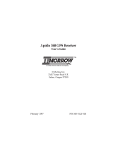
When
contacting
your dealer
or rhc
UPS Aviation
Technologies
technical services
staff,
eject the
data card
and write
down
the
information
shown on
thc label.
UPS
Aviation Technologies
APOLLO Mx20
P/N 138-0448-010
TSO
C113,
rSO
C110A
,-
Dale
of Jeppesen Nav
data
DO-1788
LEVELS C,D
oAlE
a-t''
S^ruVERSION
\
Nav
oab:
Copyrighr Jepæ""n S"no"*n.
à--:-
iloån'l*t#j:'Jå"*norosìes
rnc
---
Version
of
Mx20
software
Fpti.-l
Fpti."
r
l
Fpti""
3l
Fpt¡.n¿l
Etñ¡-l
iopt¡onol
,r,,!
I

(ìcttin.q
Startctl
Display
(ìctting
Strrtc(l
Annunciations
Advisory flags,
data
flags, anci mcssagcs appcar on thc
display
to givc
information about thc status of thc
MX20
or to providc opcrating information.
Advisory Flags
Annunciations
will
appear on thc uppcr lcfi sidc
of thc
display
to
providc
advisorics
for Traffìc, Tcrrain, and
Lightning.
Advisory information
is monitorcd and
displayed regardlcss of the sclcctcd function. Aclvisory
fìags will flash
for approximatcly
l0
seconds
whcn
thcy
fìrst appcar and thcn
turn solid
whilc thcy arc still valid.
Thc MX20 display
provides
tcxt
and graphic intòrma¡ion
to
givc a
"picturc"
of your
f'light and surroundings. The
display brightncss
may be set manuallv or allorved io
automatically
adjust to ambient light conditions.
-\t
¡h:
bottom of thc display,
labels
above the
function kevs
changc
to show thc different choiccs for each tunction ¡o
allow acccss
to commonly uscd actions. A n'pical Custom
Map function display
is shown bclo'n'. Sec pa-ee >l ¡or
dctails on display
carc.
fO Wâypo¡nt ldentif¡er Grâph¡c O¡splay
ADS-B Traíìc Distanæ to
Bear¡ng to
Destination Wpt
Destination
(TO)
Wp:
L¡ne Seleci
Ke:,.s
oata
Flags
Zoom
(Map
Scale)
Message Flag
Menu/Eniei Kei
Function Key
Photosensor
Data Ca.C
=je;:'
oâ
oA
fâ
,â
a-
a-
aâ
Jâ
Oâ
.â
a-
aA
e)
a)
a-
ê
ar)
ar)
er)
ar)
Jt-
aâ
a)
e,)
j-
.â
e-
eâ
e-
oâ
er)
e-
e-
a)
Or-
€
é
YI
rn¡,r I
4
TER
I
/
STRK
Traffic
Thc Traffic advisory flag
will
appcar on thc
lcfi
sidc
o[thc
display when
traffic
is reportcd to bc within
-f
2000 fèct of
your altitudc and 5 nm
of
your location. Thc Traffic
advisory
and Traffic functions arc only availablc
whcn
thc
ADS-B
system
is installed.
Terrain
Thc
'lcrrain
advisory flag
will
appcar on thc lcft sidc of
thc display
whcn
thc tcrrain
surfäcc
altitudc is
within
approximately
500
fcet of your
altitudc ancl
within
approximatcly two minutcs
of
f'light in any dircction.
Lightning
Thc Lightning advisory flag
will
show on thc lcft
sidc of
thc display
whcn
thc
WX500
scnds
an indication that
Iightning has
bccn dctcctcd ncar your location.
Scc thc
WX500
manual f'or dctails about ran!îc and othcr
capabilitics.
Smart
Function
Key Labels
Mount¡ng
Screw Currently Selected
Function
Thc MX20
will go into a pre-hcat mode for a short period
of'timc on start-up. During the pre-heat
mode,
thc displav
will rcmain
dark.
Thc prc-heat mode is designed to
cxtcnd thc
lifc
of thc
LCD
backlight.

Gctting Startcd
Terrain coverage
is not
available
for some
part
of the
terrain advisory coverage area.
Terrain
advlsgrlgs
may
¡ot
be
p¡ov4led.
Gctting Stanccl
Basic
Operation
Use the following
items
ro get a
basic feel for
the
operation
of the MX20.
The
basic steps
for
using any
of the
scparate
functions
of the
MX20
are:
o
Turn
the
power
on.
Adjust the
brightness
or set it to automatic.
Chcck
that all
tesrs pass
on the
Start
Up scrccn.
Press
the FN
kcy
to
view
available
functions.
Each
press
of the FN
key will
step
through
the lists
of
functions.
Press
the key
below
the function
labcl
to select
the
dcsired function.
Confirm
or enter
the currcnt
barometric
pressure
Press
the MENU/ENTER
key to
display
availablc
options.
Press
the LINE
SELECT
key next
to thc
displayed
option to choose
desired
capabilities.
Some
options
use multiple
key presses
for different
states
for the
option.
Press the
MENU/ENTER
key
again
to
extinguish
the
option
display.
.
Refer
to the Detailed
Operation
secrion
for
more
details
on each
function.
Power
On
Turn the power
rotary
knob
clockwise
past
the detent
ro
turn
the power
on. The
MX20
will progress
through a
series
of startup
screens.
The final
startup
screen
shows
System
Information
and
the results
of the
Self-Test.
Pre-Fleat
Mode
The
MX20
will
go
into a
pre-hear
modc for
a short period
of time
on start-up.
During
the pre-heat
mode,
rhe display
q'ill
remain
dark.
The pre-heat
mode is
designed
to
cxtend
the life
of the
LCD backlight.
G+-
JF
J+-
oF
eF
o,?
F
.F
]F
JF
.F
JF
€
JF
Jts
.F
.F
Jra
.F
et
.F
.F
eÐ
erra
J-
e-
o-
e,-
C-
er-
t)
f-
e-
J,-
era
eâ
e-
a)
ar'^
artl^
é
Data Flags
Data flags appear on thc left sidc of thc displa\-
to notiñ
you whcn thcre is a loss of rcportcd information.
The data
usually displayed, such
as lightning or nearby terrain.
mal
still
exist;
but
may not be displayed
for
technical
reasons.
For instancc,
when
thc amber TRA,F
data flag appears
it
means that the MX20
is
not receiving
Trailìc
information.
Traffic may bc
prcscnt,
but
will not bc displaved.
POS No
valid
position
information is available
from
the source.
Do not expect a
valid
position
representation on the
maps. The Ownship
_sy_mbol
will have an
"X"
through
it.
No valid route
(flight
plan)
is
available
from
the
external
navigation
source.
Route
(fl¡ght
plan)
information
will not
be shown
on the
maps.
ALT No
valid
altitude
information is available
from
the external source. Altitude
related functions
ì
will not
operate,
such as terrain awareness.
TD
^
E Nl^ +-^fß:^ i^l^-*a+i¡¡ i¡ ¡aaai.,¡i {¡am }ha
1
external source.
Traffic will not be displayed.
Your
position
information will not be broadcast
LT No valid
lightning detection information
is
being
received from the external source.
Strike and cell information will not be
displayed.
I
Rle
a
a
a
a
a
TRAF
¡¡o
tr"tf¡"
information is
received from the
TER
Message Flag
Mscl
Thc Mcssagc flag
will âppcar
on thc
lowcr left side of
the
function to
view
the
information about the operation
or
status of the MX20.

Gctring Startcd
Gcning Startccl
Confirm Current
Baro Correction
-\
n'indow
that displays
the current baromctric
value and
asks
vou
to veri$ the current
value or enter a new
value.
This
window
will
appear at startup
and then
every 30
minutes. Press BARO
+
to
incrcase the
value.
Press
BARO
-
to decrease
the
value.
Press
OK to confirm the
existing
values
or to
accept changes you
have
just
cntered. Press
Function Selection
Press the
FN key view the different
Functions.
The
functions are shown
above the function
"smart"
keys on
the lower part of
the display in green.
Press the
function
key under
the function
label to activate that
function.
The
labels above
thc function
key will change
to reflect the
custom
"smart"
controls
for that function.
All described
functions
may not be available
in cach installation.
Brightness
With
thc Powcr knob pulled
out, turn
the knob
in each
dircction to adjust
thc display
brightness
manually.
Manual
brightncss modc may
be selected
to adjust
the
display ftrr difficult
lighting conditions.
Push
the knob in,
and
thc brightncss is adjusted
auromarically
according
to
thc ambicnt
light.
Whcn
thc brightness
is
ser
automatically,
the display will
nor
dim
below a
pre-dcfined lcvcl.
Start Up
Screen
Thc
Start Up screen is
displaycd
while
thc MX20
goes
through its
initialization
and resring
rourines.
System
information
is shown that provides
the MX20
software
and database vcrsions.
The rcsults
of the
self test
are
shown.
A chcck mark shows
that the
test
passed.
If any
of
the Sclf-Tests
fail
(red
"x"),
contact
your dealer
or the
factory
(sce
page 52).
Confirm Current Baro
OK Baro
+
Baro
-
8¡rc[oc
t
N!
Ul) n'¡æ{001m
Jl PPtStl¡ il^VD^¡^ o^Td^Sl l
lAl
^ùú¡(¿
046, tr!'rr! 1/ lrr
$
lfl¡Ur¡¡
D^l^f¡^Stl
Glo(iMPnY I lLtSl
MFD LIMITED TO VFR
USE ONLY
srt acl ntr( ftot nf I ow
1:3
iMsc ;
Ua1l-qC,
vrn
llserectrunction
ú
g
g
g
d
ø
Cuçlqq\Lap
Ic!ç!!9n
LT
i
Lightning detect¡on
arc!

Gcming
Staned
Options
Menu
Most
functions
have
a number
of
options
available.
press
the
MENU/ENTER
key
ro
see
rhe
opdons
for
the
currenr
funcdon.
You
change
an
oprion
by
pressing
one
of
the
Line
Selection
keys
thar
are
to
the
right
of
the
displayed
option.
Many
options
have
more
than
one
choice.
press
the
same
LINE
SELECT
key
repeatedly
to
select
the
available
choices.
Some
functions
have
several
pages
of
options.
The
lower
LINE
SELECT
key will
allow y:ou
to
,
reach
the
Next
Page
when
multiple
pages
are
available.
Press
the
MENU/ENTER
key
a
second
rime
ro remove
rhe
menu
from
view
or
wait
a
few
seconds
for
the
options
to
euromarically
extinguish.
T
GeningSaned
FPL
TER
LT
ål
sr
{ I
rtisht
eran
9L- R¡or,r
"'.n
e
F \4ap
Orient
El-
36Õ/120
E
L
Sef
Barometer
EF Liohtn-¡ño
E
El-
SístemDaø
g
gf
Demo
P
PF
ffillFnìf"n",
À
"-_L
¡#ËiåËd,*,
I
z
g
a
-
o
è
Summary
MSG
MAP
IFR
$l-
,',nn,
r,"n
ål-
,,,on,
",.n
.P
I
Map
Orient
.gl-
Ma:p
Orient
õ l-
lnvert
tl- lnvèrt
ËF
I#"?*
Ët
i;;"",""
ã l-
uowR¡rwaræ
i
S
L
High
Ainrváys
É
VFR
Fl¡ght
Plan
Maþ
Orient
lnvert
Nav
Data
Tenain
Airports
VORs
NDBs
lntêrsec{ions
Airspace
LowAin¡vavs
Hiqh
Ain
,ávs
Wãter
Roads
Boundary
Traffic
Srikes
sYs
Nav
lnfo
! I
Ornshin
Svmbot
e
F
LaULon
Foimat
Ë F
Set
Ba¡o
Conection
fi -
Display
LaULon
Lines
e
¿
e
À
Test
>t
ôt
Y l-- Test Pattem 1
'g l-
Red
Test
Pattem
t
þ
Green
Test
Pattem
E
L
Blue Test
Pattem
g
White
Test
Pattem
=
g
o.

Gctting Startcd
Dctailcd
Operation
-l-his
section
describes
each
operaring function
and rhe
oprions
available
in each
function.
Each function
operares
independently.
The Funcrion
"smarr"
keys and
Line
Selection
keys are
customized
for
each function
and will
appear while
that function
is
sclected.
The functions
are
described
in the
order
that they
appear.
A description
of
each
function will
be followed
by an
explanation
of how
the function "smart"
keys
operate
for
the function
and
then
each
menu
option as
sclected
by the Line
Selection
keys.
All
described
functions
may
nor be available
in your
pariticular
installation.
See
your
Airplane
Flight Manual
supplement
for
the details
on your
individual
installation.
Detailed
Operation
This
section
describes
each
operating function
and

Dctailcd
Opcration
Messa
Lo
Function
inese I
The
Message
function
displays
information
about
the
status
of
the
MX20.
Messages
may
be logged
by either
the
MX20
internal
sysrem
or
by one
of the
external
sensors.
The
amber
MSG flag will
flash
until
the
message
is
viewed.
The
MSG
flag will
remain
in view
while
any
messages
remain
in the
message
log.
New
messages
that
have
not
been viewed
will
be
highlighted
as
bold
text.
1. Press FN
until you
see
the MSG
function
key.
2.
Press
the MSG
key.
3.
Use
the UP/DOWN
arrow
"smart"
keys
to
move
to
additional
messages,
if
more than
one
page
of messages
exlst.
4.
Press
CLEAR
to remove
the
stored
messages.
c-
J-
e-
€
J-
3-
É
É
ù-
ú-
3)
t-
ù-
J)
a¡-
c)
¿)
J)
i)
€
t-
€
J-
€
J)
r-
J)
J-
J-
¡-
t-
¡-
¡-
È-
G)
r-
c-
Èa
€
é
é
l6
-----?F
c-
c-
J'
e-
Dctailcd
Opcration
Custom
Ma
(ruAP
Function
The
Custom
Map
function
provides
a
graphic
display
of
map
features
in
relation
to the
aircraft
location
ro help
improve
your
situational
awareness.
The
custom
map
function
is unique
in
that it
has
the
ability
to
selectively
"overlay"
all
available
types
of information
onto
a
single
display.
You
can
customize
the
map
display
by
overlaying
information
selected
from
a menu
of options.
press
the
MENU
key
to
display
a list
of
options
on rhe
right
side
of
the
screen.
Press
the LINE
SELECT
key
nexr
to rhe
displayed
oprion.
Rcpeated
presses
of
the LINE
SELECT
key will
scroll
through
the
available
selections
for
each
option.
The
"smarr"
keys
at
the
bottom
of the
display
over
the
function
keys
control
the
map
scalc
by
zooming
in or
out,
moving
the
map view
around
with
the
pan
feature,
and
viewing
Info
about
rhe
currenr
destination
waypoint.
Map
Scale
The
In
and Out
function
keys
control
the
map
scale
by
zooming
in
and
out.
You
can
zoom
in
to 0.25
nm
and
zoom
out to
250
nm.
The
scale
distance
is
measured
from
the
location
of your
aircraft
symbol
ro rhe
top
of
the
screen.
The
Map
Scale
is
shown
in
the lower
left
corner
of
the screen.
The
map
oricntation
appears
above
the
map
scale
on
one
of the
three
Nav
Data
options.
F.
Zoom
Level/
Map
Oríentation
System
Unit
configured
for
Special
Terrain
System
Set
Baro
Correct¡on
o1 ol
lcrearl
luessage
007"
100r
9.sp,

I)ctrilcd
Opcration
J4
J-
e-
ê
e-
t-
ot-
a)
J'-
J'r¡^
J'-
Jr-
a'-
J-
J-
J-
J-
ar-
et-
etJ-
o,-
J-
a)
a,-
G-
Jr-
jr-
e-
or-
et-
J'-
J-
t)
J-
oâ
.â
t-
J-
or-
er-
.)
€
é
Pan
Thc
Pan
kcys
arc
used
can
scc
beyond
thc
initial
boundaries
of
thc
screcn.
Thc
PAN
lunction
key
is
onc
of
thc
"smarr"
kcys
availablc
ar
thc
bottom
of
thc
screcn.
Whcn
vou
sclcct
the
Pan
f-unction,
four
"arrow"
kcys
appear
on
the
right
side
of
the
scrcen
next
to the
LINE
SELECT
keys.
Movc
the
map
in the
to movc
the display
around
so you
desired
direction
by pressing
the
LINE
SELECT
key
next
to
the
arrow
that
shows
you want
thc map
to move.
press
the
PAN
key
again
to exit
the
Pan
mode.
While
panning,
a
grccn
rcfcrcnce
line
is
drawn
From
the
cenrer
of
the
vicwcd
arca
back
to your
currcnt
position.
Info
Prcss
thc INFO
"smart"
key to
vicw
informarion
abour
the
waypoint.
l)ctailctl
Opcration
Each
prcss
of thc INFO
kcy will
srcp
rhrough
the availablc
intt,rmation
fc¡r
thc
currcnt
dcstination
waypoint.
The
numbcr
of pagcs
dcpcnds
on rhc âmount
of information
about
thc dcstination
rvaypoint.
I
+
(-
-)
Runway
diagrams
of
airports will
orientation
as rhe
main
map
(i.e.,
DTK
Up).
bc displaycd
in thc
samc
North
Up,
Track
Up, or
007
ffim:*'is,,iiîir
%
i
APPR
lna.ooØ"^'"\ü.a"^
t9

'4
c-
e-
ê
J-
e)
J-
e)
J'-
J-
J-
J-
J)
J-
e-
J-
J-
JÐ
J)
J-
e)
e)
a)
.-
e'-
o-
J)
o-
J)
J-
C-
J-
e)
J)
e)
J-
J)
J-
J-
e-
arr^
a;a
é
20
,
Dctailcd
Opcration
Custom
Map
Menu
Option
Page
I
The
first
option
page
of the
Cusrom
Map
function
lers
you
select
options
for
the
choices
of Flighr
plan,
map
orientation,
Invert,
Nav
Data,
and
Terrain.
The
lasr
option
selection
takes
you
to rhe
nexr
page
of
options.
The
options
have
tri-state
choices
rhat
are
also
shown
visually.
When
the
option
is
clear,
the
icons
and
labels
are
nor
displayed.
When
the option
is
solid,
icons
and
labels
are
all
shown. When
the option
box
is partially
filled,
only
the
icons
are
shown.
Flight
Plan
The
Flight
Plan
option
conrrols
the
display
of
the Flight
Plan
course
line.
Pressing
thc
LINE
SELECT
key
next
to
the
Flight
Plan
option
togglcs
between
showing
or
nor
showing
the
Flight
Plan
route
line.
Map
Orientation
This
option
controls
rhe
screen
oricntation
in
reference
to
thc aircraft
symbol.
You
may
sclect
from
North
Up,
Track
Up,
Track
Up Arc,
Track
Up
360, and
Desired
Track
Up.
North
Up
sets
magnetic
north
as thc
top
of
the screen.
Track
Up
sets
the
current
track
of
the aircraft
as the
top
of
the
screen.
Track
Up
Arc
sets
rhe
currenr
track
of rhe
aircraft
and
a l20o
arc
ar the
top
of
thc
screen.
Track
Up
360
scts
the
currenr
track
of the aircrafr
at
the
top
of the
l)crrilccl
Opcration
scrccn
and
a 360"
ring with
the
aircraft
symbol
position
in
the
ccnrcr.
Desired
Track
Up
sets
thc
dcsircd
track
to
thc
next
waypoint
as
thc
top
of
thc scrccn.
prcss
thc
LINE
SELECT
kcy next
to
this
oprion
to
scroll
through
thc
options.
Invert
The
Invert
option
changes
the
display
of
tcxt and
thc
background
color.
Depending
on which
layers
are turned
on,
inverring
the
display
may
help
readability
for
thc
current
lighting
conditions.
For
instancc,
when
tcrrain
is
shown,
the
Invcrt
option
switchcs
between
white
and
black
text. Whcn
terrain
is
turned
ofl
the
Invert
option
switchcs
bctween
a
white
background
with
black
rexr
and
a
black
background
with
white
text.
Nav
Data
The
Nav
Data
option
allows
to conrrol
thc
display
of
navigation
dara
on
thc
display.
Subscqucnt
presses
of
the
LINE
SELECT
key for
this
option
providcs
choiccs
of no
nav
data,
nav
data
in
thc
corners
(waypoint,
bearing,
zoom,
and
distance),
or
full
nav
dara.
Thc
full
nav
data
option
includes
the
information
in
the four
corners
selection
plus
altitudc,
barometer
setting,
track,
and
ground
speed.

I)ct¡ilcd Opcntion
ãD
st
c-
e-
e)a
t)
.a)
3)
era
e)
e)a
e-
e-
era
e-
e-
È-
€
u)
ù)
c,a
a)
c)
€-
a)
a)
r-
Õ-
e-
3-
€-
e,a
e-
e-
e)
€ra
3-
Cra
a,a
a-
¡-
ù'a
¿
Dctrilcd Opcration
Custom
Map
Menu
Option
Page 2
The
second
option
page
of the
Custom Map
function lcts
vou
select
options for
the choiccs
of
Airports, Vors,
NDBs,
Intersections,
and Airspace.
The last
oprion
sclcction takcs
vou
to
the ncxt pagc
ofoprions.
Airports
The Airports
option allows
you ro
choosc thc levcl
of
airport
information
displayed
on rhe
Map scrccn.
You
may
sclect
the display
of airporr
icon and idcntifìcr,
icon
only, or no
information
by
each subscqucnt
press
of thc
Airport LINE
SELECT
option
keys.
VORs
'fhe
VORs
option allows
you
ro choosc
thc typc
of
VOIì
information
displaycd
on rhc
Map screcn. You
may sclcct
the display
of
VOR
icon
and idcntificr,
icon
only, or no
information
by
each subsequcnt
prcss
of thc
VOIì
LINE
SELECT
key.
NDBs
The
NDBs
option allows
you
ro choosc
thc typc of NDB
information
displayed
on rhc Map
screcn. You
may sclcct
the display
of NDB
icon and
identifìcr,
icon only,
or no
information
by
each subsequenr
press
of thc
Nl)B LINE
SELECT
kev.
Terrain
Thc
'fcrrain
option allows
you sclect
the display
of
topographical
fèaturcs. Prcssing
thc LINE
SELEGT
key
ncxt
to thc Tcrrain
option togglcs
betwecn
sectional
(absolutc),
tcrrain awarcncss
(relativc),
or
no display
of
topographical
fcaturcs.
Thc scctional
(absolute)
display
shows a
display similar to
a scctional map.
Thc terrain
awârcncss
(absolutc)
display shows
a color coded view
whcrc
thc colors rclatc to
tcrrain clcvation
relativc to
your
altituclc. For morc
information
about the
terrain
âwarencss
option, scc the Tcrrain
function
scction
on
pagc 41. Whcn
you
turn thc Terrain
fearurc off,
the
background
is either
black or white
depcnding
on your
sclcction in
thc Invert option.
Whcn
no terrain
data is
available,
the missing arcas will
be shown
in light
bluc.
'Watcr
will not
bc shown in relative
mode.
Prcss
thc Ncxt Pagc LINE
SELECT kcy
to display rhc
nexr
paec of mcnu
itcms.
\
"J
I

Dctailctl Opcration
Intersections
Thc
Intcrscctions
option allows
)¡ou
to
choose the n'pe
ot
Intcrscction
information
displayed on
thc \lap screen.
You
may sclcct
thc display
of the
Intcrsecrion icon
and
idcntifìcr,
icon
only,
or no information
bv
e
ach
subsequcnt
prcss
ofthe Inrcrsccrion
LINE
SELECT
kev.
Airspace
Thc
Airspacc
option allows
you to conrrol
the displav
ot
airspaccs.
Pressing
thc LINE
SELECT
key next to Airspace
toggles
bctween cither
the
display of airspace
boundaries
and
altitudc information,
boundaries alonc,
or no
displav
ofairspaccs.
Prcss thc Ncxt
Page LINE
SELECT
kcy to
display rhe nexr
pagc
of mcnu items.
I)crailcd
C)pcrntion
Custom
Map
Menu
Option
Page
3
The
third
oprion
pagc
of
thc
Custom
Map
function
lcts
vou
sclecr
oprions
for
the
choiccs
ol Low
Airu,ays,
High
Airu,ays,
Watcr,
Roads,
and
polirical
boundarics.
Thc
last
option
selection
takes
you
ro
rhe
next page
ofoptions.
Lcw
Airways
The
Low
Airways
oprion
allows
you
to conrrol
the
display
of
Low
Airways.
Pressing
the
LINE
SELECT
kcy
nexr
ro
Low
Airways
toggles
berween
either
thc
display
of
the
airway
and
label,
airway
alone,
or
no
display
of Low
Airways.
High
Airways
Thc
High
Airways
oprion
allows
you
ro
control
the
display
of
High
Airways.
Pressing
the
L|NE
SELECT
kcy
next
ro
High
Airways
toggles
berween
cithcr
thc
display
of
the
airway
and
label,
airway
alone,
or no
display
of
High
Airways.
Water
The Watcr
oprion
allows
you
ro conrrol
thc
display
of
rivers
and
lakes.
Prcssing
rhe
LINE
SELECT
kev
ncxt
to
\\'arcrs
toggles
bcrwccn
eithcr
thc display
or no
display
of
the
bodies
of warcr.
o1)
Jr+'
o1'
er*'
oF
erl)
ep
.F
e.)
O,-
a,)
e,)
J-
er-
orr^
erl^
arl^
er-^
er--
er-
arrl-
e.)
a.a
ê

Detailcd
Opcration
Roads
The Roads option allows you
to control
the display of
interstate and state
highways. Pressing the LINE
SELECT
key
next to Roads toggles
between either the
display or no
display ofthe road features.
Boundary
The Boundary
option allows you to select
the display
of
political
boundaries on the Map
displays.
Press the Next Page LINE
SELECT key
to display the next
page
of menu items.
Dctailcd
Operation
Custom
Map
Menu
Option
Page 4
The
fourth
oprion
page
of the
Cusrom
Map
function
lets
erla
vou
select
oprions
for
choices
of Trafhc
and
Lightning
Jp
ê
JF
%JE;:s*
H+
eF
[..:ffi
#J
#
=r4
JF
eF
Trarrìc
fl
The
Traffic
option
turns
rhe
display
of traffic
information
eP
on
or
off. Traffic
information
includes
the
location
and
-+a
identifier
of a reporting
aircraft,-
its
direction
of travel,
þ
elevation,
and
the
estimated
path
for
the
selected
time
þ
interval.
See the section
on
the
Traffic
mode for
more
þ
details
on
how traffic
information
is used.
ap
The
Traffic
function
is
not
available
in
all
software
eF
versions.
Check
your
Approved
Flight
Manual
ê
Supplement
to verifi
if this
feature
is
available.
G?
strikes
e
The
Strikes
menu
oprion
controls
the
display
of lightning
e
srike
information
if
the MX20
receives
strike
data
from
e
an
exrernal
source,
such
as the WX500.
Each reported
e
lightning
strike
is
shown
as
a red
"x"
on the
display.
aF
Strikes
are
not
shown
if the
zoom
level
is below
20
nm.
.Ð
-Ð
Press
the
Next Page
LINE
SELECT
key
to display
the next
--
Page
of
menu items'
e-
.-
.Ð
I
I
t

Dctailcd
Operation
IFR
Chart Function
The IFR
Chart function
shows
an IFR
en roure
sryle
map
for the
display. The
IFR
display shows
navigational
aid
information
and the flight plan
course
line.
The
"smarr"
keys
on the
bottom of
the screen
control
zooming
in and
out,
panning,
and the
display
of information
on the
current
TO waypoint.
The menu
of options
available
for
the IFR
mode include
Flight
Plan,
map
orienration,
Invert, and
turning
labels
on or offi
IFR
Option Page
I
The first option
page
of the IFR
Chart
function
lets you
select
options
for
the choices
of Flight
Plan, Map
Orientation,
Invert
display, Nav
Data,
and Labels.
The
last
option selection
takes you
to
the next page
ofoptions.
Flight
Plan
The
Flight Plan
option
conrrols
the display
of the
Flighr
Plan
course
line. Pres¡ing
rhe LINE
SELECT
key next
to
the
Flight Plan
option
toggles
berween
showing
and
nor
showing
the
Flight
Plan route
line.
Map
Orientation
This option
controls
the
screen orientation
in reference
ro
the
aircraft
symbol. You
may
select from
North
[-lp,
Track
Up, Track
Up Arc,
Track
Up 360, and
Desired
Track
[-Ip.
Dctailcd
Operation
.l-orth
Up
sets magnetic
north
as
the
top of
the screen.
Track
Up
sets the
current
track
of the
aircraft
as
the top
of
the
screen.
Track
Up
Arc
sers
the currenr
track
of the
aircraft
and
a l20o
arc
ar rhe
top
of the
screen.
Track
Up
360
sets
the current
track
of the
aircraft
at
the
top
of the
screen
and a
360" ring
with
the
aircraft
symbol
position
in
the
center.
Desired
Track
Up
sets
the desired
track to
the
next
waypoint
as
the
top
of the
screen.
Press
the LINE
SELECT
key
next
to
options.
Invert
option
to
scroll
through
the
The
Invert
option
changes
the
display
of text
and
the
background
color.
The
Invert
option
switches
behveen
a
white
background
with
black
text and
a black
background
with
white
text.
Nav
Data
The
Nav
Data
option
allows
you ro
conrrol
the
display
of
navigation
data on
the
Map displays.
Subsequent
presses
of the
LINE
SELECT
key
for
this option
provides
choices
of
no
nav
data, nav
data in
the corners
(waypoint,
bearing,
zoem,
and
distance),
or full
nav
data.
The
full nav
dara
option
includes
the information
in the
four
corners
selecrion
plus
altitude,
barometer
setting,
track,
and
ground
speed.
top
this
/