Page is loading ...

www.ventilation-system.com
Dix
AXIAL FAN
User’s manual
EN

2
EN
CONTENTS
Delivery set ............................................................................................................................................................................................................................................. 7
Brief description .................................................................................................................................................................................................................................. 7
Operation guidelines ....................................................................................................................................................................................................................... 7
Designation key ................................................................................................................................................................................................................................... 8
Installation............................................................................................................................................................................................................................................... 9
Electronics operation algorithm ............................................................................................................................................................................................... 11
Technical maintenance ................................................................................................................................................................................................................... 13
Troubleshooting ..................................................................................................................................................................................................................................13
Storage and transportation regulations ............................................................................................................................................................................... 14
Manufacturer’s warranty ................................................................................................................................................................................................................ 15
This user’s manual is a main operating document intended for technical, maintenance, and operating staff.
The manual contains information about purpose, technical details, operating principle, design, and installation of the Dix
unit and all its modifications.
Technical and maintenance staff must have theoretical and practical training in the field of ventilation systems and should
be able to work in accordance with workplace safety rules as well as construction norms and standards applicable in the
territory of the country.
The information in this user’s manual is correct at the time of the document’s preparation.
The Company reserves the right to modify the technical characteristics, design, or configuration of its products at any time
in order to incorporate the latest technological developments.
No part of this publication may be reproduced, stored in a retrieval system, or transmitted, in any form or by any means in any
information search system or translated into any language in any form without the prior written permission of the Company.
PLEASE READ THE USER’S MANUAL CAREFULLY PRIOR TO INSTALLING, CONNECTION TO POWER
MAINS AND OPERATING THE UNIT.
THE MANUFACTURING COMPANY SHALL NOT BE RESPONSIBLE FOR DAMAGE TO HEALTH AND
PROPERTY OF THE CUSTOMER CAUSED BY THE CUSTOMER’S VIOLATING THE USER’S MANUAL.
FOLLOW THE USER’S MANUAL REQUIREMENTS TO ENSURE DURABLE OPERATION OF THE UNIT, ITS
MECHANICAL AND ELECTRICAL RELIABILITY.
KEEP THIS USER’S MANUAL.

3
EN
All user’s manual requirements as well as the provisions of all the
applicable local and national construction, electrical, and technical
norms and standards must be observed when installing and
operating the unit.
Disconnect the unit from power supply prior to any connection,
servicing, maintenance, and repair operations.
Only qualied electricians with a work permit for electrical units
up to 1000 V are allowed for installation and maintenance. The
present user’s manual should be carefully read before beginning
works.
• Single-phase power mains must comply with the acting local
electrical norms and standards.
• Fixed electrical wiring must be equipped with an automatic circuit
breaker.
• The unit must be connected to power mains through a double pole
circuit breaker of suitable rating integrated into the fixed wiring
system with opening of contacts at all poles. The gap between the

4
EN
circuit breaker contacts at all poles must be not less than 3 mm.
• Check the unit for any visible damage of the impeller, the casing,
and the grille before starting installation. The casing internals must
be free of any foreign objects that can damage the impeller blades.
• While mounting the unit, avoid compression of the casing!
Deformation of the casing may result in motor jam and excessive
noise.
• Misuse of the unit and any unauthorized modifications are not
allowed.
• Do not expose the device to adverse atmospheric agents (rain, sun,
etc.).
• Take steps to prevent ingress of smoke, carbon monoxide, and other
combustion products into the room through open chimney flues or
other fire-protection devices. Sufficient air supply must be provided
for proper combustion and exhaust of gases through the chimney
of fuel burning equipment to prevent back drafting.
• Transported air must not contain any dust or other solid impurities,
sticky substances, or fibrous materials.

5
EN
• Do not use the unit in a hazardous or explosive environment
containing spirits, gasoline, insecticides, etc.
• For effective functioning of the unit, it is necessary to ensure an
appropriate fresh air supply into the room. Do not close or block the
intake or extract vents in order to ensure the efficient air flow.
• Do not sit on the unit and do not put objects on it.
• The unit is allowed to be used by children aged from 8 years old
and above and persons with reduced physical, sensory, or mental
capabilities or no experience and knowledge provided that they
have been given supervision or instruction regarding safe use of the
unit and understand the risks involved.
• Do not allow children to play with the unit.
• Cleaning and user maintenance shall not be made by children
without supervision.
• The information in this user’s manual was correct at the time of the
document’s preparation.
• The Company reserves the right to modify the technical

6
EN
THE PRODUCT MUST BE DISPOSED SEPARATELY AT THE END OF ITS SERVICE LIFE.
DO NOT DISPOSE THE UNIT AS UNSORTED DOMESTIC WASTE.
characteristics, design, or configuration of its products at any time in
order to incorporate the latest technological developments.
• No part of this publication may be reproduced, stored in a retrieval
system, or transmitted, in any form or by any means in any
information search system or translated into any language in any
form without the prior written permission of the Company.
WARNING! Similar to the use of any other household electrical
appliances when operating this fan, the following basic rules
must be followed:
• Never touch the fan with wet or damp hands.
• Never touch the fan when barefoot.

7
EN
DELIVERY SET
Fan — 1 pc.
Screws and dowels — 4 pcs.
Plastic screwdriver (only for the models with a timer) — 1 pc.
User’s manual — 1 pc.
Packing box — 1 pc.
BRIEF DESCRIPTION
The unit described herein is an axial fan for exhaust ventilation of small and medium-sized utility spaces.
The fan is designed for connection to Ø 100 or 150 mm air ducts, depending on the model.
OPERATION GUIDELINES
The fan is rated for connection to single-phase AC power mains.
Power mains parameters are stated on the unit packaging and/or the label on the unit casing.
Ingress protection rating against access to hazardous parts and water ingress is IP44.
WARNING! IP is indicated for an assembled unit.
The fan is rated for operation at ambient temperatures ranging from +1 °C to +40 °C.
WARNING! Do not operate the fan outside the specied temperature range.
The unit is rated as the Class II (220-240 V, 50 Hz/220 V, 60 Hz) or the Class III (12 V/50 Hz) electrical appliance and requires
no grounding.

8
EN
DESIGNATION KEY
Dix 100 - Х Х Х
Unit voltage:
_: 220-240 V/50 Hz
220 V/60 Hz: supply voltage 220 V, power frequency 60 Hz
Additional options:
L: motor on ball bearings
V: pull cord switch
T: turn-off delay timer
T1: turn-on and turn-off delay timer
VT: pull cord switch and turn-off delay timer
TH: humidity sensor
VTH: pull cord switch and humidity sensor
Motor modication:
_: basic motor
12: low voltage motor 12 V/50 Hz
Duo: two-speed motor
Outlet duct diameter [mm]
100/150
Fan series

9
EN
INSTALLATION
The fan is designed for wall mounting (with motors on sliding and ball bearings) or ceiling mounting (only with motors on
ball bearings, option L) and can be used to discharge air directly outside through a round duct or through a duct system.
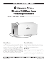
In case of installation through a duct system, select the duct cross section in accordance with the fan size (Fig. 1).
1. When installing the fan with direct air discharge outside through the wall, be sure to install a ventilation grille with louvre
shutters or a ventilation hood on the outside to prevent rainfall, snow, leaves, branches, etc. from entering the duct.
To reduce the risk of condensate forming in the duct, the space between the hole in the wall and the duct must be insulated.
Install the air duct with the minimum slope of 1...2° downwards to the outer wall side for condensate removal (Fig 2).
2. The duct system should not exceed 5 meters and have more than two bends.
3. During ceiling installation, vertical air discharge upwards is not allowed even if there is a protective outer hood on the roof.
For ceiling mounting and air discharge to the roof, the duct system must include a condensate drain (Fig. 3).
A condensate drain is not included in the delivery set of the fan and can be ordered separately.
Check the fan for any visible damages of the impeller, the casing and the grille before starting installation. The casing internals
must be free of any foreign objects which can damage the impeller blades.
While mounting the unit, avoid compression of the casing! Deformation of the casing may result in the motor jam and
excessive noise. Mount the fan on the wall or ceiling using four dowels with screws (included in the delivery set).
Dowels and screws are designed for concrete and brick walls. If the walls are made of the other material (drywall, wood,
etc.), use the fasteners appropriate for these materials to fasten the fan (not supplied with the fan and must be purchased
separately).
WARNING! When the fan is equipped with a non-return valve, operation of the fan without the valve is prohibited.

10
EN
The fan mounting sequence is shown in Fig. 4-12.
The fan wiring diagrams are shown in Fig. 13-18.
Terminal designations on wiring diagrams:
L — line/~12 V S1 — external switch
N — neutral/~12 V QF — double pole circuit breaker
S — timer control line
WARNING! The fans rated for 12 V power voltage (stated on the packing box and on the fan casing) connect
to ~12 V power mains only!
WARNING! The power cable may only be laid through the hole in the casing provided by the manufacturer (Fig. 13).
Laying the power cable through a manually drilled hole will not be the liability of the manufacturer and will void
the warranty. The wires must be stripped of insulation by a maximum of 8 mm (Fig. 13).
After installation, pass this User’s manual to the end user for reading.

11
EN
ELECTRONICS OPERATION ALGORITHM
The fan with the timer (T) activates upon control voltage application to the S input terminal by the S1 external switch (e.g.
indoor light switch). After the control voltage is off, the fan continues to operate within the time set by the timer ranging
from 2 to 30 minutes. For the VT model, the fan is turned on/off with an internal cord switch.
The fan with the timer (T1) – when the control voltage is applied to the S input by an external switch S1 (for example,
switching on the room light), the turn-on delay timer is activated, and the fan blades do not rotate. The value of the turn-on
delay time is adjustable in the range from 0 to 2 minutes. Select the adjustment range using the jumper on the timer board.
After some turn-on delay time has elapsed, the fan turns on and the blades start rotating. After the control voltage is off, the
fan continues to operate within the time set by the turn-off delay timer adjustable from 2 to 30 minutes.
The two-speed fan with the timer (Duo T1) operates at Speed 1 when the control voltage is applied to the S input with
the S1 external switch. The turn-on delay timer turns on, and the fan blades do not rotate. The value of the turn-on delay
time is adjustable in the range from 0 to 2 minutes. After some turn-on delay time has elapsed, the fan switches to Speed 2.
After disconnecting the control voltage, the fan runs for a time set by the turn-off delay timer (from 2 to 30 minutes), and
switches to the first speed.
The fan with the timer and the humidity sensor (TH) – the fan starts after the control voltage is supplied to the input
terminal S or if indoor humidity level H exceeds the set point adjustable from ~60 % to ~90 %.
After the control voltage is off or the humidity level has decreased, the fan will keep running within the time set by the turn-
off delay timer ranging from 2 to 30 minutes.
The two-speed fan with the timer and the humidity sensor (Duo TH) switches to Speed 2 as the indoor humidity
exceeds set level (adjustable from 60 % up to 90 % ). As the indoor humidity level drops down to the set value, the fan keeps
operating for 5 minutes and then switches to Speed 1. The fan can be controlled manually, for example, by a light switch.
When the control voltage is applied, the turn-on delay timer is activated for 45 seconds and the fan switches to the second
speed. After disconnecting the control voltage, the fan runs for a time set by the turn-off delay timer (from 2 to 30 minutes),
and switches to the first speed. To set the maximum humidity set point, set the potentiometer to H
max
position (90 %).

12
EN
— To adjust the fan turn-on delay time, turn the control knob T
on
clockwise to increase and counter-clockwise to
decrease the turn-on delay time set point, adjustable from 0 up to 2 minutes.
— To adjust the fan turn-off delay time, turn the control knob T
o
clockwise to increase and counter-clockwise to
decrease the turn-off delay time set point, adjustable from 2 up to 30 minutes.
— To adjust the humidity set point, turn the control knob H clockwise to increase and counter-clockwise to decrease the
humidity sensor set point, adjustable from 60 % up to 90 %.
The fan delivery set includes a specially designed plastic
screwdriver for fan settings adjustments.
Use it to change the turn-on and turn-off delay time and
the humidity set point.
H
60%
90%
T
o
2 min
30 min
T
on
0 min
2 min
for T1
for TH/VTH
DO NOT USE A METAL SCREWDRIVER, KNIFE, ETC. FOR ADJUSTMENT
OPERATIONS NOT TO DAMAGE THE CIRCUIT BOARD.

13
EN
TECHNICAL MAINTENANCE
The fan maintenance periodicity is at least once per 6 months.
Maintenance steps:
• Disconnect the fan from power supply and make sure electricity has been turned off (Fig. 19).
• Remove the front and the decorative panels, wipe the fan with a dry cloth or a brush (Fig. 20).
• Clean the front panel under running water (Fig. 21).
• Wipe the fan surfaces dry.
• Cover the fan with the front panel.
• Connect power supply to the fan (Fig. 22).
WARNING! Do not allow water or liquid come into contact with electric components!
TROUBLESHOOTING
Problem Possible reasons Troubleshooting
When the unit is connected to power
mains, the fan does not rotate and
does not respond to any controls.
No power supply.
Make sure the power supply line
is connected correctly, otherwise
troubleshoot the connection error.
Internal connection fault. Contact the Seller.
Low air flow. The ventilation system is clogged. Clean the ventilation system.
Increased noise, vibration.
The impeller is clogged. Clean the impeller.
The fan is not secured well or is not
mounted properly.
Troubleshoot the installation error.
The ventilation system is clogged. Clean the ventilation system.

14
EN
STORAGE AND TRANSPORTATION REGULATIONS
• Store the unit in the manufacturer’s original packaging box in a dry closed ventilated premise with temperature range
from +5 ˚С to +40 ˚С and relative humidity up to 70 %.
• Storage environment must not contain aggressive vapors and chemical mixtures provoking corrosion, insulation, and
sealing deformation.
• Use suitable hoist machinery for handling and storage operations to prevent possible damage to the unit.
• Follow the handling requirements applicable for the particular type of cargo.
• The unit can be carried in the original packaging by any mode of transport provided proper protection against
precipitation and mechanical damage. The unit must be transported only in the working position.
• Avoid sharp blows, scratches, or rough handling during loading and unloading.
• Prior to the initial power-up after transportation at low temperatures, allow the unit to warm up at operating
temperature for at least 3-4 hours.

15
EN
MANUFACTURER’S WARRANTY
The product is in compliance with EU norms and standards on low voltage guidelines and electromagnetic compatibility.
We hereby declare that the product complies with the provisions of Electromagnetic Compatibility (EMC) Directive 2014/30/
EU of the European Parliament and of the Council, Low Voltage Directive (LVD) 2014/35/EU of the European Parliament and
of the Council and CE-marking Council Directive 93/68/EEC. This certificate is issued following test carried out on samples
of the product referred to above.
The manufacturer hereby warrants normal operation of the unit for 60 months after the retail sale date provided the user's
observance of the transportation, storage, installation, and operation regulations. Should any malfunctions occur in the
course of the unit operation through the Manufacturer's fault during the guaranteed period of operation, the user is entitled
to get all the faults eliminated by the manufacturer by means of warranty repair at the factory free of charge. The warranty
repair includes work specific to elimination of faults in the unit operation to ensure its intended use by the user within the
guaranteed period of operation. The faults are eliminated by means of replacement or repair of the unit components or a
specific part of such unit component.
The warranty repair does not include:
• routine technical maintenance
• unit installation/dismantling
• unit setup
To benefit from warranty repair, the user must provide the unit, the user's manual with the purchase date stamp, and the
payment paperwork certifying the purchase. The unit model must comply with the one stated in the user’s manual. Contact
the Seller for warranty service.
The manufacturer’s warranty does not apply to the following cases:
• User’s failure to submit the unit with the entire delivery package as stated in the user’s manual including submission
with missing component parts previously dismounted by the user.
• Mismatch of the unit model and the brand name with the information stated on the unit packaging and in the user's
manual.
• User’s failure to ensure timely technical maintenance of the unit.
• External damage to the unit casing (excluding external modifications as required for installation) and internal

16
EN
components caused by the user.
• Redesign or engineering changes to the unit.
• Replacement and use of any assemblies, parts and components not approved by the manufacturer.
• Unit misuse.
• Violation of the unit installation regulations by the user.
• Violation of the unit control regulations by the user.
• Unit connection to power mains with a voltage different from the one stated in the user's manual.
• Unit breakdown due to voltage surges in power mains.
• Discretionary repair of the unit by the user.
• Unit repair by any persons without the manufacturer’s authorization.
• Expiration of the unit warranty period.
• Violation of the unit transportation regulations by the user.
• Violation of the unit storage regulations by the user.
• Wrongful actions against the unit committed by third parties.
• Unit breakdown due to circumstances of insuperable force (fire, flood, earthquake, war, hostilities of any kind,
blockades).
• Missing seals if provided by the user’s manual.
• Failure to submit the user’s manual with the unit purchase date stamp.
• Missing payment paperwork certifying the unit purchase.
FOLLOWING THE REGULATIONS STIPULATED HEREIN WILL ENSURE A LONG AND TROUBLE-FREE
OPERATION OF THE UNIT.
USER’S WARRANTY CLAIMS SHALL BE SUBJECT TO REVIEW ONLY UPON PRESENTATION OF THE
UNIT, THE PAYMENT DOCUMENT AND THE USER’S MANUAL WITH THE PURCHASE DATE STAMP.

17
EN
B
ø D
L
1.
D [mm] B [mm] L [mm]
Dix 100 100 150 102
Dix 150 150 206 123
1
0
...2
0
2.
3.

18
EN
QF
L N
4. 5. 6.
7. 8. 9.
10. 11. 12.

19
EN
13.
S
N
QF
L
N
L
S1
S
N
QF
L
N
L
S
N
QF
L
N
L
S1
Fan does not run
Contact of S1 switch or pull
cord switch is CLOSED
Fan runs
Contact of S1 switch or pull
cord switch is OPENED
Activation of turn-off
delay timer (2-30 minutes)
... 100/150 ... 100/150 Т ... 100/150 VТ
Fan does not run
Contact of S1 switch or pull
cord switch is CLOSED
Fan runs
Contact of S1 switch or pull
cord switch is OPENED
Activation of turn-off
delay timer (2-30 minutes)
8 mm
max.

20
EN
14.
S
N
QF
L
N
L
S1
Fan does not run
Contact of S1 switch or
pull cord switch is CLOSED
Switch is deactivated
during countdown
of turn-on delay timer
Fan runs
Contact of S1 switch or pull
cord switch is OPENED
Activation of turn-off
delay timer (2-30 minutes)
YesNo
... 100/150 Т1
Fan does not run
Contact of S1 switch or
pull cord switch is CLOSED
Switch is deactivated
during countdown
of turn-on delay timer
Fan runs
Contact of S1 switch or pull
cord switch is OPENED
Activation of turn-off
delay timer (2-30 minutes)
YesNo
Activation of turn-on
delay timer (0-2 minutes)
/