Miller HYDRACOOL 1 CE Owner's manual
- Category
- Welding System
- Type
- Owner's manual
This manual is also suitable for

Hydracool 1
Hydracool 2
Processes
Description
TIG (GTAW) Welding
MIG (GMAW) Welding
OM-254 203A 2011−08
File: TIG (GTAW)
CE

Thank you and congratulations on choosing Miller. Now you can get the
job done and get it done right. We know you don’t have time to do it any
other way.
That’s why when Niels Miller first started building arc welders in 1929,
he made sure his products offered long-lasting value and superior quality.
Like you, his customers couldn’t afford anything less. Miller products had
to be more than the best they could be. They had to be the best you could
buy.
Today, the people that build and sell Miller products continue the
tradition. They’re just as committed to providing equipment and service
that meets the high standards of quality and value established in 1929.
This Owner’s Manual is designed to help you get the most out of your
Miller products. Please take time to read the Safety precautions. They will
help you protect yourself against potential hazards on the worksite. We’ve
made installation and operation quick and easy. With Miller you can
count on years of reliable service with proper maintenance. And if for
some reason the unit needs repair, there’s a Troubleshooting section that
will help you figure out what the problem is. The parts list will then help
you to decide which exact part you may need to fix the problem.
Warranty and service information for your particular model are also
provided.
Miller Electric manufactures a full line of
welders and welding related equipment. For
information on other quality Miller products, contact your local Miller
distributor to receive the latest full line catalog or individual catalog sheets.
Working as hard as you do
− every power source from
Miller is backed by the most
hassle-free warranty in the
business.
From Miller to You

TABLE OF CONTENTS
SECTION 1 − SAFETY PRECAUTIONS - READ BEFORE USING 1.................................
1-1. Symbol Usage 1.......................................................................
1-2. Arc Welding Hazards 1.................................................................
1-3. Additional Symbols For Installation, Operation, And Maintenance 3.............................
1-4. California Proposition 65 Warnings 4......................................................
1-5. Principal Safety Standards 4.............................................................
1-6. EMF Information 4.....................................................................
SECTION 2 − DEFINITIONS 5..................................................................
2-1. Warning Label Definitions (For Wordless Labels) 5..........................................
2-2. WEEE Label (For Products Sold Within The EU) 6..........................................
2-3. Symbols And Definitions 6...............................................................
SECTION 3 − SPECIFICATIONS 7..............................................................
3-1. Important Information Regarding CE Products (Sold Within The EU) 7..........................
3-2. Serial Number And Rating Label Location 7................................................
3-3. Specifications* 7.......................................................................
SECTION 4 − INSTALLATION 8................................................................
4-1. Selecting a Location 8..................................................................
SECTION 5 − OPERATION 9...................................................................
5-1. Control Panel Hydracool 1 9.............................................................
5-2. Control Panel Hydracool 2 9.............................................................
SECTION 6 − MAINTENANCE & TROUBLESHOOTING 10.........................................
6-1. Routine Maintenance 10.................................................................
6-2. Troubleshooting 10......................................................................
SECTION 7 − ELECTRICAL DIAGRAM 11........................................................
SECTION 8 − PARTS LIST 12...................................................................
WARRANTY

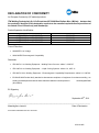
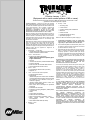
DECLARATION OF CONFORMITY
for European Community (CE marked) products.
ITW Welding Products Italy S.r.l Via Privata Iseo 6/E, 20098 San Giuliano M.se, (MI) Italy declares that
the product(s) identified in this declaration conform to the essential requirements and provisions of
the stated Council Directive(s) and Standard(s).
Product/Apparatus Identification:
Product Stock Number
HYDRACOOL 1 V.115 50/60HZ 028042103
HYDRACOOL 1 V.230 50/60HZ 028042104
HYDRACOOL 2 V.115 50/60HZ 028042105
HYDRACOOL 2 V.230 50/60HZ 028042106
Council Directives:
2006/95/EC Low Voltage
2004/108/EC Electromagnetic Compatibility
Standards:
IEC 609741 Arc Welding Equipment Welding Power Sources: edition 3, 200507.
IEC 609742 Arc Welding Equipment – Liquid Cooling Systems: edition 2.0, 200711.
IEC 6097410 Arc Welding Equipment Electromagnetic Compatibility Requirements: edition 2.0, 200708.
EN 50445:2008 Product family standard to demonstrate compliance of equipment for resistance welding, arc
welding and allied processes with the basic restrictions related to human exposure to electromagnetic fields
(0Hz300Hz)
EU Signatory:
September 30
th
, 2011
___________________________________________________________________________________
Massimigliano Lavarini Date of Declaration
ELECTRONIC ENGINEER R&D TECH. SUPPORT
956 142 902

OM-254 203 Page 1
SECTION 1 − SAFETY PRECAUTIONS - READ BEFORE USING
som 2011−01
7
Protect yourself and others from injury — read and follow these precautions.
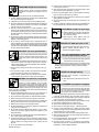
1-1. Symbol Usage
DANGER! − Indicates a hazardous situation which, if
not avoided, will result in death or serious injury. The
possible hazards are shown in the adjoining symbols
or explained in the text.
Indicates a hazardous situation which, if not avoided,
could result in death or serious injury. The possible
hazards are shown in the adjoining symbols or ex-
plained in the text.
NOTICE − Indicates statements not related to personal injury.
Indicates special instructions.
This group of symbols means Warning! Watch Out! ELECTRIC
SHOCK, MOVING PARTS, and HOT PARTS hazards. Consult sym-
bols and related instructions below for necessary actions to avoid the
hazards.
1-2. Arc Welding Hazards
The symbols shown below are used throughout this manual
to call attention to and identify possible hazards. When you
see the symbol, watch out, and follow the related instructions
to avoid the hazard. The safety information given below is
only a summary of the more complete safety information
found in the Safety Standards listed in Section 1-5. Read and
follow all Safety Standards.
Only qualified persons should install, operate, maintain, and
repair this unit.
During operation, keep everybody, especially children, away.
ELECTRIC SHOCK can kill.
Touching live electrical parts can cause fatal shocks
or severe burns. The electrode and work circuit is
electrically live whenever the output is on. The input
power circuit and machine internal circuits are also
live when power is on. In semiautomatic or automatic
wire welding, the wire, wire reel, drive roll housing,
and all metal parts touching the welding wire are
electrically live. Incorrectly installed or improperly
grounded equipment is a hazard.
Do not touch live electrical parts.
Wear dry, hole-free insulating gloves and body protection.
Insulate yourself from work and ground using dry insulating mats
or covers big enough to prevent any physical contact with the work
or ground.
Do not use AC output in damp areas, if movement is confined, or if
there is a danger of falling.
Use AC output ONLY if required for the welding process.
If AC output is required, use remote output control if present on
unit.
Additional safety precautions are required when any of the follow-
ing electrically hazardous conditions are present: in damp
locations or while wearing wet clothing; on metal structures such
as floors, gratings, or scaffolds; when in cramped positions such
as sitting, kneeling, or lying; or when there is a high risk of unavoid-
able or accidental contact with the workpiece or ground. For these
conditions, use the following equipment in order presented: 1) a
semiautomatic DC constant voltage (wire) welder, 2) a DC manual
(stick) welder, or 3) an AC welder with reduced open-circuit volt-
age. In most situations, use of a DC, constant voltage wire welder
is recommended. And, do not work alone!
Disconnect input power or stop engine before installing or
servicing this equipment. Lockout/tagout input power according to
OSHA 29 CFR 1910.147 (see Safety Standards).
Properly install and ground this equipment according to its
Owner’s Manual and national, state, and local codes.
Always verify the supply ground − check and be sure that input
power cord ground wire is properly connected to ground terminal in
disconnect box or that cord plug is connected to a properly
grounded receptacle outlet.
When making input connections, attach proper grounding conduc-
tor first − double-check connections.
Keep cords dry, free of oil and grease, and protected from hot metal
and sparks.
Frequently inspect input power cord for damage or bare wiring −
replace cord immediately if damaged − bare wiring can kill.
Turn off all equipment when not in use.
Do not use worn, damaged, undersized, or poorly spliced cables.
Do not drape cables over your body.
If earth grounding of the workpiece is required, ground it directly
with a separate cable.
Do not touch electrode if you are in contact with the work, ground,
or another electrode from a different machine.
Do not touch electrode holders connected to two welding ma-
chines at the same time since double open-circuit voltage will be
present.
Use only well-maintained equipment. Repair or replace damaged
parts at once. Maintain unit according to manual.
Wear a safety harness if working above floor level.
Keep all panels and covers securely in place.
Clamp work cable with good metal-to-metal contact to workpiece
or worktable as near the weld as practical.
Insulate work clamp when not connected to workpiece to prevent
contact with any metal object.
Do not connect more than one electrode or work cable to any
single weld output terminal.
SIGNIFICANT DC VOLTAGE exists in inverter weld-
ing power sources AFTER removal of input power.
Turn Off inverter, disconnect input power, and discharge input
capacitors according to instructions in Maintenance Section
before touching any parts.
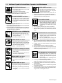
HOT PARTS can burn.
Do not touch hot parts bare handed.
Allow cooling period before working on equip-
ment.
To handle hot parts, use proper tools and/or
wear heavy, insulated welding gloves and
clothing to prevent burns.

OM-254 203 Page 2
Welding produces fumes and gases. Breathing
these fumes and gases can be hazardous to your
health.
FUMES AND GASES can be hazardous.
Keep your head out of the fumes. Do not breathe the fumes.
If inside, ventilate the area and/or use local forced ventilation at the
arc to remove welding fumes and gases.
If ventilation is poor, wear an approved air-supplied respirator.
Read and understand the Material Safety Data Sheets (MSDSs)
and the manufacturer’s instructions for metals, consumables,
coatings, cleaners, and degreasers.
Work in a confined space only if it is well ventilated, or while
wearing an air-supplied respirator. Always have a trained watch-
person nearby. Welding fumes and gases can displace air and
lower the oxygen level causing injury or death. Be sure the breath-
ing air is safe.
Do not weld in locations near degreasing, cleaning, or spraying op-
erations. The heat and rays of the arc can react with vapors to form
highly toxic and irritating gases.
Do not weld on coated metals, such as galvanized, lead, or
cadmium plated steel, unless the coating is removed from the weld
area, the area is well ventilated, and while wearing an air-supplied
respirator. The coatings and any metals containing these elements
can give off toxic fumes if welded.
Arc rays from the welding process produce intense
visible and invisible (ultraviolet and infrared) rays
that can burn eyes and skin. Sparks fly off from the
weld.
Wear an approved welding helmet fitted with a proper shade of
filter lenses to protect your face and eyes from arc rays and
sparks when welding or watching (see ANSI Z49.1 and Z87.1
listed in Safety Standards).
Wear approved safety glasses with side shields under your
helmet.
Use protective screens or barriers to protect others from flash,
glare and sparks; warn others not to watch the arc.
Wear protective clothing made from durable, flame-resistant
material (leather, heavy cotton, or wool) and foot protection.
ARC RAYS can burn eyes and skin.
Welding on closed containers, such as tanks,
drums, or pipes, can cause them to blow up. Sparks
can fly off from the welding arc. The flying sparks, hot
workpiece, and hot equipment can cause fires and
burns. Accidental contact of electrode to metal objects can cause
sparks, explosion, overheating, or fire. Check and be sure the area is
safe before doing any welding.
WELDING can cause fire or explosion.
Remove all flammables within 35 ft (10.7 m) of the welding arc. If
this is not possible, tightly cover them with approved covers.
Do not weld where flying sparks can strike flammable material.
Protect yourself and others from flying sparks and hot metal.
Be alert that welding sparks and hot materials from welding can
easily go through small cracks and openings to adjacent areas.
Watch for fire, and keep a fire extinguisher nearby.
Be aware that welding on a ceiling, floor, bulkhead, or partition can
cause fire on the hidden side.
Do not weld on closed containers such as tanks, drums, or pipes,
unless they are properly prepared according to AWS F4.1 (see
Safety Standards).
Do not weld where the atmosphere may contain flammable dust,
gas, or liquid vapors (such as gasoline).
Connect work cable to the work as close to the welding area as
practical to prevent welding current from traveling long, possibly
unknown paths and causing electric shock, sparks, and fire
hazards.
Do not use welder to thaw frozen pipes.
Remove stick electrode from holder or cut off welding wire at
contact tip when not in use.
Wear oil-free protective garments such as leather gloves, heavy
shirt, cuffless trousers, high shoes, and a cap.
Remove any combustibles, such as a butane lighter or matches,
from your person before doing any welding.
After completion of work, inspect area to ensure it is free of sparks,
glowing embers, and flames.
Use only correct fuses or circuit breakers. Do not oversize or by-
pass them.
Follow requirements in OSHA 1910.252 (a) (2) (iv) and NFPA 51B
for hot work and have a fire watcher and extinguisher nearby.
FLYING METAL or DIRT can injure eyes.
Welding, chipping, wire brushing, and grinding
cause sparks and flying metal. As welds cool,
they can throw off slag.
Wear approved safety glasses with side
shields even under your welding helmet.
BUILDUP OF GAS can injure or kill.
Shut off compressed gas supply when not in use.
Always ventilate confined spaces or use
approved air-supplied respirator.
ELECTRIC AND MAGNETIC FIELDS (EMF
)
can affect Implanted Medical Devices.
Wearers of Pacemakers and other Implanted
Medical Devices should keep away.
Implanted Medical Device wearers should consult their doctor
and the device manufacturer before going near arc welding, spot
welding, gouging, plasma arc cutting, or induction heating
operations.
NOISE can damage hearing.
Noise from some processes or equipment can
damage hearing.
Wear approved ear protection if noise level is
high.
Compressed gas cylinders contain gas under high
pressure. If damaged, a cylinder can explode. Since
gas cylinders are normally part of the welding
process, be sure to treat them carefully.
CYLINDERS can explode if damaged.
Protect compressed gas cylinders from excessive heat, mechani-
cal shocks, physical damage, slag, open flames, sparks, and arcs.
Install cylinders in an upright position by securing to a stationary
support or cylinder rack to prevent falling or tipping.
Keep cylinders away from any welding or other electrical circuits.
Never drape a welding torch over a gas cylinder.
Never allow a welding electrode to touch any cylinder.
Never weld on a pressurized cylinder − explosion will result.
Use only correct compressed gas cylinders, regulators, hoses,
and fittings designed for the specific application; maintain them
and associated parts in good condition.
Turn face away from valve outlet when opening cylinder valve.
Keep protective cap in place over valve except when cylinder is in
use or connected for use.
Use the right equipment, correct procedures, and sufficient num-
ber of persons to lift and move cylinders.
Read and follow instructions on compressed gas cylinders,
associated equipment, and Compressed Gas Association (CGA)
publication P-1 listed in Safety Standards.

OM-254 203 Page 3
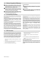
1-3. Additional Symbols For Installation, Operation, And Maintenance
FIRE OR EXPLOSION hazard.
Do not install or place unit on, over, or near
combustible surfaces.
Do not install unit near flammables.
Do not overload building wiring − be sure power supply system is
properly sized, rated, and protected to handle this unit.
FALLING EQUIPMENT can injure.
Use lifting eye to lift unit only, NOT running
gear, gas cylinders, or any other accessories.
Use equipment of adequate capacity to lift and
support unit.
If using lift forks to move unit, be sure forks are long enough to
extend beyond opposite side of unit.
Keep equipment (cables and cords) away from moving vehicles
when working from an aerial location.
Follow the guidelines in the Applications Manual for the Revised
NIOSH Lifting Equation (Publication No. 94−110) when manu-
ally lifting heavy parts or equipment.
OVERUSE can cause OVERHEATING
Allow cooling period; follow rated duty cycle.
Reduce current or reduce duty cycle before
starting to weld again.
Do not block or filter airflow to unit.
FLYING SPARKS can injure.
Wear a face shield to protect eyes and face.
Shape tungsten electrode only on grinder with
proper guards in a safe location wearing proper
face, hand, and body protection.
Sparks can cause fires — keep flammables away.
STATIC (ESD) can damage PC boards.
Put on grounded wrist strap BEFORE handling
boards or parts.
Use proper static-proof bags and boxes to
store, move, or ship PC boards.
MOVING PARTS can injure.
Keep away from moving parts.
Keep away from pinch points such as drive
rolls.
WELDING WIRE can injure.
Do not press gun trigger until instructed to do
so.
Do not point gun toward any part of the body,
other people, or any metal when threading
welding wire.
MOVING PARTS can injure.
Keep away from moving parts such as fans.
Keep all doors, panels, covers, and guards
closed and securely in place.
Have only qualified persons remove doors, panels, covers, or
guards for maintenance and troubleshooting as necessary.
Reinstall doors, panels, covers, or guards when maintenance is
finished and before reconnecting input power.
READ INSTRUCTIONS.
Read and follow all labels and the Owner’s
Manual carefully before installing, operating, or
servicing unit. Read the safety information at
the beginning of the manual and in each
section.
Use only genuine replacement parts from the manufacturer.
Perform maintenance and service according to the Owner’s
Manuals, industry standards, and national, state, and local
codes.
H.F. RADIATION can cause interference.
High-frequency (H.F.) can interfere with radio
navigation, safety services, computers, and
communications equipment.
Have only qualified persons familiar with
electronic equipment perform this installation.
The user is responsible for having a qualified electrician prompt-
ly correct any interference problem resulting from the installa-
tion.
If notified by the FCC about interference, stop using the
equipment at once.
Have the installation regularly checked and maintained.
Keep high-frequency source doors and panels tightly shut, keep
spark gaps at correct setting, and use grounding and shielding to
minimize the possibility of interference.
ARC WELDING can cause interference.
Electromagnetic energy can interfere with
sensitive electronic equipment such as
computers and computer-driven equipment
such as robots.
Be sure all equipment in the welding area is
electromagnetically compatible.
To reduce possible interference, keep weld cables as short as
possible, close together, and down low, such as on the floor.
Locate welding operation 100 meters from any sensitive elec-
tronic equipment.
Be sure this welding machine is installed and grounded
according to this manual.
If interference still occurs, the user must take extra measures
such as moving the welding machine, using shielded cables,
using line filters, or shielding the work area.

OM-254 203 Page 4
1-4. California Proposition 65 Warnings
Welding or cutting equipment produces fumes or gases
which contain chemicals known to the State of California to
cause birth defects and, in some cases, cancer. (California
Health & Safety Code Section 25249.5 et seq.)
Battery posts, terminals and related accessories contain lead
and lead compounds, chemicals known to the State of
California to cause cancer and birth defects or other
reproductive harm. Wash hands after handling.
This product contains chemicals, including lead, known to
the state of California to cause cancer, birth defects, or other
reproductive harm. Wash hands after use.
For Gasoline Engines:
Engine exhaust contains chemicals known to the State of
California to cause cancer, birth defects, or other reproduc-
tive harm.
For Diesel Engines:
Diesel engine exhaust and some of its constituents are
known to the State of California to cause cancer, birth
defects, and other reproductive harm.
1-5. Principal Safety Standards
Safety in Welding, Cutting, and Allied Processes, ANSI Standard Z49.1,
from Global Engineering Documents (phone: 1-877-413-5184, website:
www.global.ihs.com).
Safe Practices for the Preparation of Containers and Piping for Welding
and Cutting, American Welding Society Standard AWS F4.1, from Glob-
al Engineering Documents (phone: 1-877-413-5184, website:
www.global.ihs.com).
National Electrical Code, NFPA Standard 70, from National Fire Protec-
tion Association, Quincy, MA 02269 (phone: 1-800-344-3555, website:
www.nfpa.org and www. sparky.org).
Safe Handling of Compressed Gases in Cylinders, CGA Pamphlet P-1,
from Compressed Gas Association, 4221 Walney Road, 5th Floor,
Chantilly, VA 20151 (phone: 703-788-2700, website:www.cganet.com).
Safety in Welding, Cutting, and Allied Processes, CSA Standard
W117.2, from Canadian Standards Association, Standards Sales, 5060
Spectrum Way, Suite 100, Ontario, Canada L4W 5NS (phone:
800-463-6727, website: www.csa-international.org).
Safe Practice For Occupational And Educational Eye And Face Protec-
tion, ANSI Standard Z87.1, from American National Standards Institute,
25 West 43rd Street, New York, NY 10036 (phone: 212-642-4900, web-
site: www.ansi.org).
Standard for Fire Prevention During Welding, Cutting, and Other Hot
Work, NFPA Standard 51B, from National Fire Protection Association,
Quincy, MA 02269 (phone: 1-800-344-3555, website: www.nfpa.org.
OSHA, Occupational Safety and Health Standards for General Indus-
try, Title 29, Code of Federal Regulations (CFR), Part 1910, Subpart Q,
and Part 1926, Subpart J, from U.S. Government Printing Office, Super-
intendent of Documents, P.O. Box 371954, Pittsburgh, PA 15250-7954
(phone: 1-866-512-1800) (there are 10 OSHA Regional Offices—
phone for Region 5, Chicago, is 312-353-2220, website:
www.osha.gov).
U.S. Consumer Product Safety Commission (CPSC), 4330 East West
Highway, Bethesda, MD 20814 (phone: 301-504-7923, website:
www.cpsc.gov).
Applications Manual for the Revised NIOSH Lifting Equation, The Na-
tional Institute for Occupational Safety and Health (NIOSH), 1600
Clifton Rd, Atlanta, GA 30333 (phone: 1-800-232-4636, website:
www.cdc.gov/NIOSH).
1-6. EMF Information
Electric current flowing through any conductor causes localized electric
and magnetic fields (EMF). Welding current creates an EMF field
around the welding circuit and welding equipment. EMF fields may inter-
fere with some medical implants, e.g. pacemakers. Protective
measures for persons wearing medical implants have to be taken. For
example, access restrictions for passers−by or individual risk assess-
ment for welders. All welders should use the following procedures in
order to minimize exposure to EMF fields from the welding circuit:
1. Keep cables close together by twisting or taping them, or using a
cable cover.
2. Do not place your body between welding cables. Arrange cables
to one side and away from the operator.
3. Do not coil or drape cables around your body.
4. Keep head and trunk as far away from the equipment in the
welding circuit as possible.
5. Connect work clamp to workpiece as close to the weld as
possible.
6. Do not work next to, sit or lean on the welding power source.
7. Do not weld whilst carrying the welding power source or wire
feeder.
About Implanted Medical Devices:
Implanted Medical Device wearers should consult their doctor and the
device manufacturer before performing or going near arc welding, spot
welding, gouging, plasma arc cutting, or induction heating operations.
If cleared by your doctor, then following the above procedures is recom-
mended.

OM-254 203 Page 5
SECTION 2 − DEFINITIONS
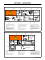
2-1. Warning Label Definitions (For Wordless Labels)
1 Warning! Watch Out! There are
possible hazards as shown by the
symbols.
2 Electric shock from wiring can kill.
3 Disconnect input plug or power
before working on machine.
4 Moving parts, such as fans, can cut
fingers and hands and cause injury.
Keep away from moving parts.
5 Wear safety glasses with side
shields.
6 Read the Owner’s Manual before
working on this machine.
7 Read the labels on the welding
power source, wire feeder, or other
major equipment for welding safety
information.
8 Recycle or dispose of used coolant
in an environmentally safe way.
9 Do not remove or paint over (cover)
the label.
1 2 3 4 5
6
7 8 9
100 h. Std.
(B)050024004
207290-B
1 Warning! Watch Out! There are
possible hazards as shown by the
symbols.
2 Disconnect input plug or power
before working on machine.
3 Wear safety glasses with side
shields.
4 Plugged filter or hoses cause
overheating and damage.
5 Read Owner’s Manual.
6 Check and clean filter every 100
hours; also check condition of hoses.
7 Use Blue Liquid (B) 050024004 when
MIG (GMAW) welding, TIG (GTAW)
welding using high frequency, and
where liquid contacts aluminum parts.
21 3
6
4
7
5

OM-254 203 Page 6
956.142.629-B
1
2
1 Warning! Watch Out! There
are possible hazards as
shown by the symbols.
2 Moving parts, such as fans,
can cut fingers and hands and
cause injury. Keep away from
moving parts.
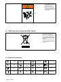
2-2. WEEE Label (For Products Sold Within The EU)
Do not discard this product (where
applicable) with general waste.
Reuse or recycle Waste Electrical
and Electronic Equipment (WEEE)
by disposing at a designated collec-
tion facility.
Contact your local recycling office
or your local distributor for further
information.
2-3. Symbols And Definitions
A
Amperes Alternating Current Voltage Input
Circulating Unit
With Coolant Pump
V
Volts
Water (Coolant)
Input
Water (Coolant)
Output
Line Connection
Protective Earth
(Ground)
IP
Degree Of
Protection
I
1
Primary Current
Hz
Hertz
On Off
U
1
Primary Voltage Single Phase

OM-254 203 Page 7
SECTION 3 − SPECIFICATIONS
3-1. Important Information Regarding CE Products (Sold Within The EU)
! This equipment shall not be used by the general public as the EMF limits for the general public might be exceeded during welding.
This equipment is built in accordance with EN 60974−1 and is intended to be used only in an occupational environment (where the general public
access is prohibited or regulated in such a way as to be similar to occupational use) by an expert or an instructed person.
Wire feeders and ancillary equipment (such as torches, liquid cooling systems and arc striking and stabilizing devices) as part of the welding
circuit may not be a major contributor to the EMF. See the Owner’s Manuals for all components of the welding circuit for additional EMF exposure
information.
The EMF assessment on this equipment was conducted at 0.5 meter.
At a distance of 1 meter the EMF exposure values were less than 20% of the permissible values.
ce-emf 1 2010-10
3-2. Serial Number And Rating Label Location
The serial number and rating information for this product is located on the back panel. Use rating label to determine input power requirements and/or
rated output. For future reference, write serial number in space provided on cover of this manual.
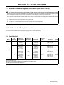
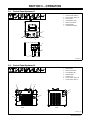
3-3. Specifications*
Model
Coolant
Tank
Capacity
Maximum
Cooling Capacity
IP Degree Of
Protection
Input Power
Input Power
Cord with
Plug
Dimensions Weight
Hydracool 1 8 L 1670 Watts
(5698 BTU/hr)
1.0 L/min
(1.1 qt/min)
IP21
Single Phase
115 VAC
50/60 Hz
2.5 Amperes
2 m Length: 305 mm
Height: 674 mm
Width: 263 mm
20.7 kg
8 L 1670 Watts
(5698 BTU/hr)
1.0 L/min
(1.1 qt/min)
IP21
Single Phase
230 VAC
50/60 Hz
1.3 Amperes
2 m** Length: 305 mm
Height: 674 mm
Width: 263 mm
20.7 kg
Hydracool 2 8 L 1760 Watts
(6005 BTU/hr)
1.0 L/min
(1.1 qt/min)
IP23
Single Phase
115 VAC
50/60 Hz
2.5 Amperes
2 m Length: 585 mm
Height: 286 mm
Width: 324 mm
20.8 kg
8 L 1760 Watts
(6005 BTU/hr)
1.0 L/min
(1.1 qt/min)
IP23
Single Phase
230 VAC
50/60 Hz
1.3 Amperes
2 m** Length: 585 mm
Height: 286 mm
Width: 324 mm
20.8 kg
*IEC Cooling Capacity States That The Water Inlet Temperature Can Not Exceed 40C Above Ambient Temperature At A 1l/ Min Flow Rate.
**Plug Is Customer Supplied.
Recirculating Coolant System For Water-Cooled GTAW Torches And GMAW Guns.
Use With Guns/Torches Rated Up To 600 Amperes

OM-254 203 Page 8
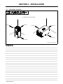
SECTION 4 − INSTALLATION
4-1. Selecting a Location
Position unit so air can circulate.
956142899_1-A, 956142900_1-A
500 mm
500 mm
500 mm
500 mm
500 mm
500 mm
Notes

OM-254 203 Page 9
SECTION 5 − OPERATION
5-1. Control Panel Hydracool 1
1 Quick Connect; Water In
2 Quick Connect; Water Out
3 Flow Indicator
4 Circuit Breaker (CB1)
5 Power On/Off switch
6 Tank Filler Neck
7 Coolant level Indicator
1
2
3
4
5
956142899_2-A
6
7
5-2. Control Panel Hydracool 2
1 Flow Indicator
2 Power On/Off switch
3 Circuit Breaker CB1
4 Tank Filler Neck
5 Coolant Level
6 Quick Connect; Water Out
7 Quick Connect; Water In
Front
Back
7
956142900_2-A
1
2
3
4
5
6

OM-254 203 Page 10
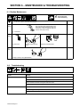
SECTION 6 − MAINTENANCE & TROUBLESHOOTING
6-1. Routine Maintenance
! Disconnect power
before maintaining.
= Check = Change = Clean = Replace
* To be done by Factory Authorized Service Agent
Reference
Every
3
Months
NOTICE − Clean coolant filter. Severe condi-
tions may require more frequent cleaning (con-
tinuous use, high/low temperatures, dirty envi-
ronment, etc.). Failure to properly clean cool-
ant filter voids pump warranty.
Coolant Filter
Every
6
Months
Cracked Parts Change Coolant (If Using
Water)
Replace Unreadable Labels
Every
12
Months
Change Coolant (If Using (B)050024004)
6-2. Troubleshooting
Trouble Remedy
Coolant system does not work.
Be sure input power cord is plugged in to energized receptacle.
Check circuit breakers on cooler and welding power source, and reset if necessary.
Motor overheated. Unit starts running when motor has cooled.
Have Factory Authorized Service Agent check Power switch, capacitor, and motor.
Decreased or no coolant flow. Add coolant.
Check for clogged or damaged hoses.
Check in-line filter, clean if require.

OM-254 203 Page 11
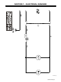
SECTION 7 − ELECTRICAL DIAGRAM
956142901_B

OM-254 203 Page 12
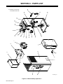
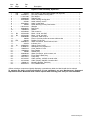
SECTION 8 − PARTS LIST
Hardware is common and
not available unless listed.
956142899_3-A
3
2
1
20
19
18
17
16
15
14
13
12
21
22
23
24
25
26
27
28
11
8
10
9
7
6
5
Figure 8-1. Main Assembly, Hydracool 1

OM-254 203 Page 13
Description
Part
No.
Dia.
Mkgs.
Item
No.
Figure 8-1. Main Assembly, Hydracool 1
1 FM 213072 Fan, muffin 115V 60HZ 3400 RPM 6.378 mtg holes 1... ... ...... .. ..................
1 FM 056126077 Fan Assy, Radiator Cooling 230 V 1... ... ... .. .................................
2 +116117082 Fan Support 1... .......... .. ....................................................
3 056082099 Radiator Assy 1... ........... .. ...................................................
4 956142629 Label, warning moving parts 1... ........... .. ......................................
5 207290 Label, advisory service 1... .............. .. ...........................................
6 956142621 Label, coolant level 1... ........... .. ..............................................
7 180663 Label, Warning Primary Connections 1... .............. .. ...............................
8 +156121044 Wrapper 1... .......... .. .......................................................
9 656049051 Barb, hose 2... ........... .. .....................................................
10 156009079 Washer 2... ........... .. ........................................................
11 027042002 Tank, water 8 L 1... ........... .. .................................................
12 M1 057010059 Motor, 170 W, 230 VAC 1... ... ... .. ..........................................
12 M1 057010060 Motor, 170 W, 230 VAC 1... ... ... .. ..........................................
13 556049386 Connector, male 3/8 d.10 2... ........... .. .........................................
14 166564 Filter, in−line low profile 100 screen 3/8 hose bar 1... .............. .. ....................
15 CB1 083432 Breaker, Circuit 10A 1... ... ...... .. .............................................
16 556049410 Water Connection, Quick Connect, blue 1... ........... .. ............................
17 215279 Indicator, flow 1... .............. .. ...................................................
18 S1 056067251 Switch, Power On/Off 1... .... ... .. ............................................
19 316029721 Nameplate, front, hydracool 1 1... ........... .. .....................................
20 756007013 Cover, Switch 37 x 20 1... ........... .. ............................................
21 156033034 Boot, Rubber 1... ........... .. ...................................................
22 195585 Handle Assy 1... .............. .. ....................................................
23 556049409 Water Connection, quick connect, red 1... ........... .. ..............................
24 156006074 Front, Base & Rear Assy 1... ........... .. .........................................
25 V57011071 Pump Assy 1... ........... .. .....................................................
26 027112327 Cable, primary, 115VAC c/w strain relief 1... ........... .. ............................
26 027112328 Cable, primary, 230VAC c/w strain relief 1... ........... .. ............................
27 156009147 Mounting Bracket, Tank Assy 1... ........... .. .....................................
28 656110013 Foot, Rubber Mount 4... ........... .. .............................................
+When ordering a component originally displaying a precautionary label, the label should also be ordered.
To maintain the factory original performance of your equipment, use only Manufacturer’s Suggested
Replacement Parts. Model and serial number required when ordering parts from your local distributor.

OM-254 203 Page 14
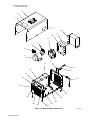
Hardware is common and
not available unless listed.
Figure 8-2. Main Assembly, Hydracool 2 956142900_3-A
1
2
3
4
12
11
10
9
8
7
6
5
13
14
15
16
17
18
19
20
21
22
23
24
25
26
27
28
29

OM-254 203 Page 15
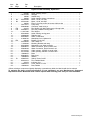
Description
Part
No.
Dia.
Mkgs.
Item
No.
Figure 8-2. Main Assembly, Hydracool 2
1 207290 Label, advisory service 1... .............. .. ...........................................
2 +156121028 Wrapper 1... .......... .. .......................................................
3 195585 Handle Assy 1... .............. .. ....................................................
4 180663 Label, warning primary connections 1... .............. .. ................................
5 M1 057010059 Motor, 170 W, 115 VAC 1... ... ... .. ..........................................
5 M1 057010060 Motor, 170 W, 230 VAC 1... ... ... .. ..........................................
6 166564 Filter, in−line low profile 100 screen 3/8 hose bar 1... .............. .. ....................
7 V57011071 Pump Assy 1... ........... .. .....................................................
8 556049386 Connector, male 3/8 d.10 2... ........... .. .........................................
9 FM 213072 Fan, Muffin 115V 60HZ 3400 rpm 6.378 mtg holes 1... ... ...... .. ...................
9 FM 056126077 Fan Assy, Radiator Cooling 230 V 1... ... ... .. .................................
10 +116117082 Fan Support 1... .......... .. ....................................................
11 956142629 Label, warning moving parts 1... ........... .. ......................................
12 056082099 Radiator Assy 1... ........... .. ...................................................
13 956142621 Label, coolant level 1... ........... .. ..............................................
14 316029722 Nameplate, front, Hydracool 2 1... ........... .. .....................................
15 CB1 083432 Breaker, Circuit 10A 1... ... ...... .. .............................................
16 027042002 Tank, Water 8 L 1... ........... .. .................................................
17 116122306 Mounting Bracket, tank assy 1... ........... .. ......................................
18 956142908 Nameplate, rear, water terminals 1... ........... .. ..................................
19 556049410 Water Connection, quick connect, blue 1... ........... .. .............................
20 556049409 Water Connection, Quick Connect, red 1... ........... .. .............................
21 027112327 Cable, primary, 115VAC c/w strain relief 1... ........... .. ............................
21 027112328 Cable, primary, 230VAC c/w strain relief 1... ........... .. ............................
22 156006075 Base 1... ........... .. ..........................................................
23 656049051 Barb, hose 2... ........... .. .....................................................
24 156009079 Washer 2... ........... .. ........................................................
25 S1 056067251 Switch, Power On/Off 1... .... ... .. ............................................
26 656110013 Foot, Rubber Mount 4... ........... .. .............................................
27 215279 Indicator, flow 1... .............. .. ...................................................
28 756007013 Cover, Switch 37 x 20 1... ........... .. ............................................
29 156033034 Boot, Rubber 1... ........... .. ...................................................
+When ordering a component originally displaying a precautionary label, the label should also be ordered.
To maintain the factory original performance of your equipment, use only Manufacturer’s Suggested
Replacement Parts. Model and serial number required when ordering parts from your local distributor.

Notes
Page is loading ...
Page is loading ...
Page is loading ...
Page is loading ...
-
 1
1
-
 2
2
-
 3
3
-
 4
4
-
 5
5
-
 6
6
-
 7
7
-
 8
8
-
 9
9
-
 10
10
-
 11
11
-
 12
12
-
 13
13
-
 14
14
-
 15
15
-
 16
16
-
 17
17
-
 18
18
-
 19
19
-
 20
20
-
 21
21
-
 22
22
-
 23
23
-
 24
24


Miller HYDRACOOL 1 CE Owner's manual
- Category
- Welding System
- Type
- Owner's manual
- This manual is also suitable for
Ask a question and I''ll find the answer in the document
Finding information in a document is now easier with AI
Other documents
-
HobartWelders HANDLER 210 MVP Owner's manual
-
-
HobartWelders HANDLER 190 AND H100S4-10 GUN Owner's manual
-
-
Miller Electric OM-180 800 Owner's manual
-
Miller Electric SWLL-115 Owner's manual
-
-
-
-