Miller Coolmate 3 Owner's manual

Category
Welding System
Type
Owner's manual

This manual is also suitable for

Miller Coolmate 3 is a versatile and efficient recirculating coolant system designed to provide optimum cooling for water-cooled GTAW torches and GMAW guns rated up to 600 amperes. With a large 3-gallon tank capacity and a maximum cooling capacity of 14,000 BTU/hr, it ensures a consistent and reliable flow of coolant to prevent overheating and maintain peak performance of your welding equipment. Its compact design, IP23 rating for protection against dust and water ingress, and easy-to-use controls make it suitable for various industrial and professional welding applications.

Miller Coolmate 3 is a versatile and efficient recirculating coolant system designed to provide optimum cooling for water-cooled GTAW torches and GMAW guns rated up to 600 amperes. With a large 3-gallon tank capacity and a maximum cooling capacity of 14,000 BTU/hr, it ensures a consistent and reliable flow of coolant to prevent overheating and maintain peak performance of your welding equipment. Its compact design, IP23 rating for protection against dust and water ingress, and easy-to-use controls make it suitable for various industrial and professional welding applications.

OWNER’S MANUAL
OM-628D 174 791D
September 1998
And Non-CE Models
Coolmate 3
1. Specifications
Recirculating Coolant System For Water-Cooled GTAW Torches And GMAW Guns
Use With Guns/Torches Rated Up To 600 Amperes
IP Rating: 23
3 gal (11.4 L) Coolant Tank Capacity;
Maximum Cooling Capacity: 14,000 BTU/hr At 1.25 qt/min (1.2 L/min)
Dimensions: 23 in (584 mm) Long, 12 in (305 mm) Wide, 13-1/4 in (337 mm) High
Weight: 39 lb (18 kg)
ST-801 189-A
Dimensions: 23 in (584 mm) Long, 12 in (305 mm) Wide, 13-1/4 in (337 mm) High
Weight: 39 lb (18 kg)
ST-801 189-A
115 Volt Models Use 5.9 Amperes, 50/60 Hertz, Single-Phase Input Power
230 Volt Models Use 3 Amperes, 50/60 Hertz, Single-Phase Input Power
2. Safety Symbol Definitions
Means Warning! Watch Out! There are possible hazards
with this procedure! The possible hazards are shown in
the adjoining symbols.
Symbole graphique d’avertissement! Attention! Cette
procédure comporte des risques possibles! Les dangers
éventuels sont représentés par les symboles graphiques
joints.
Have only trained and qualified persons install, operate,
or service this unit. Call your distributor if you do not
understand the directions. For WELDING SAFETY and
EMF information, read wire feeder and welding power
source manuals.
L’installation, l’exploitation et l’entretien de cet appareil
doivent être confiés uniquement à des personnes
qualifiées et convenablement formées. S’adresser à un
distributeur si l’on ne comprend pas les directives. Pour
des renseignements ayant trait à la SÉCURITÉ lors du
soudage et aux champs électromagnétiques, consulter
les manuels traitant les dévidoirs et les sources de
courant pour le soudage.
Beware of electric shock from wiring.
Attention! Risque d’électrocution due au contact avec
des fils.
Beware of moving parts.
Attention! Pièces en mouvement.
Wear safety glasses with side shields.
Porter des lunettes de sécurité avec protections
latérales.
Recycle or dispose of used coolant in an environmen-
tally safe way.
Recycler ou éliminer tout liquide de refroidissement usé
conformément aux méthodes prescrites pour assurer la
protection de l’environnement.
OM-628 Page 2
3. Warning Label Definitions For CE Products
S-180 663
1 2 3 4 5
6
7 8 9
1 Warning! Watch Out! There are
possible hazards as shown by the
symbols.
2 Electric shock from wiring can kill.
3 Disconnect input plug or power before
working on machine.
4 Moving parts, such as fans, can cut
fingers and hands and cause injury.
Keep away from moving parts.
5 Wear safety glasses with side shields.
6 Read the Owner’s Manual before
working on this machine.
7 Read the labels on the welding power
source, wire feeder, or other major
equipment for welding safety
information.
8 Recycle or dispose of used coolant in
an environmentally safe way.
9 Do not remove or paint over (cover)
the label.
4/96
S-178 910
=
043 810 (HF)
043 809 (AL)
100 h. std.
21 3
6
4
7
5
1 Warning! Watch Out! There are
possible hazards as shown by the
symbols.
2 Disconnect input plug or power before
working on machine.
3 Wear safety glasses with side shields.
4 Plugged filter or hoses cause
overheating and damage.
5 Read Owner’s Manual.
6 Check and clean filter every 100
hours; also check condition of hoses.
7 Use Low Conductivity Coolant No.
043 810 for High-Frequency assisted
or Gas Tungsten Arc Welding
applications. Use Aluminum
Protecting Coolant No. 043 809 where
coolant contacts aluminum parts or for
Gas Metal Arc Welding applications or
where High Frequency is not used.
OM-628 Page 3
4. Rating Label
S/N: KG085472
043007
115
5.9
COOLMATE 3
Hz50/60
IP 23
V
U
1
=
A
I
1
=
1
NRTL/C
LR5071
5. Symbols And Definitions
Some symbols are found only on CE products.
NOTE
A
Amperes Alternating Current Voltage Input
Circulating Unit
With Coolant
Pump
V
Volts
Water (Coolant)
Input
Water (Coolant)
Output
Line Connection
Protective Earth
(Ground)
IP
Degree Of
Protection
I
1
Primary Current
Hz
Hertz
On Off
U
1
Primary Voltage Single Phase
OM-628 Page 4
6. Preparing Cooling Unit For Use
ST-801 193-B
1 Coolant Out Hose
2 Coolant In Hose
Fittings have 5/8-18 left-hand
threads. Connect hoses with prop-
er fittings as shown.
3 Coolant Tank Cap
Use table to select proper coolant,
and fill tank. Maintain coolant level
at approximately 1 in (25 mm) be-
low top of filler neck.
4 Flow Indicator
5 Power Switch
Low Conductivity Coolant
No. 043 810**;
Distilled Or Deionized Water
OK Above 32° F (0° C)
Low Conductivity Coolant
No. 043 810**; Or
Aluminum Protecting Coolant
No. 043 809**;
Distilled Or Deionized Water
OK Above 32° F (0° C)
Tools Needed:
5/8 in
1
2
3
4 5
GTAW Or Where
HF* Is Used
GMAW Or Where
HF* Is Not Used
Application
*HF: High Frequency Current
**Coolants 043 810 and 043 809 protect to -37° F (-38°C) and resist algae growth.
Coolant
Aluminum Protecting
Coolant No. 043 809**
Where Coolant Contacts
Aluminum Parts
OM-628 Page 5
7. Connections
ST-801 190-B / ST-801 191-B
1 Lift -Eye
If placing cooling unit on welding
power source, slots are provided in
bottom of unit so it fits over lift-eye.
To prevent overheating, make sure
cooling unit is positioned so airflow
is not restricted.
Y If welding power source has
a water valve, do not con-
nect hoses to water valve.
Connect hoses as shown.
Operation:
Turn power switch On. Flow indica-
tor spins to indicate that at least
0.53 qt/min (0.5 L/min) of coolant is
flowing.
GTAW Connections
GMAW Connections
1
OM-628 Page 6
8. Routine Maintenance
Y Disconnect power
before maintaining.
3 Months
Clean Coolant
Filter
Blow Out Heat
Exchanger Fins
6 Months
Replace
Cracked
Hoses
Replace
Unreadable
Labels
Change
Coolant (If
Using Water)
12 Months
Oil Motor
Change
Coolant (If
Using 043 809
or 043 810
Coolant)
3/8 in
Tools Needed:
9. Coolant Maintenance And Oiling Motor
ST-801 195-B / Ref. ST-801 194
1 Coolant Filter
Unscrew housing to clean filter.
Changing coolant: Drain coolant
by tipping unit forward. Fill with
clean water and run for 10 minutes.
Drain and refill.
2 Motor
Remove plugs and put about 15
drops of SAE 20 motor oil into each
oil port. Replace plugs.
. If replacing hoses, use hoses
compatible with ethylene gly-
col, such as Buna-n, Neo-
prene, or Hypalon. NOTE:
Oxy-acetylene hoses are not
compatible with any product
containing ethylene glycol.
1
2
OM-628 Page 7
10. Troubleshooting
Trouble Remedy
Coolant system does not work. Be sure input power cord is plugged in to energized receptacle.
Check line fuses or circuit breaker, and fuses F1, F2 if applicable, and replace or reset if necessary.
Motor overheated. Unit starts running when motor has cooled.
Have Factory Authorized Service Agent check Power switch S1 and motor Mot.
Decreased or no coolant flow. Add coolant.
Check for clogged hoses or coolant filter. Clean filter or clean / replace hoses if necessary.
Disconnect pump, and check for sheared coupling. Replace coupling if necessary.
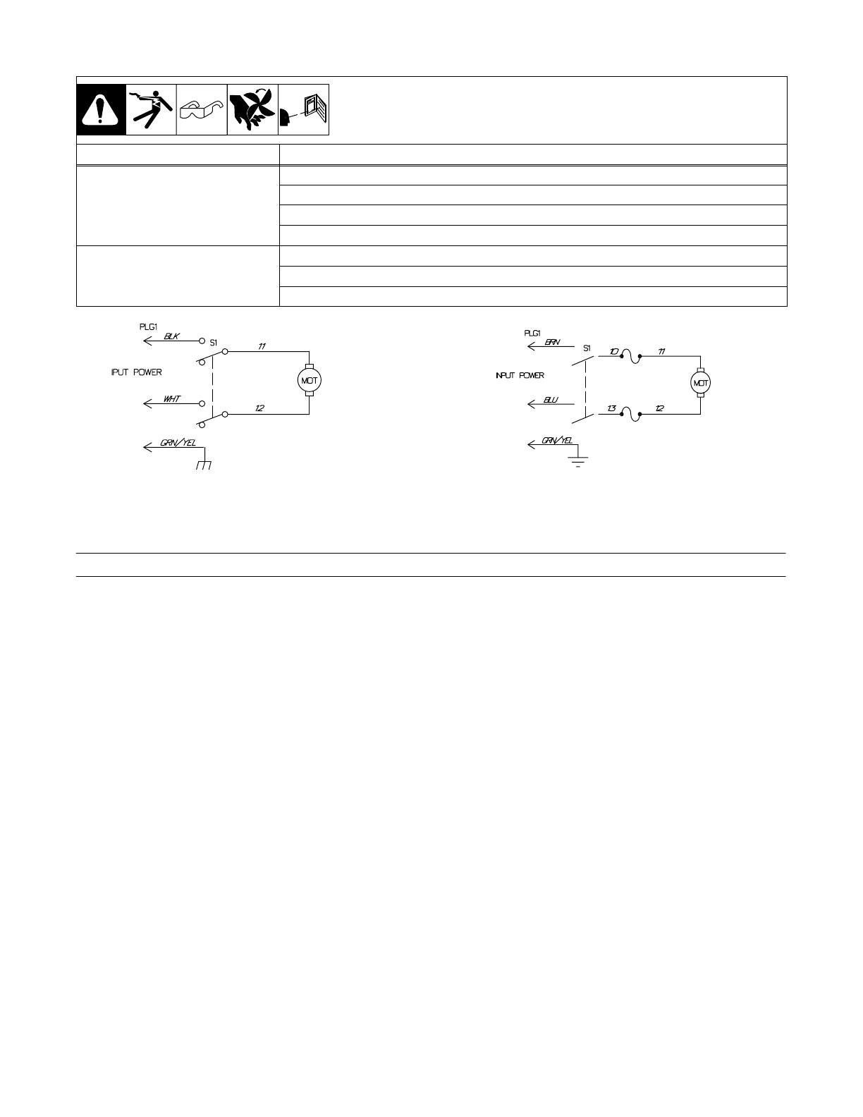
SA-135 796-D
Figure 10-1. Circuit Diagram For 115 And 230 Volt
Figure 10-2. Circuit Diagram For 230 Volt (CE Models)
SA-187 733
F1
F2
11. Parts List
Description
Part
No.
Dia.
Mkgs.
Item
No.
Figure 11-1. Complete Assembly
Quantity
1 +166 562 WRAPPER 1. . . . . . . . . . . . . . . . . . . . . . . . . . . . . . . . . . . . . . . . . . . . . . . . . . . . . . . . . . . . . . . . . . . . . . . . . . . . . . . . . . . . . . . . . . . .
2 180 663 LABEL, warning general precautionary (CE and Generic Models) 1. . . . . . . . . . . . . . . . . . . . . . . . . . . . . . . . . . . . . . . . . . . . . . .
3 178 910 LABEL, caution incorrect coolant (CE and Generic Models) 1. . . . . . . . . . . . . . . . . . . . . . . . . . . . . . . . . . . . . . . . . . . . . . . . . . . .
4 192 449 LABEL, warning general precautionary (Non-CE and Non-Generic Modles) 1. . . . . . . . . . . . . . . . . . . . . . . . . . . . . . . . . . . . . .
5 174 042 PUMP COOLANT w/CLAMPS, (consisting of) 1. . . . . . . . . . . . . . . . . . . . . . . . . . . . . . . . . . . . . . . . . . . . . . . . . . . . . . . . . . . . . . . .
6 126 992 FITTING, hose brs barbed elb M 3/8tbg x 3/8 2. . . . . . . . . . . . . . . . . . . . . . . . . . . . . . . . . . . . . . . . . . . . . . . . . . . . . . . . . . . . . . . .
7 134 795 COUPLER, drive pump 1. . . . . . . . . . . . . . . . . . . . . . . . . . . . . . . . . . . . . . . . . . . . . . . . . . . . . . . . . . . . . . . . . . . . . . . . . . . . . . . . . . .
8 MOT 173 264 MOTOR, 1/4hp 230VAC 50/60Hz 1425/1725rpm (230V model) 1. . . . . . . . . . . . . . . . . . . . . . . . . . . . . . . . . . . . . . . . . . .
8 MOT 173 263 MOTOR, 1/4hp 115VAC 50/60Hz 1425/1725rpm (115V model) 1. . . . . . . . . . . . . . . . . . . . . . . . . . . . . . . . . . . . . . . . . . .
9 166 570 BLADE, fan 9.000 5wg 38deg .500 bore cw (setscrew included) 1. . . . . . . . . . . . . . . . . . . . . . . . . . . . . . . . . . . . . . . . . . . . . . . .
10 174 044 TUBING, PVC .375 x .625 OD X 18.000 2. . . . . . . . . . . . . . . . . . . . . . . . . . . . . . . . . . . . . . . . . . . . . . . . . . . . . . . . . . . . . . . . . . . .
11 176 746 CLAMP, 1-ear type nom dim .656 x .275 wide 2. . . . . . . . . . . . . . . . . . . . . . . . . . . . . . . . . . . . . . . . . . . . . . . . . . . . . . . . . . . . . . . .
094 263 CLAMP, 1-ear type nom dim .718 x .276 wide 8. . . . . . . . . . . . . . . . . . . . . . . . . . . . . . . . . . . . . . . . . . . . . . . . . . . . . . . . . . . . . . . . . . .
12 192 454 PANEL, rear 1. . . . . . . . . . . . . . . . . . . . . . . . . . . . . . . . . . . . . . . . . . . . . . . . . . . . . . . . . . . . . . . . . . . . . . . . . . . . . . . . . . . . . . . . . . . .
13 139 042 BUSHING, strain relief .270/.480 id x .804 mtg hol 1. . . . . . . . . . . . . . . . . . . . . . . . . . . . . . . . . . . . . . . . . . . . . . . . . . . . . . . . . . . .
14 PLG1 192 458 CABLE, power 16ga 3c (230V model) 1. . . . . . . . . . . . . . . . . . . . . . . . . . . . . . . . . . . . . . . . . . . . . . . . . . . . . . . . . . . . . . . .
14 PLG1 192 457 CABLE, power 10ft 16ga (115V model) 1. . . . . . . . . . . . . . . . . . . . . . . . . . . . . . . . . . . . . . . . . . . . . . . . . . . . . . . . . . . . . .
14 PLG1 192 456 CABLE, pwr 10ft (230V CE Models only) 1. . . . . . . . . . . . . . . . . . . . . . . . . . . . . . . . . . . . . . . . . . . . . . . . . . . . . . . . . . . .
15 166 569 RADIATOR, heat exchanger 1. . . . . . . . . . . . . . . . . . . . . . . . . . . . . . . . . . . . . . . . . . . . . . . . . . . . . . . . . . . . . . . . . . . . . . . . . . . . . . .
16 168 267 TANK COOLANT 1. . . . . . . . . . . . . . . . . . . . . . . . . . . . . . . . . . . . . . . . . . . . . . . . . . . . . . . . . . . . . . . . . . . . . . . . . . . . . . . . . . . . . . . .
17 174 043 TUBING, PVC .375 ID x .625 OD x 1.250 1. . . . . . . . . . . . . . . . . . . . . . . . . . . . . . . . . . . . . . . . . . . . . . . . . . . . . . . . . . . . . . . . . . .
18 166 608 CAP, tank screw-on w/vent 1. . . . . . . . . . . . . . . . . . . . . . . . . . . . . . . . . . . . . . . . . . . . . . . . . . . . . . . . . . . . . . . . . . . . . . . . . . . . . . . .
19 182 994 TUBE, pick-up coolant 1. . . . . . . . . . . . . . . . . . . . . . . . . . . . . . . . . . . . . . . . . . . . . . . . . . . . . . . . . . . . . . . . . . . . . . . . . . . . . . . . . . . .
20 136 369 TUBING, PVC .375 ID x .625 OD x 10.000 1. . . . . . . . . . . . . . . . . . . . . . . . . . . . . . . . . . . . . . . . . . . . . . . . . . . . . . . . . . . . . . . . . .
21 178 248 HOSE, nprn brd No. 1 x .375 ID x 4.000 black 1. . . . . . . . . . . . . . . . . . . . . . . . . . . . . . . . . . . . . . . . . . . . . . . . . . . . . . . . . . . . . . .
22 166 560 RING, ring ext .500 shaft grv x .042thk 2. . . . . . . . . . . . . . . . . . . . . . . . . . . . . . . . . . . . . . . . . . . . . . . . . . . . . . . . . . . . . . . . . . . . . .
23 166 564 FILTER, in-line 1. . . . . . . . . . . . . . . . . . . . . . . . . . . . . . . . . . . . . . . . . . . . . . . . . . . . . . . . . . . . . . . . . . . . . . . . . . . . . . . . . . . . . . . . . .
24 168 254 CLIP, filter mounting 1. . . . . . . . . . . . . . . . . . . . . . . . . . . . . . . . . . . . . . . . . . . . . . . . . . . . . . . . . . . . . . . . . . . . . . . . . . . . . . . . . . . . .
F1, F2 011 116 FUSE, mintr gl slo-blo 7A 250V (230V CE Models only) 2. . . . . . . . . . . . . . . . . . . . . . . . . . . . . . . . . . . . . . . . . . . . . . . . . . . .
098 376 HOLDER, fuse mintr (230V CE Models only) 1. . . . . . . . . . . . . . . . . . . . . . . . . . . . . . . . . . . . . . . . . . . . . . . . . . . . . . . . . . . . . . . . . . . .
25 174 047 NUT, .250-20 special 4. . . . . . . . . . . . . . . . . . . . . . . . . . . . . . . . . . . . . . . . . . . . . . . . . . . . . . . . . . . . . . . . . . . . . . . . . . . . . . . . . . . . .
26 186 003 INDICATOR, flow (consisting of) 1. . . . . . . . . . . . . . . . . . . . . . . . . . . . . . . . . . . . . . . . . . . . . . . . . . . . . . . . . . . . . . . . . . . . . . . . . . .
27 166 568 PADDLE, flow indicator 1. . . . . . . . . . . . . . . . . . . . . . . . . . . . . . . . . . . . . . . . . . . . . . . . . . . . . . . . . . . . . . . . . . . . . . . . . . . . . . . . . . .
28 166 566 O-RING, 1.301 ID x .070CS 1. . . . . . . . . . . . . . . . . . . . . . . . . . . . . . . . . . . . . . . . . . . . . . . . . . . . . . . . . . . . . . . . . . . . . . . . . . . . . . .
29 186 005 LENS, flow indicator 1. . . . . . . . . . . . . . . . . . . . . . . . . . . . . . . . . . . . . . . . . . . . . . . . . . . . . . . . . . . . . . . . . . . . . . . . . . . . . . . . . . . . .
30 S1 177 396 SWITCH, rocker DPST 15A 250VAC 1. . . . . . . . . . . . . . . . . . . . . . . . . . . . . . . . . . . . . . . . . . . . . . . . . . . . . . . . . . . . . . . . . . .
31 177 399 PANEL, front 1. . . . . . . . . . . . . . . . . . . . . . . . . . . . . . . . . . . . . . . . . . . . . . . . . . . . . . . . . . . . . . . . . . . . . . . . . . . . . . . . . . . . . . . . . . . .
32 NAMEPLATE, (order by model and serial number) 1. . . . . . . . . . . . . . . . . . . . . . . . . . . . . . . . . . . . . . . . . . . . . . . . . . . . . . . . . . . . . . . . . . . . .
33 166 571 FITTING, coolant barbed 3/8tbg 5/8-18 female 2. . . . . . . . . . . . . . . . . . . . . . . . . . . . . . . . . . . . . . . . . . . . . . . . . . . . . . . . . . . . . . .
+When ordering a component originally displaying a precautionary label, the label should also be ordered.
BE SURE TO PROVIDE MODEL AND SERIAL NUMBER WHEN ORDERING REPLACEMENT PARTS.
OM-628 Page 8
*Included in Item 23
ST-801 196-C
1
2
3
4
5
6
7
8
9
10
11
12
13
14
15
16
17
18
19
20
21
21
22
10
19
23
24
20
25
10
10
26
17
27
28
29
26
30
31
32
*
33
Figure 11-1. Complete Assembly
dec_con1 1/96
1996 MILLER Electric Mfg. Co.
Declaration of Conformity for
European Community (CE) Products
This information is provided for units with CE certification (see rating label on unit).
NOTE
Manufacturer’s Name: Miller Electric Mfg. Co.
Manufacturer’s Address: 1635 W. Spencer Street
Appleton, WI 54914 USA
Declares that the product: COOLMATE 3
conforms to the following Directives and Standards:
Directives
Electromagnetic compatibility Directives: 89/336/EEC, 92/31/EEC
Low Voltage Directive: 73/23/EEC
Machinery Directives: 89/392/EEC, 91/368/EEC, 93/C 133/04, 93/68/EEC
Standards
Electromagnetic compatibility (EMC) Product standard for arc welding equipment: EN50199: August 1995
Safety Requirements for Arc Welding Equipment part 1: EN 60974-1: 1989
Arc Welding Equipment Part 1: Welding Power Sources: IEC 974-1 (April 1995 - Draft revision)
Degrees of Protection provided by Enclosures (IP code): IEC 529: 1989
European Contact: Mr. Luigi Vacchini, Managing Director
MILLER Europe S.P.A.
Via Privata Iseo 6/E
20098 San Giuliano
Milanese, Italy
Telephone: 39(02)98290-1
Fax: 39(02)98290-203
S/N: KG085472
043007
115
5.9
COOLMATE 3
Hz50/60
IP 23
MILLER ELECTRIC MFG. CO., APPLETON, WI USA
V
U
1
=
A I
1
=
1
  • Page 1 1
  • Page 2 2
  • Page 3 3
  • Page 4 4
  • Page 5 5
  • Page 6 6
  • Page 7 7
  • Page 8 8
  • Page 9 9

Miller Coolmate 3 Owner's manual

Category
Welding System
Type
Owner's manual
This manual is also suitable for

Miller Coolmate 3 is a versatile and efficient recirculating coolant system designed to provide optimum cooling for water-cooled GTAW torches and GMAW guns rated up to 600 amperes. With a large 3-gallon tank capacity and a maximum cooling capacity of 14,000 BTU/hr, it ensures a consistent and reliable flow of coolant to prevent overheating and maintain peak performance of your welding equipment. Its compact design, IP23 rating for protection against dust and water ingress, and easy-to-use controls make it suitable for various industrial and professional welding applications.

Ask a question and I''ll find the answer in the document

Finding information in a document is now easier with AI