Raymarine Ray430 User manual
- Category
- Musical Equipment
- Type
- User manual
This manual is also suitable for
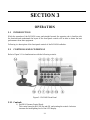
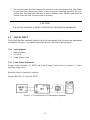
Raymarine GPS Receiver Ray430 The Raymarine GPS Receiver Ray430 is a multifunction device that combines the functionality of a loudhailer, foghorn, intercom, and audio amplifier. It features a rugged, waterproof construction and an easy-to-use interface with an illuminated keyboard and LCD display.
Raymarine GPS Receiver Ray430 The Raymarine GPS Receiver Ray430 is a multifunction device that combines the functionality of a loudhailer, foghorn, intercom, and audio amplifier. It features a rugged, waterproof construction and an easy-to-use interface with an illuminated keyboard and LCD display.


-
 1
1
-
 2
2
-
 3
3
-
 4
4
-
 5
5
-
 6
6
-
 7
7
-
 8
8
-
 9
9
-
 10
10
-
 11
11
-
 12
12
-
 13
13
-
 14
14
-
 15
15
-
 16
16
-
 17
17
-
 18
18
-
 19
19
-
 20
20
-
 21
21
-
 22
22
-
 23
23
-
 24
24
-
 25
25
-
 26
26
-
 27
27
-
 28
28
-
 29
29
-
 30
30
-
 31
31
-
 32
32
-
 33
33
-
 34
34
-
 35
35
-
 36
36
-
 37
37
-
 38
38
-
 39
39
-
 40
40
-
 41
41
-
 42
42
-
 43
43
-
 44
44
-
 45
45
-
 46
46
-
 47
47
-
 48
48
-
 49
49
-
 50
50
-
 51
51
-
 52
52
-
 53
53
-
 54
54


Raymarine Ray430 User manual
- Category
- Musical Equipment
- Type
- User manual
- This manual is also suitable for
Raymarine GPS Receiver Ray430 The Raymarine GPS Receiver Ray430 is a multifunction device that combines the functionality of a loudhailer, foghorn, intercom, and audio amplifier. It features a rugged, waterproof construction and an easy-to-use interface with an illuminated keyboard and LCD display.
Ask a question and I''ll find the answer in the document
Finding information in a document is now easier with AI
Related papers
-
Raymarine Ray 201 Owner's manual
-
-
-
-
-
Raymarine RAY91 Installation & Operation Instructions
-
Raymarine Ray 55E Owner's Owner's Handbook Manual
-
-
-
Other documents
-
 T'nB TNBTCUNSLIM1 Datasheet
-
Unbranded Hail Guard, Hooded 555641 Installation guide
-
Reznor R6GN Installation guide
-
LY International Electronics H-W02 Owner's manual
-
Furuno LH-3010 User manual
-
-
Broan Hail Guards, 547846, 547847, 558857, 559411 Installation guide
-
Reznor R8GE Installation guide
-
-
Altronix ALSD2 User manual
