Page is loading ...

1

2

3
Introduction / Table of Contents Step One
An ultrasonic sound wave is pulsed from the base of the transducer. The sound wave reflects against the
process medium below it. The sound wave energy is returned to the transducer. The microprocessor based
electronics measures the time of flight between the sound pulse generation and its receipt. This translates into
the distance or range between the transducer and process media below.
NEW FEATURES
Reflective Ultrasonic Technology
Simple configuration with push button or LVCN414-SW software configuration
Increased temperature range
Increased output filtering
TABLE OF CONTENTS
Introduction: ...................................................................................................................................................... 3
Specifications: ........................................................................................................................................... 5
Dimensions: .............................................................................................................................................. 6
Reflective Technology: .............................................................................................................................. 7
About this manual: .................................................................................................................................... 8
Getting Started: ..................................................................................................................................................... 9
Setup Overview: ........................................................................................................................................ 9
Components: ............................................................................................................................................ 1-
LVCN414-SW software vs. Display Configuration: ................................................................................. 11
Understanding Sensor Height (Height): .................................................................................................. 12
Understanding Fill-Height (Fill-H): ...................................................................................................... 13-14
Sensor Output to Local Display: ............................................................................................................. 15
Configuration (with LVCN414-SW software): ..................................................................................................... 16
Step 1 – Install LVCN414-SW software: ................................................................................................. 17
LVCN414-SW software System Requirements: .......................................................................... 17
USB Fob Interface: ...................................................................................................................... 18
Step 2 – Measure the Tank: .................................................................................................................... 19
Step 3 – Sensor Configuration: ............................................................................................................... 20
Step 4 – Dimensional Entry: ................................................................................................................... 21
Step 5 – Tank Level Confirmation: .......................................................................................................... 22
Step 6 – Write to Unit: ............................................................................................................................. 22
Configuration
(
with Display): ................................................................................................................................ 23
Step1 – Measure Tank: ........................................................................................................................... 24
Step 2 – Setting the Units of Measurement: ........................................................................................... 25
Step 3 – Setting the Height: .................................................................................................................... 26
Step 4 – Setting the Fill-H: ...................................................................................................................... 27
Step 5 – Setting the Fail-Safe Current Output: ....................................................................................... 28
Installation: .......................................................................................................................................................... 29
Mounting Guide: ...................................................................................................................................... 29
Fitting Selection: ................................................................................................................................ 30-32

4
Introduction / Table of Contents Step One
Wiring: ................................................................................................................................................................ 33
Wiring Diagram – Sample: ...................................................................................................................... 33
Wiring LVU700 series: ............................................................................................................................ 33
Wire Connections: ................................................................................................................................... 34
General Notes for Electrical Connections, Usage and Safety: ............................................................... 34
Analog Output: ........................................................................................................................................ 35
Voltage Output: ....................................................................................................................................... 35
Common Wiring to Displays, Controllers & PLCs: .................................................................................. 36
LVCN414-SW software Appendix: ...................................................................................................................... 37
Sensor Configuration: ........................................................................................................................ 37-38
Volumetric Configuration: ................................................................................................................... 39-41
Tank Level Confirmation: ........................................................................................................................ 42
“Write to Unit” .......................................................................................................................................... 43
Display Appendix: ............................................................................................................................................... 44
Air Gap vs. Liquid Level: ......................................................................................................................... 44
How to reverse the current output (Rev mA): ......................................................................................... 45
How to Setup to Start-up Power: ............................................................................................................ 46
Values Menu: .......................................................................................................................................... 47
SETUP: ....................................................................................................................................... 47
Diagnostic (DIAG) parameters: ................................................................................................... 47
Reset: .......................................................................................................................................... 48
Appendix: ............................................................................................................................................................ 49
Factory Settings: ..................................................................................................................................... 49
User Settings: ......................................................................................................................................... 49
Troubleshooting: ................................................................................................................................ 49-50
Warranty: ............................................................................................................................................................ 51

5
Introduction (continued) Step One
SPECIFICATIONS
Electrical:
Supply Voltage: 14-28 Vdc
Signal: 4 to 20 mA current loop; 22 mA
max.
Mechanical:
Display Module: Removable via short cable and
plug
LCD: 6 characters, 10 mm (0.394”)
height
Buttons: Three, UP / OK / DN
Pin Connection: Display can be removed such
that the open connection allows
the sensor to be LVCN414-SW
software capable.
Enclosure: Polypropylene head with skirt to
support transducer w/ conduit
Conduit Connection: Single, 1/2 inch NPT
Transducer: Black, PVDF with FKM gasket
Process Mount: LVU706: 2" NPT or 2” G
LVU712: 3” NPT or 3” G
Gasket FKM (G thread only)
Electrical Connections:
Power & Return: 2-pin removable terminal block
Display Connect.: 4-pin removable terminal pins
Non-Display
version.: Block optional with FOB
* Earth ground on package
external
Environmental:
Process Temp.: -40 to 80 °C (-40 to 176 °F)
Temp. comp.: Automatic
Ambient Temp.: -35 to 60 °C (-31 to 140 °F)
Pressure: 30 psi, derated @ 1.667 psi per
degree C above 25 °C
Enclosure: NEMA 6P, IP68
Functional:
Range: LVU706: 6.0m (19.69 feet)
LVU712: 12.0m (39.4 feet)
Dead band: LVU706: 20cm (8 inches)
LVU712: 45.7cm (18 inches)
Accuracy: 0.2% of Range in air at 20 °C
Resolution: LVU706: 2mm (0.079 inches)
LVU712: 5mm (0..196 inches)
Beam width: LVU706: 7.6cm (3 inches)
LVU712: 15.2cm (6 inches)
Menu: Self-scrolling

6
Introduction (continued) Step One
DIMENSIONS
Dimensions for LVU706 Series
Dimensions for LVU712 Series

7
Introduction (continued) Step One
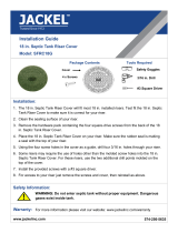
REFLECTIVE TECHNOLOGY
Condensation is the most common variable in liquid level applications. Condensation attenuates the acoustic
signal of ultrasonic sensors with horizontal transducers, weakening their signal strength and signal to noise
ratio by up to 50%, and substantially reducing their measurement reliability. At the core of Reflective
Technology™ is a simple fact. Unlike flat horizontal surfaces, significant water droplets cannot adhere to
smooth vertical surfaces. By orienting the transducer vertically, condensation runs off the transducer and does
not affect sensor performance. The unimpeded transmit and receive signals are redirected to and from the
liquid off a 45º reflector, delivering reliable level measurement.
FLAT TRANSDUCER REFLECTIVE TRANSDUCER
Signal Attenuation Reliable Measurement

8
Introduction (continued) Step One
About this Manual: PLEASE READ THE ENTIRE MANUAL PRIOR TO INSTALLING OR USING THIS
PRODUCT. This manual includes information on the LVU700 series Ultrasonic Level Transmitter from
OMEGA ENGINEERING. Please refer to the part number located on the switch label to verify the exact model
configuration, which you have purchased.
User’s Responsibility for Safety: OMEGA ENGINEERING manufactures a broad range of level sensing
technologies. While each of these sensors is designed to operate in a wide variety of applications, it is the
user’s responsibility to select a sensor model that is appropriate for the application, install it properly, perform
tests of the installed system, and maintain all components. The failure to do so could result in property
damage or serious injury.
Proper Installation and Handling: Only professional staff should install and/or repair this product. Never
over tighten the sensor within the fitting. Always check for leaks prior to system start-up.
Wiring and Electrical: A supply voltage of 14 to 28 VDC is used to power the LVU700 series. Electrical
wiring of the transmitter should be performed in accordance with all applicable national, state, and local codes.
Material Compatibility: The enclosure is made of Polypropylene (PP). The transducer is made of
Polyvinylidene Fluoride (PVDF). Make sure that the model, which you have selected, is chemically compatible
with the application media.
Enclosure: While the sensor housing is liquid-resistant the LVU700 series is not designed to be
operational when immersed. It should be mounted in such a way that the enclosure and transducer do not
come into contact with the application media under normal operational conditions.
Handling Static-Sensitive Circuits/Devices: When handling the transmitter, the technician should follow
these guidelines to reduce any possible electrostatic charge build-up on the technician’s body and the
electronic part.
1. Always touch a known good ground source before handling the part. This should be repeated while
handling the part and more frequently after sitting down from a standing position, sliding across the seat
or walking a distance.
2. Avoid touching electrical terminals of the part unless making connections.
3. DO NOT open the unit cover until it is time to calibrate.
Make a Fail-Safe System: Design a fail-safe system that accommodates the possibility of switch and/or
power failure. OMEGA ENGINEERING recommends the use of redundant backup systems and alarms in
addition to the primary system.
Flammable, Explosive or Hazardous Applications:
LVU700 series should not be used within classified hazardous environments.
Warning: Always use the FKM gasket when installing “G” threaded versions of LVU700 series.
Warning: Make sure that all electrical wiring of the switch is in accordance with applicable codes.

9
Getting Started Section Two
SETUP OVERVIEW
Below highlights the initial steps in setting up your sensor for operation.
1. Check Part Number (Section Two)
a. Confirm that the sensor’s part number matches the ordered part number and all components
are provided with the model delivered.
2. Measurements, Installation & Software (Section Two)
a. Understand the location placement of the sensor relative to Measurement Range including
Sensor Height and Fill-Height settings.
b. Download the LVCN414-SW software from omega.com/ftp.
3. Configure Sensor with LVCN414-SW software (Section Three)
a. Section 3 contains information on using the LVCN414-SW software configuration software.
4. Configure Sensor with Push Button (Section Four)
a. Section 4 contains information on using the Push Button Display to configure the sensor.
5. Install the sensor (Section Five)
a. Section 5 contains information about the sensor location placement and its mechanical
installation.
6. Wire the sensor (Section Six)
a. Section 6 contains information about the sensor’s electrical wiring and power requirements.
Note: When configuring LVU700 series, choose either the LVCN414-SW software or Push Button method.
Either method will accomplish the goal of sensor configuration. Changes to the configuration can be made
using the alternative method. When beginning with one method, it is recommended to complete the
configuration before using the other method to make any adjustments.

10
Getting Started (continued) Section Two
COMPONENTS
LVU700 series is offered in different models. Depending on the model purchased, you may or may not have
been shipped all the components shown below. All G threaded process mounts require a FKM gasket for
installation and operation of LVU700 series.
P/N
Max.
Range
Dead
Band
Thread Fob Output Configuration
LVU706-B
19.7’
(6m)
8”
(20cm)
2” NPT
Not Included
4-20 mA
Display
with
Push Button
or
LVCN414-SW
software
LVU706 Included
LVU706-G-B
2” G
Not Included
LVU706-G Included
LVU712-B
39.4’
(12m)
18”
(45.7cm)
2” NPT
Not Included
LVU712 Included
LVU712-G-B
2” G
Not Included
LVU712-G Included
FKM Gasket (G threaded version only)
o Part # 200129 – (LVU706 series only)
o Part # 210157 – (LVU712 series only)
Quick Start Guide

11
Getting Started (continued) Step Two
LVCN414-SW SOFTWARE VS. DISPLAY CONFIGURATION
LVU700 series can be configured using either the free LVCN414-SW software and USB
®
Fob or with the
internal display module. Either method will accomplish the goal of sensor configuration. Changes to the
configuration can be made using the alternative method. Upon implementing one methodology, it is
recommended to complete the configuration before using the other methodology in making any adjustments.
LVU700 series can be configured before installation or after installation. The transmitter features non-volatile
memory, so any settings configured before installation will not be lost when the sensor is powered down. To
start, the following information is required:
Basic Tank Information
o HEIGHT (Sensor Height) – Distance from
the bottom of the tank to the bottom of the
sensor.
o FILL-H (Fill-Height) – Distance from the
bottom of the tank to the fill-height of the
liquid.
Power:
o Provide input power to the LVU700 series
Note: The HEIGHT and Fill-Height (FILL-H) settings also determine the 4 to 20 mA current span. The
HEIGHT setting determines the 4mA position and the FILL-H setting determines the 20 mA position.

12
Getting Started (continued) Step Two
UNDERSTANDING SENSOR HEIGHT (HEIGHT)
This is a critical setting for LVU700 series. Sensor Height (SH) defines the location of the sensor from the
bottom of the tank. The value must take into account the shape of the tank and any risers, fittings, structures
or extensions associated with the tank or the installation (see examples below). The reference point for
definition of the Sensor Height is always the bottom of the mounting nut.
Simple Vertical Tank Dome Top Raises HEIGHT
Sensor Off-center
Changes HEIGHT
Simple Open Top Tank Sensor Extends into Sump
Cone Bottom
Elevates HEIGHT
Simple Horizontal Tank Riser Elevates HEIGHT
Mounting Fixture
Elevates HEIGHT

13
Getting Started (continued) Step Two
UNDERSTANDING FILL-HEIGHT (FILL-H)
This is another critical setting for LVU700 series. FILL-H (Fill-Height) defines the location of the highest point in
the tank where the sensor will read level changes. When the level rises above FILL-H, the sensor will read full
(as long as the level does not enter the dead band). The reference point for definition of FILL-H is always from
the bottom location of the Sensor Height. The value must take into account the sensors dead band, any risers,
fittings, structures or extensions associated with the tank or the installation as well as the tanks geometry.
Example #1 – Flat Top Tanks
Tank A is a vertical tank with a flat top. The highest
value for FILL-H can be calculated by subtracting
the Dead Band from the Sensor Height.
FILL-H = Sensor Height – Dead Band
Tank B is another vertical tank with a riser that
matches the dead band of the sensor. In this case,
the FILL-H will be set to the top of the tank.
Note: The ratio of height to diameter of the riser
must be no greater than 2:1. Any higher and the
sensor will target the inside wall of the riser.
Example #2 – Dome Top Tanks
Tank C has a tall enough dome whereas the Dead
Band is above the straight side of the tank. The
FILL-H can be set to the top of the straight side
(this is advantageous because the top of the
straight side is typically a known volume of liquid).
The sensor is moved to a flat part of Tank D. As a
result, the Dead Band is now below the straight
side of the tank. FILL-H cannot be set to match the
straight side of the tank. Calculate FILL-H as
follows:
FILL-H = Sensor Height – Dead Band
Example #3 – Horizontal Tanks
Tank E is a horizontal tank with a rounded top.
The highest value for FILL-H can be calculated by
subtracting the Dead Band from the Sensor
Height.
FILL-H = Sensor Height – Dead Band
Tank F is another horizontal tank with a riser that
matches the dead band of the sensor. In this case,
the FILL-H will be set to the top of the tank.
Note: The ratio of height to diameter of the riser
must be no greater than 2:1. Any higher and the
sensor will target the inside wall of the riser.

14
Getting Started (continued) Step Two
Example #4 – Cone Bottom Tank
Tank G and Tank H are both vertical tanks that are
being supported above ground level with tank
stands. The location of the Sensor Height (Tank
G - bottom of tank or Tank H – ground level) will
influence the FILL-H setting.
Note: FILL-H must always be referenced to the
lowest location of the Sensor Height.
Since Tank G is off of the ground, the lowest
location may be difficult to identify/measure. This
location is required if the Volumetric Mode in
LVCN414-SW software is used.
Tank H uses ground level as the main reference
location. This method is easiest to use and ideal
for using the Distance Mode of LVCN414-SW
software.
Cone and Rounded Bottom Tanks
The location of an LVU700 series installed along the top of a cone or rounded bottom tank may have an effect
on the installation of the sensor. Be sure to understand the geometry directly underneath the sensor. Cone or
rounded bottom tanks will provide off angled surfaces that can reflect the ultrasonic sound energy away from
the sensor as the liquid level is lowered.
#1 Center of Cone #2 Above an Angled Tank
Bottom (straight side only)
#3 Above an Angled Tank
Bottom (full range)
Tank
Geometry
Does not impede sensor’s
performance. Sensor is able
to track the entire range of the
tank.
Does not impede sensor’s
performance as long as the
level remains within the
straight side of the tank wall.
Does impede sensor’s
performance. The angled
bottom will reflect ultrasonic
energy away from the sensor.
Distance
Reading
HEIGHT is typically set to the
bottom of the tank. Sensor
will track the full range of the
tank.
HEIGHT is typically set to the
bottom of the straight side.
Sensor will only tack the
straight side of the tank.
HEIGHT is set to the bottom
of the tank; the sensor will
function as long as the level is
within the straight side of the
tank.

15
Getting Started (continued) Step Two
SENSOR OUTPUT TO LOCAL DISPLAY/CONTROLLER
LVU700 series outputs a 4-20 mA signal to a local display/controller or to remote devices such as PLCs,
SCADA, DCS or other displays/controllers. The 4-20 mA signal is set relative to the Sensor Height and Fill-
Height settings. These settings create an operational range that can be translated into a level reading in
defined units (i.e. inches, feet, gallons, meters, liters, etc.).
Tank A
Tank B
Tank C
In the Tank A example, the Sensor Height sets the 4mA to the bottom of the tank. Fill-Height sets the 20mA to
the top of the straight side of the tank.
In the Tank B example, the 4-20mA sensor range is correlated to actual units of level measurement. The
operational range now will have engineering values of 0 to 10 feet or 0 to 1000 gallons or 0 to 120 inches.
In the Tank C example, the 20mA setting was lowered by 1 foot, so the engineering values for the new shorter
operational ranges are either 0 to 9 feet, 0 to 900 gallons or 0 to 108 inches.

16
Configuration Using LVCN414-SW software Step Three
LVU700 series can be configured before installation. The transmitter features non-volatile memory, so any
setting configured before installation will not be lost when the switch is powered down. To configure, follow the
steps below:
1. Install LVCN414-SW software
a. Go to omega.com/ftp and select the installer program.
b. Review how USB
®
Fob interfaces with LVU700 series and your computer.
2. Measure the Tank
a. Begin by measuring the key tank and fitting dimensions.
b. Correct tank dimensions will result in accurate sensor measurement.
3. Sensor Configuration
a. Configures Loop Fail-Safe, Output at Empty & Startup Condition for the sensor.
4. Dimensional Entry
a. Distance Mode (default)
i. Basic information for operation (Sensor Height & Fill-Height).
5. Tank Level Confirmation
a. Confirm the values are accurate for the application.
6. Write to Unit
a. Uploads configuration into the sensor.
b. Access to a customer wiring diagram specific to the relay configuration.
Note: When configuring LVU700 series, choose either the LVCN414-SW software or Push Button
method. Either method will accomplish the goal of sensor configuration. Changes to the
configuration can be made using the alternative method. When beginning with one method, it is
recommended to complete the configuration before using the other method to make any
adjustments.

17
Configuration Using LVCN414-SW software (continued) Step Three
STEP 1 – INSTALL LVCN414-SW SOFTWARE
LVU700 series is configured through LVCN414-SW software, a PC software program. LVCN414-SW software
is a free download from OMEGA ENGINEERING’s website. You must download and install LVCN414-SW
software prior to plugging in the USB
®
Fob (LVU500-USB).
Please go to http://www.omega.com/ftp
.
Click on Flow, Level, pH, Environmental, and Pressure Section and press on Products
Select the LVCN414 folder
Select the installer - LVCN414InstallerverXpXX.zip, This will download the installer onto your computer.
Once completed, run the installer.
LVCN414-SW SOFTWARE SYSTEM REQUIREMENTS
Windows
®
2000, XP, Vista, 7, 8, 10
32 or 64-bit system
1 USB
®
2.0 port
10 mB hard drive space
256 mB RAM
Internet connection

18
Configuration Using LVCN414-SW software (continued) Step Three
USB
®
FOB INTERFACE
LVU700 series communicates with LVCN414-SW through a USB
®
interface called a Fob (LVU500-USB).
Before plugging your Fob into your computer’s USB
®
port, be sure that you have installed LVCN414-SW (see
omega.com/ftp) on your computer.
Connect the red, green, white and black wires from LVU700 series into the correct terminals on the Fob.
Tighten the screws on the terminals. Plug your Fob into the USB
®
port of your computer.
Wiring to Fob (LVU500-USB)
LVU500-USB
®
Fob
Wiring is identical for all LVU700 series – Use only the Red, Black, Green and White wires.
The maximum cable distance
between the computer and LVU700 series is 15’. This only applies for
configuring the LVU700 series.
Once LVU700 series is configured and prior to installation, isolate the white and green terminals from
active power to prevent a short from the configuration circuit.
Note: When using the Fob, do not add VDC or VAC power. The Fob, when connected to the computer, will
provide the required power to the LVU700 series.
Note: When connecting the sensor to the LVCN414-SW software, you must remove the display or the
software will not connect. Once completed, you can re-connect the display to the terminal.
Note: Only use the
LVU500-USB Fob (white).
The LVCN414-USB Fob
(black) will not work with
the LVU700 series.

19
Configuration Using LVCN414-SW software (continued) Step Three
STEP 2 - MEASURE THE TANK
Measuring the tank is one of the most important aspects in
configuring the sensor. When measuring the tank, take
into account the location of the sensor with respect to
fittings, risers, dome tops and bottoms, and identify where
the measurements are taken from the sensor. The Sensor
Height is influenced by the installation location. Sensors
mounted along the sloped portion of the tank will result in a
lower (HEIGHT) value. On the other hand, sensors
installed in risers/nozzles will result in a higher (HEIGHT)
value.
The basic measurements (Height and Fill-H) for configuration are described below:
1. HEIGHT (Sensor Height) - Distance from the bottom of
the tank to the Bottom of Sensor.
a. The bottom of the tank will be the sensor’s zero
level / empty level.
b. This setting determines the 4mA location.
2. FILL-H (Fill-Height) - Distance from the bottom of the
tank to the level of liquid where the tank is full is FILL-H.
a. The FILL-H is typically set to the liquid full level.
b. This setting determines the 20 mA location.
c. 20mA cannot be set within the sensor’s dead
band [8” (20cm) from bottom of sensor]. Largest
FILL-H value will be as follows:
Largest FILL-H = HEIGHT – 8” (20cm)

20
Configuration Using LVCN414-SW software (continued) Step Three
With LVU700 series connected to your computer, open the LVCN414-SW software by clicking on the
LVCN414-SW software icon. Follow steps 3-6 to configure the transmitter. Click “Help” in the lower right hand
corner and open the help menu of LVCN414-SW software for instructions on LVCN414-SW software. If you
need additional assistance using LVCN414-SW, please contact a Omega Engineering sales applications
engineer at (833) 484-6072.
STEP 3 - SENSOR CONFIGURATION:
Configures the Loop Fail-Safe, Output at Empty and Startup Condition for the sensor.
Note: When connecting the sensor to the LVCN414-SW software, you must remove the display or the software
will not connect. Once completed, you can re-connect the display to the terminal.
Note: When configuring LVU700 series,
choose either the LVCN414-SW or Push
Button method. Either method will
accomplish the goal of sensor
configuration. Changes to the configuration
can be made using the alternative method.
When beginning with one method, it is
recommended to complete the
configuration before using the other method
to make any adjustments.
/