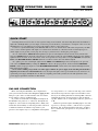
Rane SM 26B is a versatile audio device that combines the functionality of a 6-channel mixer and a 2-to-6 channel splitter. As a mixer, it allows you to control the levels and panning of individual input signals and create a stereo mix. As a splitter, it lets you distribute one or both input signals to up to six outputs, with adjustable levels and panning for each output. With its flexible connectivity options and balanced inputs and outputs, the SM 26B is ideal for a wide range of audio applications, including live sound reinforcement, studio recording, and home theater setups.
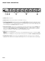
Rane SM 26B is a versatile audio device that combines the functionality of a 6-channel mixer and a 2-to-6 channel splitter. As a mixer, it allows you to control the levels and panning of individual input signals and create a stereo mix. As a splitter, it lets you distribute one or both input signals to up to six outputs, with adjustable levels and panning for each output. With its flexible connectivity options and balanced inputs and outputs, the SM 26B is ideal for a wide range of audio applications, including live sound reinforcement, studio recording, and home theater setups.


-
 1
1
-
 2
2
-
 3
3
-
 4
4


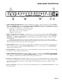
Rane SM 26B is a versatile audio device that combines the functionality of a 6-channel mixer and a 2-to-6 channel splitter. As a mixer, it allows you to control the levels and panning of individual input signals and create a stereo mix. As a splitter, it lets you distribute one or both input signals to up to six outputs, with adjustable levels and panning for each output. With its flexible connectivity options and balanced inputs and outputs, the SM 26B is ideal for a wide range of audio applications, including live sound reinforcement, studio recording, and home theater setups.
Ask a question and I''ll find the answer in the document
Finding information in a document is now easier with AI
