Kenwood KRF-V4070D Owner's manual

Category
AV receivers
Type
Owner's manual
1
EN
ITALIANO
DEUTSCH
FRANÇAIS
ENGLISH
ESPAÑOL
AUDIO VIDEO SURROUND RECEIVER
KRF-V5070D
KRF-V4070D
KRF-V5570D
INSTRUCTION MANUAL
KENWOOD CORPORATION
B60-5339-00 00 ID (E) 0211
This instruction manual is for some models. Model availability and features
(functions) may differ depending on the country and sales area.
About the supplied remote control
Compared to standard remote controls, the remote control supplied with this receiver has several
operation modes. These modes enable the remote control to control other audio/video components. In
order to effectively use the remote control it is important to read the operating instructions and obtain a
proper understanding of the remote control and how to switch its operation modes (etc.).
Using the remote control without completely understanding its design and how to switch the operation
modes may result in incorrect operations.
*5339/01-08/EN 10/1/03, 8:34 PM1
2
EN
ENGLISH
Before applying the power
Caution : Read this page carefully to ensure safe
operation.
How to use this manual
This manual is divided into four sections, Preparations, Operations,
Remote Control, and Additional Information.
Preparations
Shows you how to connect your audio and video components to the
receiver and prepare the surround processor.
Since this receiver works with all of your audio and video components,
we will guide you in setting up your system to be as easy as possible.
Operations
Shows you how to operate the various functions available on the
receiver.
Remote Control
Shows you how to operate other components using the remote control,
as well as a detailed explanation of all remote control operations. Once
you have registered your components with the proper setup codes, you’ll
be able to operate both this receiver and your other AV components (TV,
VCR, DVD player, CD player, etc.) using the remote control supplied with
this receiver.
Additional Information
Shows you additional information such as “In case of difficulty”
(troubleshooting) and “Specifications”.
Safety precautions
WARNING :
TO PREVENT FIRE OR ELECTRIC SHOCK,
DO NOT EXPOSE THIS APPLIANCE TO
RAIN OR MOISTURE.
Maintenance of the unit
When the front panel or case becomes dirty, wipe with a soft, dry
cloth. Do not use thinner, benzine, alcohol, etc. for these agents may
cause discoloration.
In regard to contact cleaner
Do not use contact cleaner because it could cause a malfunction. Be
specially careful not to use contact cleaners containing oil, for they
may deform the plastic component.
CAUTION
RISK OF ELECTRIC SHOCK
DO NOT OPEN
CAUTION: TO REDUCE THE RISK OF ELECTRIC SHOCK, DO NOT
REMOVE COVER (OR BACK). NO USER-SERVICEABLE PARTS
INSIDE. REFER SERVICING TO QUALIFIED SERVICE PERSONNEL.
THE LIGHTNING FLASH WITH ARROWHEAD SYMBOL,
WITHIN AN EQUILATERAL TRIANGLE, IS INTENDED TO
ALERT THE USER TO THE PRESENCE OF UNINSULATED
“DANGEROUS VOLTAGE” WITHIN THE PRODUCT’S
ENCLOSURE THAT MAY BE OF SUFFICIENT MAGNITUDE
TO CONSTITUTE A RISK OF ELECTRIC SHOCK TO
PERSONS.
THE EXCLAMATION POINT WITHIN AN EQUILATERAL
TRIANGLE IS INTENDED TO ALERT THE USER TO THE
PRESENCE OF IMPORTANT OPERATING AND
MAINTENANCE (SERVICING) INSTRUCTIONS IN THE
LITERATURE ACCOMPANYING THE APPLIANCE.
Memory back up function
Please note that the following items will be deleted from the unit's
memory if the power cord is disconnected from the AC outlet for
approximately 1 day.
Power mode. SUBWOOFER ON/OFF.
Input selector settings. SW RE-MIX ON/OFF.
Picture output. • Distance setting.
Speaker ON/OFF. Input mode setting.
Volume level. Midnight mode setting.
BASS, TREBLE, INPUT level. • PRO LOGIC II mode setting.
TONE ON/OFF. Broadcast band.
LOUDNESS ON/OFF. Frequency setting.
Dimmer level. Preset stations.
MD/TAPE settings. Tuning mode.
Listen mode setting. ACTIVE EQ mode.
SP SYSTEM. DSP mode.
Speaker settings.
Units are designed for operation as follows.
U.S.A. and Canada ........................................... AC 120 V only
Australia ........................................................... AC 240 V only
Europe and U.K. ............................................... AC 230 V only
China and Russia ............................................. AC 220 V only
Other countries .......... AC 110-120 / 220-240 V switchable*
*5339/01-08/EN 10/1/03, 8:34 PM2
3
EN
ENGLISH
Before applying the power .............................. 2
Safety precautions ............................................. 2
How to use this manual ..................................... 2
Unpacking .......................................................... 4
Preparing the remote control ............................ 4
Special features ................................................. 5
Names and functions of parts ......................... 6
Main Unit ........................................................... 6
Remote control unit (RC-R0627)
(KRF-V5070D) ..................................................... 7
Remote control unit (RC-R0628) (KRF-V4070D/
V5570D) ............................................................. 8
Setting up the system ........................................ 9
Connecting audio components ........................ 10
Connecting video components ........................ 11
Digital connections .......................................... 12
Connecting a DVD player (6-channel input)
(For KRF-V5070D only) .................................... 13
Connecting the speakers ................................. 14
Connecting the terminals ................................ 15
Connecting the antennas ................................. 15
Connecting the system control ....................... 16
Preparing for surround sound ....................... 17
Speaker settings .............................................. 17
Normal playback.............................................. 19
Preparing for playback ..................................... 19
Listening to a source component .................... 19
Adjusting the sound ......................................... 20
Recording .......................................................... 21
Recording audio (analog sources) ................... 21
Recording video ............................................... 21
Recording audio (digital sources) .................... 21
Listening to radio broadcasts ....................... 22
Tuning (non-RDS) radio stations ...................... 22
Using RDS (Radio Data System) ..................... 22
Presetting radio stations manually .................. 23
Receiving preset stations ................................ 23
Receiving preset stations in order (P.CALL) ... 23
Using the RDS DISPLAY key ........................... 24
Presetting RDS stations (RDS AUTO
MEMORY) ........................................................ 24
Tuning by Program TYpe (PTY search) ............ 25
Ambience effects ............................................. 26
Surround modes .............................................. 26
Surround play ................................................... 28
DVD 6-channel playback
(For KRF-V5070D only) .................................... 29
Convenient functions ....................................... 29
Contents
Caution : Read the pages marked carefully to ensure
safe operation.
Before applying the power
Preparations
Operations
Remote
Control
Additional
Information
Basic remote control operations for other
components ....................................................... 31
DVD player operation keys .............................. 31
CASSETTE deck, CD player & MD recorder
operations ........................................................ 32
In case of difficulty.......................................... 33
Specifications .................................................. 35
*5339/01-08/EN 10/1/03, 8:34 PM3
4
EN
ENGLISH
Before applying the power
6 m
POWER
Operation
When the STANDBY indicator is lit, the power turns ON when you press
the POWER
key on the remote control. When the power comes ON,
press the key you want to operate.
When pressing more than one remote control key successively,
press the keys securely by leaving an interval of 1 second or more
between keys.
Notes
1. The supplied batteries may have shorter lives than ordinary batteries
due to use during operation checks.
2. When the remote-controllable distance gets shorter than before,
replace both batteries with new ones.
3. Placing the remote sensor in direct sunlight, or in direct light from a
high frequency fluorescent lamp may cause a malfunction.
In such a case, change the location of the system installation to
prevent malfunction.
Preparing the remote control
Loading the batteries
1 Remove the cover. 2 Insert the batteries.
3 Close the cover.
Insert two AA-size (R6) batteries as indicated by the polarity markings.
Operating range
(Approx.)
Remote sensor
Infrared ray system
1
2
Unpacking
Unpack the unit carefully and make sure that all accessories are present.
FM indoor antenna (1) AM loop antenna (1)
For KRF-V5070D
Remote control unit (1) Batteries (R6/AA) (2)
RC-R0627
For KRF-V4070D and KRF-V5570D
Remote control unit (1) Batteries (R6/AA) (2)
RC-R0628
If any accessories are missing, or if the unit is damaged or fails to operate,
notify your dealer immediately. If your unit was shipped to you directly,
notify your shipper immediately. Kenwood recommend that you retain
the original carton and packing materials in case you needs to move or
ship the unit in the future.
Keep this manual handy for future reference.
*5339/01-08/EN 10/1/03, 8:34 PM4
5
EN
ENGLISH
Before applying the power
Special features
True home theater sound
This receiver incorporates a wide variety of surround modes to bring you
maximum enjoyment from your video software. Select a surround mode
according to your equipment or the software you are going to play and
enjoy! §
Dolby Digital
The DOLBY DIGITAL mode lets you enjoy full digital surround from
software processed in the Dolby Digital format. Dolby Digital provides up
to 5.1 channels of independent digital audio for better sound quality and
more powerful presence than conventional Dolby Surround.
Dolby PRO LOGIC
II
DOLBY PRO LOGIC II, whilst totally compatible with its predecessor
PRO LOGIC, provides greater advantages in surround sound. It allows
user to enjoy the conventional stereo or Dolby Surround with a convincing
“5.1 like” presentation. PRO LOGIC II offers special features for controlling
the overall spatial, dimensionality and frontal sound field imaging. PRO
LOGIC II produces an impressive surround sound from video software
marked
and three-dimensional space from music CD.
When listening to music, you will be able to enjoy the experience of sheer
STEREO surround sound.
DTS
DTS (Digital Theater System) is a 5.1 channel digital audio format that
provides five full-spectrum channels and one low-frequency (subwoofer)
channel for unprecedented clarity, optimum channel separation and a
(wide) dynamic range.
In the DTS mode, the 5.1 channel digital input from a DTS CD, LD or DVD
disc (carrying the “DTS” marking) can be played in Digital Surround.
Important:
When a DTS disc is played on a CD, LD or DVD player, noise may be
output from the analog output. It is recommended that you connect the
digital output of the player to the digital input of this unit.
DSP surround modes
The DSP (Digital Signal Processor) used for this receiver incorporates a
variety of high quality adjustable sound fields, like “ARENA”, “JAZZ
CLUB”, THEATER”, STADIUM” and “DISCO”. It is compatible with
almost any kind of program source.
DVD 6-channel input (For KRF-V5070D only)
If you own a DVD player equipped with 6-channel output, this receiver
allows you to obtain the full surround sound impact of DVD source
material featuring multi-channel encoding. Since the source signals are
digital and each channel is input independently, the resulting ambience
is far superior to what can be achieved with conventional surround sound
systems.
ACTIVE EQ
ACTIVE EQ mode will produce a more dynamic sound quality in any
condition. You can enjoy a more impressive sound effect when ACTIVE
EQ is turned on during Dolby Digital and DTS playback.
IR (InfraRed) remote control
In addition to the basic receiver opeations, this IR remote control
supplied can also operate Kenwood cassette deck, MD recorder or CD
player which are connected using the system control cords.
This remote control can also control Kenwood DVD players directly
without using the DVD players' remote control.
RDS (Radio Data System) tuner
The receiver is equipped with an RDS tuner that provides several
convenient tuning functions: RDS Auto Memory, to automatically preset
up to 40 RDS stations broadcasting different programs; station name
display, to show you the name of the current broadcast station; and PTY
search to let you tune stations by program type.
PTY (Program TYpe) search
Tune the stations by specifying the type of program you want to hear.
*5339/01-08/EN 10/1/03, 8:34 PM5
6
EN
ENGLISH
AB
POWER
STANDBY
DIMMER
SPEAKERS ON
OFF
PHONES
ACTIVE EQ
LISTEN MODE
INPUT MODE BAND AUTO MEMORY
ACTIVE EQ DTS
DOLBY DIGITAL
SOUND
SETUP
MULTI CONTROL INPUT SELECTOR
DOWN
MUTE
UP
VOLUME CONTROL
ON OFF
ON
STANDBY
Names and functions of parts
1 POWER ON/OFF key &
Use to turn the main power ON/OFF.
2 ON/STANDBY
key &
Use to switch the power ON/STANDBY when
the POWER is turned ON.
STANDBY indicator
3 DIMMER key
Use to select the REC MODE. ¡
Use to adjust the brightness of the display.
º
4 LISTEN MODE key
Use to select the listening mode.
5 Surround LED (light-emitting diode)
indicators
ACTIVE EQ mode LED indicator )
Lights when the receiver is in the ACTIVE EQ
mode.
DTS mode LED indicator
Lights when the receiver is in the DTS mode.
DOLBY DIGITAL mode LED indicator
Lights when the receiver is in the Dolby
Digital mode.
6 SOUND key ª
Use to adjust the sound quality and the
ambience effects.
7 MULTI CONTROL knob &
Use to control a variety of settings.
8 INPUT SELECTOR knob (
Use to select the input sources.
9 VOLUME CONTROL knob (
0 PHONES jack )
Use for headphone listening.
! SPEAKERS ON/OFF key (
Use to turn the speakers ON/OFF.
@ ACTIVE EQ key )
Use to select ACTIVE EQ setting.
# INPUT MODE key 9
Use to switch between full auto, digital and
analog inputs.
$ BAND key
Use to select the broadcast band.
% AUTO key
Use to change “TAPE” indication to “MD”.
(
Use to select the auto tuning mode.
^ MEMORY key £
Use to store radio stations in the preset
memory.
& SETUP key &
Use to select the speakers' settings etc.
* MUTE key )
Use to temporarily mute the sound.
Main Unit
Standby mode
While the standby indicator is lit, a small amount of power is supplied to
the system to back-up the memory. This is called standby mode. Under
the condition, the system can be turned ON by the remote control unit.
Display
Speaker selection indicators
Input channel indicators
Output channel indicators
Band indicators
STEREO indicator
Frequency display,
Input display,
Preset channel display,
Surround mode display
Speaker indicator
PRO LOGIC
indicator
AUTO DETECT
indicator
DOLBY DIGITAL
indicator
DTS indicator
CLIP indicator
AUTO indicator
MEMO. indicator
ST. indicator
TUNED indicator
MUTE indicator
TONE indicator
LOUDNESS indicator
96kHzfs indicator
DSP indicator
DIGITAL indicator
RDS indicators
6CH INPUT indicator
Connection at POWER ON/OFF key
The power in this equipment will not be completely cut off from the AC
wall outlet when the main switch is turned OFF.
*5339/01-08/EN 10/1/03, 8:34 PM6
7
EN
ENGLISH
Names and functions of parts
Remote control unit (RC-R0627) (KRF-V5070D)
1
DISC SKIP
BASS BOOST
AUTO
PHONO
CD/DVD
DVD
TUNER
MD/TAPE
VIDEO1 VIDEO2
23
POWER
DVD
POWER
RECEIVER
MENU
P.CALL
TUNING
MUTE
VOLUME
A/B+100
ENTER
BAND
P.CALL
MULTI CONTROL
456
789
0+10
SETUP
OSD
SOUND
RETURN
LISTEN MODE
DVD/6CH
DISC SEL.
ACTIVE EQ
LOUDNESS
TOP MENU
RDS DISPLAY
TONE
PTY
DOWN-PAGE-UP
1 Numeric keys £
If CD or MD is selected as the input source,
these keys function as numeric keys. If tuner
is selected as the input source, these keys
are used to call up station presets.
2 DOWN-PAGE- key
Use to operate the DVD component.
LOUDNESS key )
Use to switch the status of LOUDNESS.
3 MENU key
Use to operate the DVD component.
SETUP key &
Use to select the speakers' settings etc.
4 OSD (On Screen Display) key
Use to operate the DVD component.
SOUND key ª
Use to adjust the sound quality and ambience
effects.
5 MULTI CONTROL %/ keys &
Use to control a variety of settings.
Use to operate other components.
P.CALL 4/¢ keys £
If tuner is selected as the input source, these
keys function as preset channel call keys.
4/¢ keys
If CD or MD is selected as the input source,
these keys function as skip keys.
6 TUNING 1/¡ keys
Use to operate the tuner or selected
component.
If CD, MD or TAPE is selected as the input
source, these keys function as search keys.
7 A/B key
If TAPE is selected as the input source, this is
A and B deck of a double cassette deck.
+100 key
Use to select the disc number with the multi-
CD player.
DISC SKIP key
If CD is selected as the input source, this key
functions as the multi-CD player disc skip
key.
8 BASS BOOST key )
Use to select the maximum adjustment
setting for the low frequency range.
9 Input Selector keys (DVD/6CH, PHONO,
CD/DVD, TUNER, MD/TAPE, VIDEO 1,
VIDEO 2) (
Use to select the input sources.
4 DVD ¢ keys
When in DVD player operations, these keys
function as skip keys.
0 DISC SEL. key
Use to operate other components.
ACTIVE EQ key )
Use to select ACTIVE EQ setting.
! MUTE key )
Use to temporarily mute the sound.
@ POWER
key
Use to turn the receiver on and off.
# DVD POWER key
Use to turn on the DVD equipment.
$ RECEIVER key
Use to return to the operation of the receiver.
% -PAGE-UP key
Use to operate the DVD component.
PTY key
Use for PTY search.
^ TOP MENU key
Use to operate the DVD component.
RDS DISPLAY key ¢
Use for RDS function.
& RETURN key
Use to operate the DVD component.
LISTEN MODE key
Use to select the listening mode.
* ENTER key
Use to operate other components.
2 key
Use to operate other components.
( BAND key
Use to select the broadcast band.
6 key
If CD is selected as the input source, this key
functions as the play/pause key.
If MD or TAPE is selected as the input source,
this key functions as the play key.
) 8 key
Use to operate other components.
¡ AUTO key
Use to select the auto tuning mode.
7 key
If CD, MD or TAPE is selected as the input
source, this key functions as the stop key.
TONE key )
Use to switch the status of TONE control.
£ VOLUME keys (
Use to adjust the receiver volume.
If the name of a function is different on
the receiver and on the remote control,
the name of the remote control key in
this manual is indicated in parentheses.
*5339/01-08/EN 10/1/03, 8:34 PM7
8
EN
ENGLISH
Names and functions of parts
Remote control unit (RC-R0628) (KRF-V4070D/V5570D)
1
DISC SKIP
BASS BOOST
AUTO
AUX CD/DVD
DVD
TUNER
MD/TAPE
VIDEO1 VIDEO2
23
POWER
DVD
POWER
RECEIVER
MENU
P.CALL
TUNING
MUTE
VOLUME
A/B+100
ENTER
BAND
P.CALL
MULTI CONTROL
456
789
0+10
SETUP
OSD
SOUND
RETURN
LISTEN MODE
DVD
DISC SEL.
ACTIVE EQ
LOUDNESS
TOP MENU
RDS DISPLAY
TONE
PTY
DOWN-PAGE-UP
1 Numeric keys £
If CD or MD is selected as the input source,
these keys function as numeric keys. If tuner
is selected as the input source, these keys
are used to call up station presets.
2 DOWN-PAGE- key
Use to operate the DVD component.
LOUDNESS key )
Use to switch the status of LOUDNESS.
3 MENU key
Use to operate the DVD component.
SETUP key &
Use to select the speakers' settings etc.
4 OSD (On Screen Display) key
Use to operate the DVD component.
SOUND key ª
Use to adjust the sound quality and ambience
effects.
5 MULTI CONTROL %/ keys &
Use to control a variety of settings.
Use to operate other components.
P.CALL 4/¢ keys £
If tuner is selected as the input source, these
keys function as preset channel call keys.
4/¢ keys
If CD or MD is selected as the input source,
these keys function as skip keys.
6 TUNING 1/¡ keys
Use to operate the tuner or selected
component.
If CD, MD or TAPE is selected as the input
source, these keys function as search keys.
7 A/B key
If TAPE is selected as the input source, this is
A and B deck of a double cassette deck.
+100 key
Use to select the disc number with the multi-
CD player.
DISC SKIP key
If CD is selected as the input source, this key
functions as the multi-CD player disc skip
key.
8 BASS BOOST key )
Use to select the maximum adjustment
setting for the low frequency range.
9 Input Selector keys (DVD, AUX, CD/DVD,
TUNER, MD/TAPE, VIDEO 1, VIDEO 2)(
Use to select the input sources.
4 DVD ¢ keys
When in DVD player operations, these keys
function as skip keys.
0 DISC SEL. key
Use to operate other components.
ACTIVE EQ key )
Use to select ACTIVE EQ setting.
! MUTE key )
Use to temporarily mute the sound.
@ POWER
key
Use to turn the receiver on and off.
# DVD POWER key
Use to turn on the DVD equipment.
$ RECEIVER key
Use to return to the operation of the receiver.
% -PAGE-UP key
Use to operate the DVD component.
PTY key
Use for PTY search.
^ TOP MENU key
Use to operate the DVD component.
RDS DISPLAY key ¢
Use for RDS function.
& RETURN key
Use to operate the DVD component.
LISTEN MODE key
Use to select the listening mode.
* ENTER key
Use to operate other components.
2 key
Use to operate other components.
( BAND key
Use to select the broadcast band.
6 key
If CD is selected as the input source, this key
functions as the play/pause key.
If MD or TAPE is selected as the input source,
this key functions as the play key.
) 8 key
Use to operate other components.
¡ AUTO key
Use to select the auto tuning mode.
7 key
If CD, MD or TAPE is selected as the input
source, this key functions as the stop key.
TONE key )
Use to switch the status of TONE control.
£ VOLUME keys (
Use to adjust the receiver volume.
If the name of a function is different on
the receiver and on the remote control,
the name of the remote control key in
this manual is indicated in parentheses.
*5339/01-08/EN 10/1/03, 8:34 PM8
9
EN
ENGLISH
Setting up the system
Make connections as shown in the following pages.
When connecting the related system components, be sure
to refer to the instruction manuals supplied with the
components you are connecting.
Do not connect the power cord to a wall outlet until all
connections are completed.
Notes
1. Be sure to insert all connection cords securely. If their connections are
imperfect, the sound may not be produced or there will be noise
interference.
2. Be sure to remove the power cord from the AC outlet before plugging
or unplugging any connection cords. Plugging/unplugging connection
cords without disconnecting the power cord can cause malfunctions
and may damage the unit.
3. Do not connect power cords from components whose power
consumption is larger than what is indicated on the AC outlet at the
rear of this unit.
Analog connections
Audio connections are made using RCA pin cords. These cables transfer
stereo audio signal in an “analog” form. This means the audio signal
corresponds to the actual audio of two channels. These cables usually
have 2 plugs at each end, red for the right channel and white for the left
channel. These cables are usually packed together with the source unit,
or are available at your local electronics retailer.
Microcomputer malfunction
If operation is not possible or an erroneous display appears, even
though all connections have been made properly, reset the
microcomputer by referring to “In case of difficulty”.
Input mode settings
CD/DVD, VIDEO2 and DVD or DVD/6CH (KRF-V5070D only) inputs
each include jacks for digital audio input and analog audio input.
After completing connections and turning on the receiver, follow the
steps below.
1 Use the INPUT SELECTOR knob to select CD/DVD, VIDEO2,
DVD or DVD/6CH (KRF-V5070D only).
2 Press the INPUT MODE key.
Each press switches the setting as follows:
In DTS play mode
1 F-AUTO (digital input, analog input)
2 D-MANUAL (digital input)
In CD/DVD, VIDEO2, DVD or DVD/6CH (KRF-V5070D only)
play mode
1 F-AUTO (digital input, analog input)
2 D-MANUAL (digital input)
3 6CH INPT (DVD/6CH input)
4 ANALOG (analog input)
Digital input:
Select this setting to play digital signals from a DVD, CD, or LD
player.
Analog input:
Select this setting to play analog signals from a cassette deck, VCR,
or record player.
Auto detect:
In “F-AUTO” (full auto) mode (AUTO DETECT and DIGITAL
indicators light up), the receiver detects the digital or analog input
signals automatically. Priority is given to digital signal during input
mode selection. The receiver will select the input mode and listening
mode automatically during playback to match the type of input
signal (Dolby Digital, PCM, DTS ) and the speaker setting. The initial
factory setting is full auto.
To keep the receiver set to the currently selected listening mode,
use the INPUT MODE key to select “D-MANUAL” (digital manual).
However, even when this setting is selected, there may be cases
in which the listening mode is selected automatically to match a
Dolby Digital source signal depending on the combination of listening
mode and source digital.
In D-MANUAL mode, if the audio reproduction stops in the middle
due to change in the input signals, etc, press the LISTEN MODE
key.
If the INPUT MODE key is pressed quickly, sound may not be
produced. Press the INPUT MODE key again.
INPUT MODE
INPUT SELECTOR
LISTEN MODE
*5339/09-16/EN 10/1/03, 8:34 PM9
10
EN
ENGLISH
+
-
+
-
PHONO
GND
CD/DVD
REC OUT PLAY IN
VIDEO1
REC OUT PLAY IN
MD / TAPE
L
R
AUX
R
L
AUDIO
Setting up the system
Connecting audio components
IN
OUTIN
OUT
OUT
OUT
To AC wall outlet
SYSTEM CONTROL
jacks ^
Record player
Cassette deck or MD recorder
CD or DVD player
Video component ¡
Moving coil (MC) cartridge
record player cannot be used
directly from the receiver unit. It
can only be used when another
equalizer amplifier is connected.
(For KRF-V5070D only)
(For KRF-V4070D/
V5570D)
Shape of AC outlets
U.K.
EUROPE
*5339/09-16/EN 10/1/03, 8:34 PM10
11
EN
ENGLISH
+
-
+
-
PLAY IN
VIDEO 2
DVDREC OUT PLAY IN
VIDEO 1
VIDEO 2
IN
DVD
IN
MONITOR
OUT
VIDEO 1
OUT
VIDEO 1
IN
VIDEO
AUDIO
Setting up the system
Connecting video components
Video inputs and outputs
(Yellow RCA pin cords)
Audio inputs
and outputs
OUT OUT
Monitor TV
Video inputs
(Yellow RCA pin cords)
VIDEO
IN
A video component with digital audio outputs should be connected to the VIDEO 2 jacks.
Video deck
IN IN
OUT
OUT
OUT OUT
Video
IN/OUT
Audio
IN/OUT
DVD player or LD player
For KRF-V4070D/
V5570D only
*5339/09-16/EN 10/1/03, 8:34 PM11
12
EN
ENGLISH
+
-
+
-
VIDEO 2
DVD
CD / DVD
COAXIAL OPTICAL
DIGITAL IN
Setting up the system
Digital connections
The digital in jacks can accept DTS, Dolby Digital, or PCM signals. Connect components capable of outputting DTS, Dolby Digital, or standard PCM (CD)
format digital signals.
If you have connected any digital components to the receiver, be sure to read the “Input mode settings” section carefully. 9
Component with DTS,
Dolby Digital, or PCM
COAXIAL DIGITAL OUT
COAXIAL
DIGITAL
OUT
(AUDIO)
DOLBY DIGITAL RF
OUT (AUDIO)
LD player
PCM OUT
RF digital
demodulator
(DEM-9991D)
(sold separately)
CD or DVD player
OPTICAL DIGITAL OUT (AUDIO)
Optical fiber cable
COAXIAL DIGITAL OUT
(AUDIO)
Connect the video signal and analog
audio signals to the VIDEO 2 jacks.
(See “Connecting video components”.)
!
To connect an LD player with a DIGITAL RF OUT, connect the LD player to the KENWOOD RF digital demodulator (DEM-9991D).
Next, connect the DIGITAL OUT jacks of the demodulator to the DIGITAL IN jacks of the receiver.
Connect the video signal and analog audio signals to the VIDEO 2 jacks. (See “Connecting video components”.)
*5339/09-16/EN 10/1/03, 8:34 PM12
13
EN
ENGLISH
+
-
+
-
CENTER
SUB
WOOFER
SURROUND
FRONT
VIDEO 1
OUT
VIDEO 1
IN
VIDEO 2
IN
DVD
IN
MONITOR
OUT
VIDEO 2
DVD/6CH
CD / DVD
COAXIAL OPTICAL
DVD / 6CH INPUT
VIDEO
DIGITAL IN
Setting up the system
Connecting a DVD player (6-channel input)
(For KRF-V5070D only)
CAUTION
Be sure to adhere to the following, or proper ventilation will be blocked causing damage or fire hazard.
Do not place any object impairing heat radiation onto the top of the unit.
Leave a space around the unit (from the largest outside dimension including projection) equal or greater than, shown below.
Top panel : 50 cm Side panel : 10 cm Back panel : 10 cm
If you have connected a DVD player to the receiver with digital connection, be sure to read the “Input mode settings” section carefully. 9
SURROUND
OUT L/R
VIDEO OUT
(Yellow RCA
pin cord)
DVD player
SUBWOOFER
OUT
CENTER OUT
FRONT
OUT L/R
COAXIAL
DIGITAL
OUT
(AUDIO)
*5339/09-16/EN 10/1/03, 8:34 PM13
14
EN
ENGLISH
+
-
+
-
CENTER
FRONT
+
-
CR L
RED WHITE GREEN
KRF-V5070D/KRF-V4070D
SURROUND
+
-
R
GRAY
L
BLUE
SUB
WOOFER
SURROUND
+
-
KRF-V5570D
R
GRAY
L
BLUE
SW
PURPLE
SPEAKERS (6
SPEAKERS (6-16)
SPEAKERS (6-16)
SUB WOOFER
PRE OUT
Setting up the system
Connecting the speakers
Center
Speaker
Front Speakers
Right Left
Sub woofer
Powered
sub woofer
(KRF-V5070D/
V4070D)
Right Left
(Be sure to connect both
surround speakers)
Surround Speakers
*5339/09-16/EN 10/1/03, 8:34 PM14
15
EN
ENGLISH
1 Strip coating.
2 Push the lever.
3 Insert the cord. 4 Return the lever.
+
-
+
-
GND
AM
ANTENNA
FM
75
Setting up the system
Connecting the terminals
Speaker impedance
After confirming the speaker impedance indications printed on the
rear panel of the receiver, connect speakers with matching impedance
ratings. Using speakers with a rated impedance other than that
indicated on the rear panel of the receiver could result in malfunctions
or damage to the speakers or receiver.
Never short circuit the + and – speaker cords.
If the left and right speakers are connected inversely or the speaker
cords are connected with reversed polarity, the sound will be
unnatural with ambiguous acoustic imaging. Be sure to connect the
speakers correctly.
Connecting the antennas
AM loop antenna
The supplied loop antenna is for use indoors. Place it as far as possible
from the receiver, TV set, speaker cords and power cord, and adjust
the direction for best reception.
FM indoor antenna
The supplied indoor antenna is for temporary use only. For stable
signal reception we recommend using an outdoor antenna. Disconnect
the indoor antenna when you connect one outdoors.
FM outdoor antenna
Lead the 75 coaxial cable connected to the FM outdoor antenna into
the room and connect it to the FM 75 terminal.
AM antenna terminal connections
1 Push lever. 2 Insert cord. 3 Release lever.
FM antenna terminal connections
Insert cord.
Use an antenna
adapter
(Commercially
available)
Attach to the
stand
AM loop antenna
FM indoor antenna
FM outdoor antenna
*5339/09-16/EN 10/1/03, 8:34 PM15
16
EN
ENGLISH
Speaker placement
Front speakers : Place to the front left and right of the listening
position. Front speakers are required for all surround modes.
Center speaker : Place front and center. This speaker stabilizes the
sound image and helps recreate sound motion. Required for surround
playback.
Surround speakers : Place to the direct left and right, or slightly
behind, the listening position at even heights, approximately 1 meter
above the ears of the listeners. These speakers recreate sound
motion and atmosphere. Required for surround playback.
Subwoofer : Reproduces powerful deep bass sounds.
Although the ideal surround system consists of all the speakers
listed above, if you don't have a center speaker or a subwoofer, you
can divide those signals between the available speakers in the
speaker settings steps to obtain the best possible surround
reproduction from the speakers you have available. &
Receiver
Cassette deck
or MD recorder
CD player
Record player
Connecting system control cords after connecting a KENWOOD
audio component system lets you take advantage of convenient
system control operations.
This unit is compatible only with the [SL-16] mode. The system
control operation is not available if the unit is connected in the
[XS8], [XS], or [XR] connection mode.
If your component has the mode select switch, set the connected
components to the [SL16] mode.
You may connect the system control cord to either the up or down
jack.
EXAMPLE: [SL16] mode connections
The underlined portion represents the setting of the system control
mode.
In order to take advantage of the system control operations, the
components must be connected to the correct jacks. To use a CD
player it must be connected to the CD jacks. To use a cassette deck
(or MD recorder) it must be connected to the MD/TAPE jacks.
When using more than one CD player (etc.) only the one connected
to the specified jacks may be connected for system control.
Some CD players and cassette decks are not compatible with the
[SL16] system control mode. Do not make system connections
with equipment that is not [SL16] compatible.
Some MD players are not system control compatible. You cannot
make system control connections to this kind of equipment.
Notes
1. [SL16] equipment cannot be combined with [XR], [XS], and [XS8]
equipment for system operations. If your equipment consists of
this kind of combination, please do not connect any system control
cords. Even without system control cords, normal operations can
be carried out without affecting performance.
2. Do not connect system control cords to any components other
than those specified by KENWOOD. It may cause a malfunction
and damage your equipment.
3. Be sure the system control plugs are inserted all the way in to the
system control terminals.
Connecting the system control
Setting up the system
SYSTEM CONTROL
cord
SYSTEM CONTROL OPERATIONS
Remote Control
Lets you operate this unit with the system remote supplied with the
receiver.
Automatic Operation
When you start playback from a source component, the input selector
on this unit switches to that component automatically.
Synchronized Recording
Lets you synchronize recording with the start of playback when
recording from CD, MD or analog discs.
S
Y
S
TEM
CO
NTR
OL
SYSTEM
CONTROL
cord
[
SL16]
[
SL16] [XS] [XS8] [XR]
[
SL16] [XS] [XS8]
[XS]
Front
speaker
Subwoofer
Surround
speaker
Center speaker
Listening
position
*5339/09-16/EN 10/1/03, 8:34 PM16
17
EN
ENGLISH
Preparing for surround sound
Speaker settings
To enable you to obtain optimum enjoyment from the receiver’s listening
modes, make sure to complete the speaker settings (subwoofer, front,
center, and surround speakers) as described below.
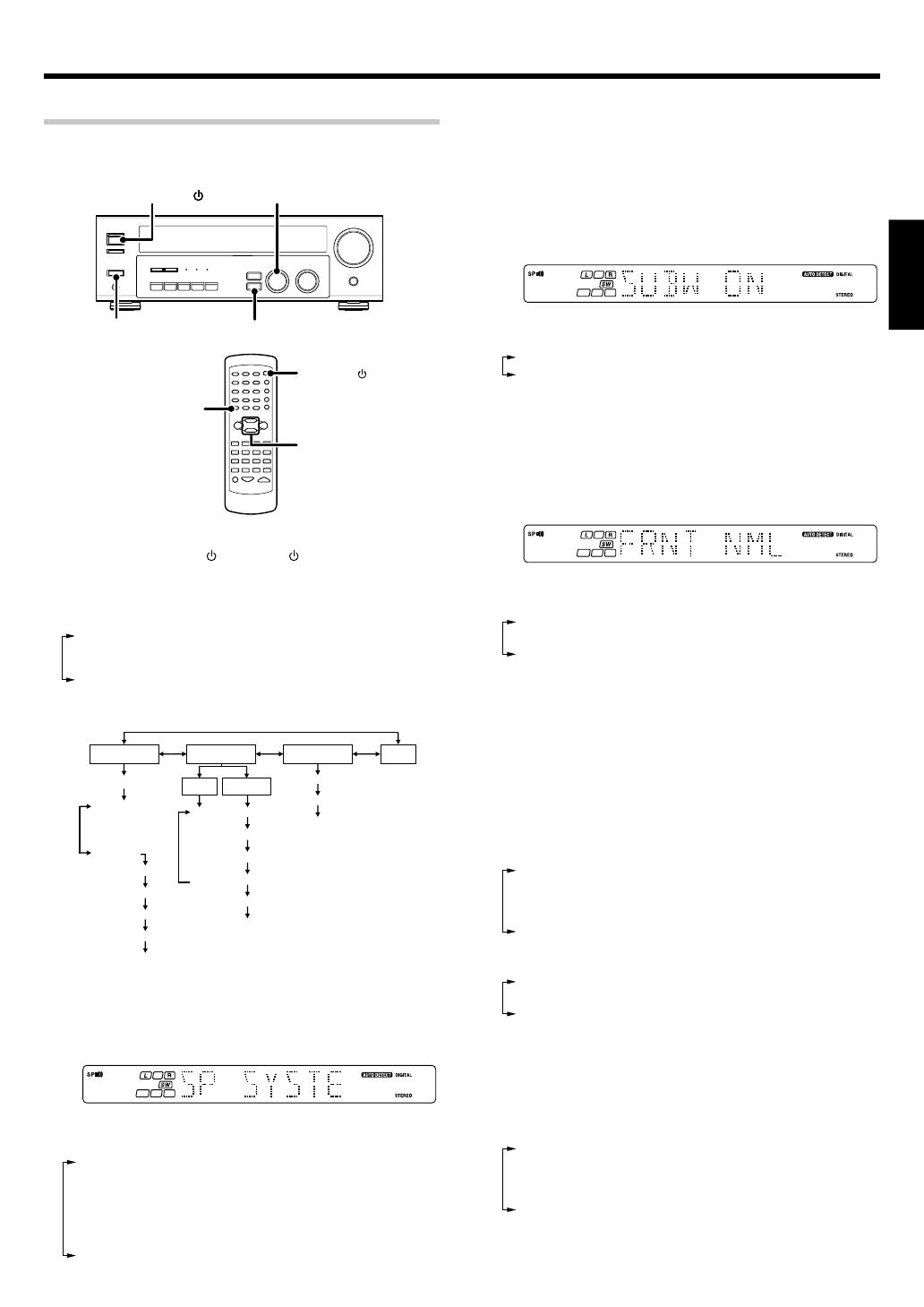
1
Turn on the power to this receiver by pressing POWER ON/
OFF and ON/STANDBY
or POWER key.
2
Press the SETUP key to enter the SETUP mode and use the
MULTI CONTROL knob or keys for the following displays.
1 SP SETUP
2 TESTTONE
3 DISTANCE
4 EXIT
The flow of the SETUP is as follows;
SP SETUP TESTTONE DISTANCE EXIT
Front
Center
Surround
SP System
L
C
R
SR
SL
SW
L
C
R
SR
SL
SW
MANUAL
AUTO
Full Range
2Way 2Speaker
2Way 3Speaker
Others
Subwoofer
Front
Center
Surround
Subwoofer Re-mix
3
Select a speaker system.
1 Select SP SETUP and press the SETUP key again so that the
speaker system indication “SP SYSTEM” scrolls across the
display.
2 Use the MULTI CONTROL knob or keys to select the speaker
system setting.
1 FULL RANGE : For selected Kenwood speaker – for example,
KS-207HT.
2 2WAY 2SPKR : For selected Kenwood speaker – for example,
KS-307HT.
3 2WAY 3SPKR : For selected Kenwood speaker – for example,
KS-707HT.
4 OTHERS : For general speakers.
The selection of FULL RANGE, 2WAY 2SPKR or 2WAY 3SPKR
should only be used with 5 channels speaker system setting.
• When the setting FULL RANGE, 2WAY 2SPKR or 2WAY 3SPKR
is selected, the procedure skips to step 4.
3 For general speaker setting, use the MULTI CONTROL knob or
keys to select OTHERS and press the SETUP key again.
The subwoofer setting indication “SUBW ON” appears.
4 Use the MULTI CONTROL knob or keys to select the
appropriate subwoofer setting.
1 SUBW ON : Subwoofer setting mode to the receiver is ON.
2 SUBW OFF :
Subwoofer setting mode to the receiver is OFF.
The initial setting is “SUBW ON”.
When the setting “SUBW OFF” is selected, the front speakers
are automatically set to “FRNT LRG” and the procedure skips to
step 8.
Before step 8, press the SETUP key to accept the setting.
When subwoofer output sound is required, select “FRNT NML”.
5 Press the SETUP key to accept the setting.
The front speakers setting indication “FRNT NML” appears.
6 Use the MULTI CONTROL knob or keys to select the
appropriate front speakers setting.
1 FRNT NML (normal) : Average size front speakers are
connected to the receiver.
2 FRNT LRG (large) : Large front speakers are connected to
the receiver.
For “FRNT LRG” selection, no sound will be heard from subwoofer
speaker even when it is set to ON. However, if you select “SW
RE-MIX ON” when subwoofer is selected, you will be able to
hear sound from the subwoofer.
When in STEREO mode, the sound goes directly to front speaker.
7 Press the SETUP key to accept the setting.
The center speaker setting indication “CNTR NML” appears.
8 Use the MULTI CONTROL knob or keys to select the
appropriate center speaker setting.
If you have selected “LRG” as the front speakers setting,
1 CNTR NML (normal) : An average size center speaker is
connected to the receiver.
2 CNTR LRG (large) : A large center speaker is connected to
the receiver.
3 CNTR OFF : Center speaker setting mode to the
receiver is OFF.
If you have selected “NML” as the front speakers setting,
1 CNTR ON : Center speaker setting mode to the
receiver is ON.
2 CNTR OFF : Center speaker setting mode to the
receiver is OFF.
9 Press the SETUP key again to accept the setting.
•The surround speaker setting indication “SURR NML” appears.
0 Use the MULTI CONTROL knob or keys to select the
appropriate surround speaker setting.
If you have selected “LRG” as the center speaker setting,
1 SURR NML (normal) : Average size surround speakers are
connected to the receiver.
2 SURR LRG (large) : Large surround speakers are connected
to the receiver.
3 SURR OFF : Surround speaker setting mode to the
receiver is OFF.
MULTI CONTROL
SETUP
POWER ON/OFF
SETUP
MULTI
CONTROL
POWER
ON/STANDBY
Continued to next page
*5339/17-21/EN 10/1/03, 8:35 PM17
18
EN
ENGLISH
Preparing for surround sound
If you have selected other than “LRG” as the center speaker
setting,
1 SURR ON : Surround speaker setting mode to the receiver is
ON.
2 SURR OFF : Surround speaker setting mode to the receiver is
OFF.
! Press the SETUP key again to accept the setting.
The subwoofer re-mix setting indication “SW RE-MIX” scrolls
across the display.
If subwoofer is turned OFF, subwoofer re-mix setting is not
visible.
@ Use the MULTI CONTROL knob or keys to select the
appropriate subwoofer re-mix setting.
1 RMX ON : Subwoofer re-mix set mode to the receiver is ON.
2 RMX OFF : Subwoofer re-mix set mode to the receiver is OFF.
# Press the SETUP key to accept the setting.
The receiver enters the speaker volume level adjustment mode.
In step 4 and 5, indications appear only for the selected channels
of the speakers that require adjusting.
4
Adjust the speaker volume level.
From your usual listening position, adjust the volume levels. The
volume levels from each speaker should be the same.
1 Press the SETUP key to begin TEST TONE.
The selection of AUTO/MANUAL TEST TONE is done by the
MULTI CONTROL knob or keys.
1 AUTO
2 MANUAL
2 Press the SETUP key again to select either AUTO or MANUAL.
Use the MULTI CONTROL knob or keys to adjust the volume
level of the test tone output from the speaker channel to be
adjusted.
For AUTO selection, the test tone is heard from the speakers
in the following sequence for 2 seconds each:
If you change the volume level settings for the speakers while
listening to music, the settings referred to on this page are also
changed. ª
• If any of the speakers is set as OFF during SP SETUP, the TEST
TONE adjustment for that speaker will be skipped.
3 Press the SETUP key.
The test tone is turned off. The receiver enters the mode for
inputting the distance to the speakers.
4 For MANUAL selection, press the SETUP key each time to
select the speaker channel.
5
Input the distance to the speakers.
1 Select the DISTANCE from the set up displays and press the
SETUP key again.
2 Measure the distance from the listening position to each of
the speakers.
Jot down the distance to each of the speakers.
Distance to front speakers : ____ feet (meters)
Distance to center speaker : ____ feet (meters)
Distance to surround speakers : ____ feet (meters)
3 Use the MULTI CONTROL knob or keys to select the distance
to the front speakers.
The speaker indicator to be adjusted blinks.
Indication in feet Indication in meters
The allowable setting range is 1 to 30 feet (0.3m to 9.0m),
adjustable in 1 foot (0.3m) increments.
4 Press the SETUP key to accept the settings.
5 Repeat steps 3 and 4 to input the distance for each of the
speakers.
6 Setup is complete when the EXIT indication appears.
The speakers you have selected should appear on the display.
Confirm that all the speakers have been correctly selected.
7 Press the SETUP key to exit the SETUP mode.
Input level adjustment (analog sources only)
If the input level of an analog source signal is too high, the CLIP indicator
will blink to indicate the source signal. Adjust the input level.
1 Use the INPUT SELECTOR knob to select the source of which the
input level you want to adjust.
You can store a separate input level for each input source.
2 Press the SOUND key repeatedly until the “INPUT” indication
appears.
3 Use the MULTI CONTROL knob or keys to adjust the input level.
The input level may be adjusted to any one of three settings: 0dB,
-3dB, and -6dB. (The initial setting is 0dB.)
4 Press the SOUND key again to return to the input indication.
*5339/17-21/EN 11/1/03, 10:53 AM18
19
EN
ENGLISH
Listening to a source component
1
Use the INPUT SELECTOR knob or keys to select the source
you want to listen to.
The input sources change as shown below:
KRF-V4070D/V5570D
1 “AUX”
2 “TUNER”
3 “CD/DVD”
4 “TAPE” or “MD”
5 “VIDEO1”
6 “VIDEO2”
7 “DVD”
KRF-V5070D
1 “PHONO”
2 “TUNER”
3 “CD/DVD”
4 “TAPE” or “MD”
5 “VIDEO1”
6 “VIDEO2”
7 “DVD/6CH”
2
Start playback from the selected source.
3
Use the VOLUME CONTROL knob or VOLUME keys to adjust
the volume.
Normal playback
Some preparatory steps are needed before starting playback.
Turning on the receiver
1 Turn on the power to the related components.
2 Turn on the power to this receiver by pressing POWER ON/OFF
and ON/STANDBY
key.
Selecting the input mode
If you have selected a component connected to the CD/DVD, VIDEO2,
DVD or DVD/6CH (KRF-V5070D only) jacks, make sure that the input
mode setting is correct for the type of audio signal to be used. 9
Selecting MD/TAPE
Select the source name corresponding to the component connected to
the MD/TAPE jacks. The initial factory setting is “TAPE”. To change the
source to “MD”, follow the steps below:
1 Use the INPUT SELECTOR knob to select “TAPE”.
2 Hold down the AUTO key for more than 2 seconds.
The source indication changes to “MD”.
To return to the original indication, repeat procedure 2.
Setting the speaker status
Press the SPEAKERS ON/OFF key to switch the speaker on or off.
Preparing for playback
The speaker indicator lights up.
AUTO INPUT SELECTORPOWER
ON/OFF
SPEAKERS
ON/OFF
ON/STANDBY
INPUT SELECTOR
VOLUME CONTROL
Input
Selector
VOLUME
*5339/17-21/EN 10/1/03, 8:35 PM19
20
EN
ENGLISH
Normal playback
Adjusting the sound
Adjusting the TONE (remote control only)
You can adjust the sound quality when the receiver is in the PCM stereo
and analog stereo mode.
1 Press the TONE key to select the TONE mode.
2 Use the MULTI CONTROL knob or keys to select TONE ON/OFF.
3 When in TONE ON selection, press the TONE key for the following
displays.
BASS : Select this to adjust the low frequency range.
TREB : Select this to adjust the high frequency range.
4 Use the MULTI CONTROL knob or keys to adjust the sound
quality.
• The bass and treble levels are adjustable from -10 to +10 in 2 step
increments.
Once-touch low frequency emphasis (BASS BOOST )
(remote control only)
You can adjust the sound quality when the receiver is in the PCM stereo
and analog stereo modes.
Press the BASS BOOST key.
Press the key once to select the maximum (+10) low frequency
emphasis setting.
TONE will automatically be turned ON.
• This key does not function when the receiver is in the sound quality
or ambience effects adjustment mode. §~º
Switching back the previous setting
Press the BASS BOOST key again.
Adjusting the LOUDNESS mode (remote control only)
You can adjust the Loudness function which controls the low volume
settings to maintain the music’s richness. The adjustment can be made
when the receiver is in the PCM stereo and analog stereo mode.
Press the LOUDNESS key to turn the LOUDNESS setting ON.
To cancel
Press the LOUDNESS key again so that the “LOUDNESS” indicator
goes off.
Muting the sound
The MUTE key lets you mute the sound of the speakers.
Press the MUTE key.
To cancel
Press the MUTE key again so that the “MUTE” indicator goes off.
MUTE ON can also be deactivated by turning the volume control
knob.
ACTIVE EQ mode
You can enjoy a more impressive sound effect when ACTIVE EQ is
turned ON during Dolby Digital and DTS playback and, when in PCM and
analog stereo mode
Press the ACTIVE EQ key for the following selections;
1 ACTIVE EQ MUSIC : Effective when listening to music.
(The ACTIVE EQ LED indicator lights up.)
2 ACTIVE EQ CINEMA : Effective when watching a movie.
(The ACTIVE EQ LED indicator lights up.)
3 ACTIVE EQ TV : Effective when watching TV.
(The ACTIVE EQ LED indicator lights up.)
4 ACTIVE EQ OFF : The ACTIVE EQ function is turned OFF.
(The ACTIVE EQ LED indicator goes off.)
ACTIVE EQ function will not be available when REC MODE, AUTO
TUNING or PRESET MEMORY is ON and during 96kHz LPCM
playback.
Listening with headphones
1 Press the SPEAKERS ON/OFF key so that the speaker indicator
goes off.
If you turn off all of the speakers when in surround mode, the
surround mode will be canceled as well, resulting in stereo playback.
2 Connect headphones to the PHONES jack.
PHONES
3 Use the VOLUME CONTROL knob or VOLUME keys to adjust the
volume.
Make sure the SP indicator is turned OFF.
VOLUME
MUTE
BASS BOOST
MULTI
CONTROL
ACTIVE EQ
VOLUME CONTROL
PHONES
MULTI CONTROL
TONE
ACTIVE EQ
LOUDNESS
SPEAKERS ON/OFF
MUTE
*5339/17-21/EN 10/1/03, 8:35 PM20
  • Page 1 1
  • Page 2 2
  • Page 3 3
  • Page 4 4
  • Page 5 5
  • Page 6 6
  • Page 7 7
  • Page 8 8
  • Page 9 9
  • Page 10 10
  • Page 11 11
  • Page 12 12
  • Page 13 13
  • Page 14 14
  • Page 15 15
  • Page 16 16
  • Page 17 17
  • Page 18 18
  • Page 19 19
  • Page 20 20
  • Page 21 21
  • Page 22 22
  • Page 23 23
  • Page 24 24
  • Page 25 25
  • Page 26 26
  • Page 27 27
  • Page 28 28
  • Page 29 29
  • Page 30 30
  • Page 31 31
  • Page 32 32
  • Page 33 33
  • Page 34 34
  • Page 35 35
  • Page 36 36
  • Page 37 37
  • Page 38 38
  • Page 39 39
  • Page 40 40
  • Page 41 41
  • Page 42 42
  • Page 43 43
  • Page 44 44
  • Page 45 45
  • Page 46 46
  • Page 47 47
  • Page 48 48
  • Page 49 49
  • Page 50 50
  • Page 51 51
  • Page 52 52
  • Page 53 53
  • Page 54 54
  • Page 55 55
  • Page 56 56
  • Page 57 57
  • Page 58 58
  • Page 59 59
  • Page 60 60
  • Page 61 61
  • Page 62 62
  • Page 63 63
  • Page 64 64
  • Page 65 65
  • Page 66 66
  • Page 67 67
  • Page 68 68
  • Page 69 69
  • Page 70 70
  • Page 71 71
  • Page 72 72
  • Page 73 73
  • Page 74 74
  • Page 75 75
  • Page 76 76
  • Page 77 77
  • Page 78 78
  • Page 79 79
  • Page 80 80
  • Page 81 81
  • Page 82 82
  • Page 83 83
  • Page 84 84
  • Page 85 85
  • Page 86 86
  • Page 87 87
  • Page 88 88
  • Page 89 89
  • Page 90 90
  • Page 91 91
  • Page 92 92
  • Page 93 93
  • Page 94 94
  • Page 95 95
  • Page 96 96
  • Page 97 97
  • Page 98 98
  • Page 99 99
  • Page 100 100
  • Page 101 101
  • Page 102 102
  • Page 103 103
  • Page 104 104
  • Page 105 105
  • Page 106 106
  • Page 107 107
  • Page 108 108
  • Page 109 109
  • Page 110 110
  • Page 111 111
  • Page 112 112
  • Page 113 113
  • Page 114 114
  • Page 115 115
  • Page 116 116
  • Page 117 117
  • Page 118 118
  • Page 119 119
  • Page 120 120
  • Page 121 121
  • Page 122 122
  • Page 123 123
  • Page 124 124
  • Page 125 125
  • Page 126 126
  • Page 127 127
  • Page 128 128
  • Page 129 129
  • Page 130 130
  • Page 131 131
  • Page 132 132
  • Page 133 133
  • Page 134 134
  • Page 135 135
  • Page 136 136
  • Page 137 137
  • Page 138 138
  • Page 139 139
  • Page 140 140
  • Page 141 141
  • Page 142 142
  • Page 143 143
  • Page 144 144
  • Page 145 145
  • Page 146 146
  • Page 147 147
  • Page 148 148
  • Page 149 149
  • Page 150 150
  • Page 151 151
  • Page 152 152
  • Page 153 153
  • Page 154 154
  • Page 155 155
  • Page 156 156
  • Page 157 157
  • Page 158 158
  • Page 159 159
  • Page 160 160
  • Page 161 161
  • Page 162 162
  • Page 163 163
  • Page 164 164
  • Page 165 165
  • Page 166 166
  • Page 167 167
  • Page 168 168
  • Page 169 169
  • Page 170 170
  • Page 171 171
  • Page 172 172
  • Page 173 173
  • Page 174 174
  • Page 175 175
  • Page 176 176
  • Page 177 177
  • Page 178 178
  • Page 179 179
  • Page 180 180

Kenwood KRF-V4070D Owner's manual

Category
AV receivers
Type
Owner's manual

Ask a question and I''ll find the answer in the document

Finding information in a document is now easier with AI