Page is loading ...

INSTRUCTION MANUAL
SC-USB USB to CS I/O
Opto-Isolated Interface
Revision: 9/15
Copyright © 2004- 2015
Campbell Scientific, Inc.


Limited Warranty
“Products manufactured by CSI are warranted by CSI to be free from defects in
materials and workmanship under normal use and service for twelve months
from the date of shipment unless otherwise specified in the corresponding
product manual. (Product manuals are available for review online at
www.campbellsci.com.) Products not manufactured by CSI, but that are resold
by CSI, are warranted only to the limits extended by the original manufacturer.
Batteries, fine-wire thermocouples, desiccant, and other consumables have no
warranty. CSI’s obligation under this warranty is limited to repairing or
replacing (at CSI’s option) defective Products, which shall be the sole and
exclusive remedy under this warranty. The Customer assumes all costs of
removing, reinstalling, and shipping defective Products to CSI. CSI will return
such Products by surface carrier prepaid within the continental United States of
America. To all other locations, CSI will return such Products best way CIP
(port of entry) per Incoterms ® 2010. This warranty shall not apply to any
Products which have been subjected to modification, misuse, neglect, improper
service, accidents of nature, or shipping damage. This warranty is in lieu of all
other warranties, expressed or implied. The warranty for installation services
performed by CSI such as programming to customer specifications, electrical
connections to Products manufactured by CSI, and Product specific training, is
part of CSI's product warranty. CSI EXPRESSLY DISCLAIMS AND
EXCLUDES ANY IMPLIED WARRANTIES OF MERCHANTABILITY
OR FITNESS FOR A PARTICULAR PURPOSE. CSI hereby disclaims,
to the fullest extent allowed by applicable law, any and all warranties and
conditions with respect to the Products, whether express, implied or
statutory, other than those expressly provided herein.”

Assistance
Products may not be returned without prior authorization. The following
contact information is for US and international customers residing in countries
served by Campbell Scientific, Inc. directly. Affiliate companies handle
repairs for customers within their territories. Please visit
www.campbellsci.com to determine which Campbell Scientific company serves
your country.
To obtain a Returned Materials Authorization (RMA), contact CAMPBELL
SCIENTIFIC, INC., phone (435) 227-9000. After an application engineer
determines the nature of the problem, an RMA number will be issued. Please
write this number clearly on the outside of the shipping container. Campbell
Scientific’s shipping address is:
CAMPBELL SCIENTIFIC, INC.
RMA#_____
815 West 1800 North
Logan, Utah 84321-1784
For all returns, the customer must fill out a “Statement of Product Cleanliness
and Decontamination” form and comply with the requirements specified in it.
The form is available from our web site at www.campbellsci.com/repair. A
completed form must be either emailed to repair@campbellsci.com or faxed to
(435) 227-9106. Campbell Scientific is unable to process any returns until we
receive this form. If the form is not received within three days of product
receipt or is incomplete, the product will be returned to the customer at the
customer’s expense. Campbell Scientific reserves the right to refuse service on
products that were exposed to contaminants that may cause health or safety
concerns for our employees.

Precautions
DANGER — MANY HAZARDS ARE ASSOCIATED WITH INSTALLING, USING, MAINTAINING, AND WORKING ON OR AROUND
TRIPODS, TOWERS, AND ANY ATTACHMENTS TO TRIPODS AND TOWERS SUCH AS SENSORS, CROSSARMS, ENCLOSURES,
ANTENNAS, ETC. FAILURE TO PROPERLY AND COMPLETELY ASSEMBLE, INSTALL, OPERATE, USE, AND MAINTAIN TRIPODS,
TOWERS, AND ATTACHMENTS, AND FAILURE TO HEED WARNINGS, INCREASES THE RISK OF DEATH, ACCIDENT, SERIOUS
INJURY, PROPERTY DAMAGE, AND PRODUCT FAILURE. TAKE ALL REASONABLE PRECAUTIONS TO AVOID THESE HAZARDS.
CHECK WITH YOUR ORGANIZATION'S SAFETY COORDINATOR (OR POLICY) FOR PROCEDURES AND REQUIRED PROTECTIVE
EQUIPMENT PRIOR TO PERFORMING ANY WORK.
Use tripods, towers, and attachments to tripods and towers only for purposes for which they are designed. Do not exceed design
limits. Be familiar and comply with all instructions provided in product manuals. Manuals are available at www.campbellsci.com or
by telephoning (435) 227-9000 (USA). You are responsible for conformance with governing codes and regulations, including safety
regulations, and the integrity and location of structures or land to which towers, tripods, and any attachments are attached. Installation
sites should be evaluated and approved by a qualified engineer. If questions or concerns arise regarding installation, use, or
maintenance of tripods, towers, attachments, or electrical connections, consult with a licensed and qualified engineer or electrician.
General
• Prior to performing site or installation work, obtain required approvals and permits. Comply
with all governing structure-height regulations, such as those of the FAA in the USA.
• Use only qualified personnel for installation, use, and maintenance of tripods and towers, and
any attachments to tripods and towers. The use of licensed and qualified contractors is
highly recommended.
• Read all applicable instructions carefully and understand procedures thoroughly before
beginning work.
• Wear a hardhat and eye protection, and take other appropriate safety precautions while
working on or around tripods and towers.
• Do not climb tripods or towers at any time, and prohibit climbing by other persons. Take
reasonable precautions to secure tripod and tower sites from trespassers.
• Use only manufacturer recommended parts, materials, and tools.
Utility and Electrical
• You can be killed or sustain serious bodily injury if the tripod, tower, or attachments you are
installing, constructing, using, or maintaining, or a tool, stake, or anchor, come in contact
with overhead or underground utility lines.
• Maintain a distance of at least one-and-one-half times structure height, 20 feet, or the
distance required by applicable law, whichever is greater, between overhead utility lines and
the structure (tripod, tower, attachments, or tools).
• Prior to performing site or installation work, inform all utility companies and have all
underground utilities marked.
• Comply with all electrical codes. Electrical equipment and related grounding devices should
be installed by a licensed and qualified electrician.
Elevated Work and Weather
• Exercise extreme caution when performing elevated work.
• Use appropriate equipment and safety practices.
• During installation and maintenance, keep tower and tripod sites clear of un-trained or non-
essential personnel. Take precautions to prevent elevated tools and objects from dropping.
• Do not perform any work in inclement weather, including wind, rain, snow, lightning, etc.
Maintenance
• Periodically (at least yearly) check for wear and damage, including corrosion, stress cracks,
frayed cables, loose cable clamps, cable tightness, etc. and take necessary corrective actions.
• Periodically (at least yearly) check electrical ground connections.
WHILE EVERY ATTEMPT IS MADE TO EMBODY THE HIGHEST DEGREE OF SAFETY IN ALL CAMPBELL SCIENTIFIC PRODUCTS,
THE CUSTOMER ASSUMES ALL RISK FROM ANY INJURY RESULTING FROM IMPROPER INSTALLATION, USE, OR
MAINTENANCE OF TRIPODS, TOWERS, OR ATTACHMENTS TO TRIPODS AND TOWERS SUCH AS SENSORS, CROSSARMS,
ENCLOSURES, ANTENNAS, ETC.


i
Table of Contents
PDF viewers: These page numbers refer to the printed version of this document. Use the
PDF reader bookmarks tab for links to specific sections.
1. Introduction ................................................................. 1
2. Technical Specifications ............................................ 2
2.1 USB Specifications .............................................................................. 2
2.2 CS I/O Port Specifications ................................................................... 2
2.3 General Specifications ......................................................................... 3
2.4 Ships With ............................................................................................ 3
3. Installation ................................................................... 3
3.1 Driver Installation ................................................................................ 3
3.2 Installing the SC-USB for the First Time ............................................. 5
3.3 Fixing a Failed Installation/Upgrading the Drivers .............................. 5
3.4 Uninstalling the SC-USB Drivers ...................................................... 11
3.5 Determining Which COM Port the SC-USB Has Been Assigned ..... 11
4. Set-up Modes – the SC_USB Programming
Utility ........................................................................ 13
4.1 Settings ............................................................................................... 13
4.1.1 Auto Detect (Automatic Baud Rate Detection)........................... 13
4.1.2 Selecting a Fixed Baud Rate ....................................................... 14
4.1.3 Enable All Comms Modes (Automatic Mode Detection) ........... 14
4.1.4 Enable CSDC Address 7 Mode ................................................... 14
4.1.5 Enable CSDC Address 8 Mode ................................................... 14
4.1.6 Enable SDC Comms Mode ......................................................... 15
4.1.7 Enable ME Comms Mode ........................................................... 15
4.1.8 Set ID .......................................................................................... 15
4.2 Operating System (OS) Downloads ................................................... 15
5. Using the SC-USB with Campbell Scientific
Software and Hardware .......................................... 15
5.1 LoggerNet EZSetup or Standard Setup .............................................. 15
5.2 Using the Device Configuration Utility (DevConfig) ......................... 16
5.2.1 Accessing DevConfig .................................................................. 16
5.2.2 Downloading a Datalogger OS ................................................... 16
5.3 Use with the DSP4 ............................................................................. 16
6. Troubleshooting........................................................ 17
6.1 Installation.......................................................................................... 17
6.2 Software Settings ............................................................................... 17
6.3 Electronic Interference ....................................................................... 18


1
SC-USB USB to CS I/O Opto-isolated
Interface
The SC-USB is designed to allow Campbell Scientific dataloggers to communicate directly
with computers fitted with a USB interface. It provides an isolated connection which can
also operate at higher speeds than conventional RS-232 connections.
1. Introduction
The SC-USB is optically isolated thus preventing possible noise pickup
associated with PC power supplies and ground connections. It also supports
synchronous communications modes, available in some models of dataloggers,
which allow multiple devices to be connected in parallel. The SC-USB can be
used in place of an SC32B interface. The SC-USB also has the potential for
high-speed data transfer to the PC at up to 1 MBit/second where the datalogger
supports it.
The SC-USB will appear in PC software as a new virtual serial port, allowing it
to be used with many software packages.
The SC-USB PC drivers support various operating systems including Windows
2000, XP, Vista, 7, 8, and 10. The SC-USB is shipped with a software CD
containing suitable drivers and a set-up/programming utility called SC-
USB.exe which can be found in a directory named ‘Utility’ on the CD. The
CD also contains a comprehensive help file and manual. These files can be
accessed directly from the CD, if required, by running the setup program.
The SC-USB will normally operate ‘straight from the box’ for most
applications using the default settings. However, you can change the baud rate,
the communication rate, and its USB ID by using the Sc-usb.exe set-up utility
provided (see Section 4, Set-up Modes – the SC_USB Programming Utility
(p. 13)). This utility can also be used to upgrade the SC-USB operating system.
Refer to Section 4, Set-up Modes – the SC_USB Programming Utility
(p. 13), if
using a 21X, CR7, CR10X-TD, or CR23X-TD datalogger, using call-back, or
when upgrading a datalogger operating system using the CSOS or Device
Configuration Utility.
Please check with Campbell Scientific if you wish to use the SC-USB with a
CR9000X.
If you are using a CR5000 datalogger, make sure the datalogger
operating system is version 2.0 or later as this will enable the
highest communication speeds. For older versions set the SC-
USB to work in ME Comms Mode (see Section
4, Set-up Modes
– the SC_USB Programming Utility
(p. 13)).
NOTE

SC-USB USB to CS I/O Opto-isolated Interface
2
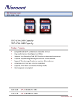
FIGURE 1-1. Most of the components shipped with the SC-USB.
SC12 cable and ResourceDVD not shown.
2. Technical Specifications
2.1 USB Specifications
• USB Version 1.1
• USB transfer rate up to 12 MBits/second
• Active current consumption less than 85 mA (current drawn from PC)
• Standby current consumption less than 18 mA (current drawn from PC)
• 17648 Cable Description: 6 ft (1.8 m) length; USB Type A male to Type B
male.
2.2 CS I/O Port Specifications
• Opto-isolated from the PC/USB to 47 V AC or DC. Note that this is
signal isolation only, and does not provide safety isolation.
• Supports asynchronous communication from 9600 to 115200 baud and
synchronous communication up to 1 MBit/second.
• Campbell Scientific protocols implemented: supports Modem-Enable
(ME), Synchronous Device Communications protocol (SDC) and
Concurrent-SDC (CSDC) modes. Some of these modes may require that
the datalogger operating system be a specific version or higher. The SDC
mode only works with operating systems created since October 2002
(CR10X 1.18 or higher, CR23X 1.15 or higher, etc.) The CSDC mode
only works with a PakBus (PB) operating system and the CR5000.
• Dataloggers supported 21X, CR7X, CR500, CR510, CR10, CR10X / TD /
PB, CR23X / TD / PB, CR6, CR1000, CR800 series, CR3000 and
CR5000.

SC-USB USB to CS I/O Opto-isolated Interface
3
• PC software compatibility PC200W, PC400, LoggerNet, RTDAQ and most
other packages that support virtual serial ports.
• Active current consumption less than 19 mA (current drawn from
datalogger).
• Quiscent current consumption less than 80 µA (current drawn from
datalogger).
2.3 General Specifications
• Height: 0.8 in (2 cm)
Width: 1.6 in (4 cm)
Length: 3.0 in (7.5 cm)
• Weight: 3.0 oz
• Operating temperature range -25° to +50°C
• EMC compliance: complies with EN61326:1998 (see Section 6.3,
Electronic Interference
(p. 18))
• Driver support for Windows 2000 / Windows XP / Windows Vista /
Windows 7 / Windows 8 / Windows 10 supplied on CD (Contact
Campbell Scientific for other drivers)
2.4 Ships With
• 17648 USB cable for connection to the PC’s USB port.
• SC12 CS I/O cable for connection to the datalogger.
• Driver CD containing setup utility and manual.
• ResourceDVD.
3. Installation
3.1 Driver Installation
The installation procedure is straightforward. Whenever possible you should
install the drivers for the SC-USB on the PC before plugging in the SC-USB
for the first time. The drivers need to be installed from the CD provided with
the product or using the package downloaded from the internet.
If using a CD, the setup program should start to run when the CD is first
inserted into the machine, if allowed by the security settings of the PC. If this
does not happen, browse to the CD and run the autorun.exe program in the root
directory of the CD.

SC-USB USB to CS I/O Opto-isolated Interface
4
When started, the program will present a menu like this:
Select the option to install the 32- or 64-bit drivers depending on your PC
operating system (32-bit is the only valid option for Windows XP and
Windows 2000).
A separate installer program will start if you have selected the appropriate
driver set for your copy of Windows.

SC-USB USB to CS I/O Opto-isolated Interface
5
After clicking Next, the drivers will be installed. The program should
complete with the following screen.
Once this step has been reached, click on Finish and you can proceed to
connect the SC-USB to your computer.
3.2 Installing the SC-USB for the First Time
Connect the SC-USB to a USB port on your PC. If the drivers have been
installed on the machine using the process above, the PC should find the
correct drivers. After going through two cycles of finding and installing
drivers, the PC should show the newly found USB device and display a
message that the device is ready to use. If you have upgraded the drivers, you
may be asked to reboot your computer before using the interface.
3.3 Fixing a Failed Installation/Upgrading the Drivers
If you have not installed the drivers prior to plugging in the SC-USB,
depending on the version of Windows that you have, the installation will either
fail with no option to search for the drivers or it will fail and ask for a disk to
be installed. In the latter case, you can insert the SC-USB driver disk in the
computer, browse to the CD, and let Windows install the drivers from the CD.
Newer versions of Windows will not give this option before failing. Therefore,
you will need to perform the following steps. The same steps can be used to
ensure that Windows is using the latest drivers. Please note that the screens
below are from Windows 7. The exact appearance and wording will vary with
other operating systems.
First, use the CD to install the latest drivers onto the PC as described in Section
3.1, Driver Installation
(p. 3). Next, with the SC-USB plugged into the PC, open
up the Device Manager screen of Windows. This can be done either by

SC-USB USB to CS I/O Opto-isolated Interface
6
browsing to the Device Manager via the Control Panel or by using the search
tool and running devmgmt.msc.
If the install failed, in the Device Manager you will see SC-USB USB TO CS
I/O INTERFACE listed under Other Devices with a yellow warning symbol
to indicate a problem, as there is no driver installed yet. If you are attempting
to upgrade the driver, the yellow symbol may not be present.
Right click on SC-USB USB TO CS I/O INTERFACE and click on Update
Driver Software in the menu that appears.

SC-USB USB to CS I/O Opto-isolated Interface
7
You will then be prompted as to whether to search for the driver or browse the
computer.
If the driver installation as shown in Section 3.1, Driver Installation
(p. 3), was
successful, you can select the first option and the new drivers already installed
on the machine should be found. If not, browse to the CD and see if Windows
will find the drivers from there. If the drivers are found, you should see a
screen like this:

SC-USB USB to CS I/O Opto-isolated Interface
8
Once this part of the installation is complete, you will see the following
confirmation:
Click Close to return to the Device Manager.
You will now see SC-USB USB TO CS I/O ISOLATED INTERFACE
displayed under Universal Serial Bus controllers as shown below:

SC-USB USB to CS I/O Opto-isolated Interface
9
You will now notice a new device USB Serial Port displayed under Ports
(COM & LPT), again with a yellow warning symbol as a driver is not
installed yet.
Right click on USB Serial Port and click Update Driver Software in the
menu that appears:
You will now be given the choice to search automatically or browse for driver
software. If previously installed successfully, click on Search. If it was not
successful, browse to the CD to point to the drivers.

SC-USB USB to CS I/O Opto-isolated Interface
10
The installation will then proceed and you will see the progress as follows:
Once this part of the installation is complete, you will see the following
confirmation:
Click Close to return to the Device Manager.

SC-USB USB to CS I/O Opto-isolated Interface
11
You will now see SC-USB USB TO CS I/O ISOLATED INTERFACE
(COMx) displayed under Ports (COM & LPT), where x is the number of the
COM port assigned by Windows during the installation.
The installation is now complete. You can close the Device Manager and start
using your SC-USB interface.
3.4 Uninstalling the SC-USB Drivers
To remove the drivers, start the Device Manager (see Section 3.3, Fixing a
Failed Installation/Upgrading the Drivers
(p. 5)). With the SC-USB plugged in,
you will see it listed under Ports. Right-click on its entry and select the
Uninstall option. Select the option to delete the files if required. You can then
unplug the SC-USB. Plugging the SC-USB back in later should restart the
installation process.
3.5 Determining Which COM Port the SC-USB Has Been
Assigned
The above installation processes relies on parts of the Windows operating
system to assign a COM port number to the SC-USB. Often this will be the
next port number that is free. However, if other devices have been installed in
the past (some of which may no longer be plugged in), it may be assigned a
higher COM port number.
To check which COM port it has been assigned, you can simply monitor the
appearance of a new COM port in the list of COM ports offered in your
software package (for example, LoggerNet) before and after the installation. If
there is any question, look in the Windows Device Manager list under the
Ports section (accessed via the Control Panel).

SC-USB USB to CS I/O Opto-isolated Interface
12
As shown below, the COM port number is shown at the end of the description:
In some cases, a PC program may not offer the SC-USB COM port in its
selection list of available COM ports. Recent versions of Campbell Scientific
packages allow you to manually type the COM port into the selection window
to overcome this.
Older software may also limit you up to COM4. In that case, you would need
to free lower COM port numbers (by uninstalling an unused COM port) and
move the assignment of the SC-USB. To do this, right click on the SC-USB in
the Device Manager screen (as shown above) and select Properties. Select
Port Settings and then the Advanced button. In the next screen you have the
option to change the COM port number to another free number. OK any
change you make and close the Device Manager screen before reopening it to
confirm the change (it does not automatically refresh this change).
The baud rate settings in the driver/properties setting have no
influence on the operation of the SC-USB. The speed of
communication to the datalogger is normally determined
automatically by the SC-USB although it can be set in other ways.
See the sections below.
NOTE
/