Page is loading ...

Halsey Taylor Owners Manual
Models: HT-SBP-FR HT-EBP-FR HT-SEBP-FR
Freeze Resistant Fountains
Installer
To assure you install this model easily and correctly, PLEASE READ THESE SIMPLE INSTRUC-
TIONS BEFORE STARTING THE INSTALLATION. CHECK YOUR INSTALLATION FOR COMPLI-
ANCE WITH PLUMBING, ELECTRICAL AND OTHER APPLICABLE CODES. After installation,
leave these instructions inside the fountain for future reference. This Freeze Resistant Fountain is
shipped in two separate cartons. The second carton contains the Freeze Resistant Package that
is installed on an interior heated wall. Refer to the Freeze Resistant Package for the rough-in
dimensions for installation.
IMPORTANT! INSTALLER PLEASE NOTE.
THE GROUNDING OF ELECTRICAL EQUIPMENT SUCH AS TELEPHONE, COMPUTERS, ETC. TO WATER LINES IS
A COMMON PROCEDURE. THIS GROUNDING MAY BE IN THE BUILDING OR MAY OCCUR AWAY FROM THE
BUILDING. THIS GROUNDING CAN CAUSE ELECTRICAL FEEDBACK INTO A FOUNTAIN, CREATING AN ELEC-
TROLYSIS WHICH CAUSES A METALLIC TASTE OR AN INCREASE IN THE METAL CONTENT OF THE WATER. THIS
CONDITION IS AVOIDABLE BY USING THE PROPER MATERIALS AS INDICATED. ANY DRAIN FITTINGS PROVIDED
BY THE INSTALLER SHOULD BE MADE OF PLASTIC TO ELECTRICALLY ISOLATE THE FOUNTAIN FROM THE
BUILDING PLUMBING SYSTEM.
IMPORTANT
ALL SERVICE TO BE PERFORMED BY AN AUTHORIZED SERVICE PERSON
PAGE 1
HT-SBP-FR, HT-EBP-FR, HT-SEBP-FR
97642C (Rev. C - 11/01)
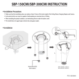
FIG. 1
TUBE IS
SECURED
IN POSITION
SIMPLY PUSH IN
TUBE TO ATTACH
PUSH IN COLLET
TO RELEASE TUBE
PUSHING TUBE IN BEFORE
PULLING IT OUT HELPS TO
RELEASE TUBE
FIG. 2
OPERATION OF QUICK CONNECT FITTINGS
NOTE: WATER FLOW
DIRECTION
BUILDING WATER INLET
SERVICE STOP
(NOT FURNISHED)
1/4" O.D. TUBE
WATER INLET
TO COOLER
3/8" O.D. UNPLATED
COPPER TUBE CONNECT
COLD WATER SUPPLY

PAGE 297642C (Rev. C - 11/01)
HT-SBP-FR, HT-EBP-FR, HT-SEBP-FR
1. Wall should already be framed for the fountain using dimensions shown in Fig. 3. Shown dimensions pertain to installation location.
These dimensions are required for compliance with ANSI Standard A117.1. (and ADA) (Framing shown for reference only).
2. Remove bottom cover from fountain and save the screws. Assemble push rod to fountain. (Push rod provided with frost-resistant box)
3. Install the fountain using bolts and washers (provided). Tighten securely.
4. Attach drain tube to fountain and cut to required length using the frost resistant box as a guide.
5. Install frost-resistant box - see box instructions.
6. Install a service stop (not provided) and make water supply connection from the stop to the strainer in the frost-resistant box.
7. Connect fountain water line to frost-resistant box - see box instructions. Replace bottom cover.
FIG. 3
FINISHED FLOOR
LEGEND
A = 1 3/4" DIA. (44mm) HOLE FOR WASTE LINE
B = 7/8" DIA. (22mm) HOLE FOR WATER INLET
C = 1/4" DIA. (6mm) HOLES FOR MOUNTING PLATE TO WALL
HT - EBP - FR ROUGH-IN

PAGE 3 97642C (Rev. C - 11/01)
HT-SBP-FR, HT-EBP-FR, HT-SEBP-FR
FIG. 4
FINISHED FLOOR
HT - EBP - FR ROUGH-IN

PAGE 497642C (Rev. C - 11/01)
HT-SBP-FR, HT-EBP-FR, HT-SEBP-FR
1. Wall should already be framed for the fountain using dimensions shown in Fig. 5. Shown dimensions pertain to installation location.
These dimensions are required for compliance with ANSI Standard A117.1. (and ADA) (Framing shown for reference only).
2. Remove bottom cover from fountain and save the screws. Assemble push rod to fountain. (Push rod provided with frost-resistant box)
3. Install the fountain using bolts and washers (provided). Tighten securely.
4. Attach drain tube to fountain and cut to required length using the frost resistant box as a guide.
5. Install frost-resistant box - see box instructions.
6. Install a service stop (not provided) and make water supply connection from the stop to the strainer in the frost-resistant box.
7. Connect fountain water line to frost-resistant box - see box instructions. Replace bottom cover.
LEGEND
A = 1 3/4" DIA. (44mm) HOLE FOR WASTE LINE
B = 7/8" DIA. (22mm) HOLE FOR WATER INLET
C = 1/4" DIA. (6mm) HOLES FOR MOUNTING PLATE TO WALL
HT - SBP - FR ROUGH-IN
FINISHED FLOOR
FIG. 5

PAGE 5 97642C (Rev. C - 11/01)
HT-SBP-FR, HT-EBP-FR, HT-SEBP-FR
FIG. 6
FINISHED FLOOR

PAGE 697642C (Rev. C - 11/01)
HT-SBP-FR, HT-EBP-FR, HT-SEBP-FR
1. Wall should already be framed for the fountains using dimensions shown in Fig. 7. Shown dimensions pertain to installation location.
These dimensions are required for compliance with ANSI Standard A117.1. (and ADA) (Framing shown for reference only).
2. Remove bottom covers from fountains and save the screws. Assemble push rods to fountains. (Push rods provided with frost-resistant boxes)
3. Install the fountains using bolts and washers (provided). Tighten securely.
4. Attach drain tubes to fountains and cut to required length using the frost resistant boxes as guides.
5. Install frost-resistant boxes - see box instructions.
6. Install a service stops (not provided) and make water supply connections from the stops to the strainers in the frost-resistant boxes.
7. Connect fountain water lines to frost-resistant boxes - see box instructions. Replace bottom covers.
FIG. 7
LEGEND
A = 1-3/4" DIA. (44mm) HOLE FOR
WASTE LINE
B = 7/8" DIA. (22mm) HOLE FOR
WATER INLET
C = 1/4" (6mm) HOLE FOR
MOUNTING PLATE TO WALL
HT - SEBP - FR ROUGH-IN
FINISHED FLOOR

PAGE 7 97642C (Rev. C - 11/01)
HT-SBP-FR, HT-EBP-FR, HT-SEBP-FR
FINISHED FLOOR
FIG. 8
HT - SEBP - FR ROUGH-IN

PAGE 897642C (Rev. C - 11/01)
HT-SBP-FR, HT-EBP-FR, HT-SEBP-FR
DESCRIPTION
51546C
100322740560
66354C
66355C
160270508640
161637308650
100147140560
66346C
66343C
22913C
22915C
23001C
23002C
55864C
*55000458
*50003C
*70054C
55884C
75588C
110711942550
75589C
28016C
23187C
28017C
28172C
28158C
28174C
75541C
111577243890
1
2
3
4
5
6
7
8
9
10
11
12
13
14
15
16
17
NS
NS
NS
NS
NS
NS
NS
NS
PART NO.
Bubbler
Gasket - Bubbler
Tube Assy - Bubbler (Long Ftn)
Tube Assy - Bubbler (Short Ftn)
Strainer Plate
Drain Plug
Gasket-Drain
Tube - Waste (Long Ftn)
Tube - Waste (Short Ftn)
Basin (Long Ftn)
Basin (Short Ftn)
Cover - Bottom (Long Ftn)
Cover - Bottom (Short Ftn)
Bushing - Snap 1/2" I.D.
Push Button Assy
Bushing - Snap
Nut - Speed
Elbow-Drain
Nut-Slip Joint
Screw - #8-32 x 3/8 TH
Gasket
Panel - Single
Panel - Single
Panel - Double
Wall Plate Assembly - HT-EBP
Wall Plate Assembly - HT-SBP
Wall Plate Assembly - HT-SEBP
Washer-Flat .339/.359ID Steel
Screw-Mach. 5/16-18 x 3/4
ITEM NO.
PARTS LIST
* PARTS SUPPLIED WITH FREEZE-RESISTANT BOX
FOR PARTS, CONTACT YOUR LOCAL DISTRIBUTOR OR CALL 1.800.323.0620
2222 CAMDEN COURT
OAK BROOK, IL 60521
630.574.3500
PRINTED IN U.S.A.
STREAM HEIGHT ADJUSTMENT:
Stream height is factory set at 35 PSI. If supply
pressure varies greatly from this, adjust screw on
regulator in freeze resistant box. Clockwise adjustment
will raise stream and counter-clockwise adjustment will
lower stream. For best adjustment, stream should hit
basin approximately 6-1/2" from the bubbler.
Fig. 9
1
3
4, 5, 6
8
2
7
12
13
14
15, 17
9
11
10
FIG. 10
16
/