Page is loading ...

Application Report
SCBA031–August 2012
TMS3705 Range Extender Power Solution Using
UCC27424-Q1
Siegfried Langner.............................................................................................................................
ABSTRACT
This application report provides supplementary information about the Texas Instruments 134.2 kHz RFID
Base Station IC TMS3705x in combination with an external driver IC. In particular, the document shows a
low cost and easy-to-implement solution to improve the communication distance between the transaction
processor (TRP) and the Reader unit.
Contents
1 Introduction .................................................................................................................. 1
2 Main Features ............................................................................................................... 2
3 System Options ............................................................................................................. 5
4 References ................................................................................................................. 16
List of Figures
1 Standard HDX RFID Reader Configuration ............................................................................. 2
2 TMS3705x With External Amplifier ...................................................................................... 3
3 Circuit Block Diagram of External Amplifier UCC27424 .............................................................. 4
4 Typical LF-UHF Hands-Free System..................................................................................... 5
5 Conventional “Long” Antenna Cable Solution .......................................................................... 6
6 Extended Power Configuration with “Long” Antenna Cable........................................................... 6
7 Schematic Connection of the Driver IC (UCC27424) .................................................................. 7
8 Pulse Width Downlink Telegram .......................................................................................... 8
9 Detailed Downlink Telegram With TMS3705 Modulation (TXCT) .................................................... 8
10 Schematic Connection of the Driver IC (UCC27424) .................................................................. 9
11 Down-Link Telegram With UCC Modulation ............................................................................ 9
12 Multiplexer Solution Using Multiple UCC27424 Devices ............................................................ 10
13 Timing Diagram MUX 2-Channel........................................................................................ 11
14 Application Schematic With TMS3705 Modulation.................................................................... 12
15 Complete Transponder Communication................................................................................ 13
16 Block Schematic of CRC Generator .................................................................................... 14
List of Tables
1 Introduction
The Texas Instruments low-frequency transponder Base-Station IC supports all TI low-frequency
transponders types. For certain applications, a higher filed strength is required in order to extend the
communications distance or increase the charge current in applications where a wireless battery charge is
used. With the combination of the two TI devices, an easy implementation is possible.
All trademarks are the property of their respective owners.
1
SCBA031–August 2012 TMS3705 Range Extender Power Solution Using UCC27424-Q1
Submit Documentation Feedback
Copyright © 2012, Texas Instruments Incorporated

L1
R3
4R7
R4
4R7
C2
C3
Cres.
R1
47k
R2
150k
To Band Pass
and Limiter
Diagnosis
Vref
5
7
6
Ant2
Ant1
GND
1
2
SFB
SENSE
TMS3705
Full
Bridge
Antenna
Driver
Main Features
www.ti.com
In addition, faster down-link modulation can be realized by using the TMS3705x as an oscillator only and
performing the modulation with the enable input of the UCC27424. In this way a minimum transmitter on-
off time is possible (15 µs @ 134.2 kHz).
The UCC27423, UCC27424 and UCC27425 high-speed dual MOS field effect transistor (MOSFET)
drivers can deliver a large peak current into capacitive loads. For the specific application, the dual non-
inverting type is used.
2 Main Features
• Drive of higher antenna current
• Increase of communication distance
• Use of low-inductance antennas because of higher driver current capability
• Few additional components necessary
• Reference designs are available
• Realization of rechargeable applications (for example, PaLFI)
• Use for active hands-free access systems (motor bikes, machine access)
2.1 Conventional System
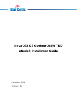
The circuitry in Figure 1 shows the standard TMS3705x schematic if “no” antenna cable is used. For more
information, see the TMS3705 Transponder Base Station IC Datasheet (SCBS881).
Figure 1. Standard HDX RFID Reader Configuration
2
TMS3705 Range Extender Power Solution Using UCC27424-Q1 SCBA031–August 2012
Submit Documentation Feedback
Copyright © 2012, Texas Instruments Incorporated

IN A
IN B
Enabl
e
Out
A
Out
B
L1
R3
4R7
R4
4R7
C2
C3
Cres.NPO**
R1
47k
R2
150k
Diagnosis
Vref
5
7
6
GND
1
2
SFB
SENSE
TMS3705
VDDA
8
IN_A
IN_B
Out
A
Out
B
ENB
ENB
+5V
+12V
** DC withstand voltage> peak Voltage
Vpp = VS*2*Q
VS
To Band Pass
and Limiter
Ant2
Full
Bridge
Antenna
Driver
Ant1
UCC
27424
Full Bridge
Driver
www.ti.com
Main Features
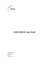
2.2 System Using an External Full Bridge Amplifier
The circuitry in Figure 2 shows the combination of the TMS3705 plus an external amplifier. The outputs of
the TMS3705 are simply connected to the inputs of the amplifier. Since the amplifier is supplied by a
higher supply voltage, a higher antenna current can be driven.
Figure 2. TMS3705x With External Amplifier
3
SCBA031–August 2012 TMS3705 Range Extender Power Solution Using UCC27424-Q1
Submit Documentation Feedback
Copyright © 2012, Texas Instruments Incorporated

1
2
4
3
8
7
6
5
ENBA
BLOCK DIAGRAM
INVERTING
ENBB
INA
GND
INB
NON-INVERTING
INVERTING
NON-INVERTING
OUTA
VDD
VDD
OUTB
UDG-01063
Main Features
www.ti.com
Figure 3. Circuit Block Diagram of External Amplifier UCC27424
2.3 System Considerations
An active identification system is located on the base station side of a low frequency transmitter and a
UHF receiver, while the identification device (Key) has a low frequency receiver (3D Analog Front End) in
combination with a Micro controller and a UHF Transmitter.
2.4 Typical Base Station for a Hands-Free System
Figure 4 shows a typical system for realizing a hands-free system that can be used for access of
machines, for example, motor bikes. Also a wireless anti-theft system can be realized in combination with
an active key fob.
Depending on the transmit antenna parameters, as well as the fob antenna parameters, a wake up
distance up to two meters can be reached.
4
TMS3705 Range Extender Power Solution Using UCC27424-Q1 SCBA031–August 2012
Submit Documentation Feedback
Copyright © 2012, Texas Instruments Incorporated

TMS3705x
TRP Base Station IC
134.2kHz
µ
Controller
UCC27424
Full Bridge Antenna Driver
ANT1
Loop
Antenna
Air Coil or Ferrite
inductance
100 to 500µH
UHF
Receiver
V-Reg
5Volt
V-Reg
10Volt
TXCT
Data
TRP Receive Path
Vcc
Vbat
5Volt
Enable
Trigger
GPO
Lz
Lx
Ly
RF2
RF1
RF3
VCl
CL
TMS37F128D3
AFE+TRP+MSP430
A
F
E
µC
Passive
Transponder
3D Active Key-Fob
UHF
Transmitter
GPO
ANT2
supplyed by a higher
Voltage
www.ti.com
System Options
Figure 4. Typical LF-UHF Hands-Free System
3 System Options
3.1 Remote Antenna System – “Long” Antenna Cable
The extended power solution can also be combined with the long antenna cable system as shown in
Figure 6.
The generic circuitry for the “long” cable application shows the additional recommended components that
are needed.
5
SCBA031–August 2012 TMS3705 Range Extender Power Solution Using UCC27424-Q1
Submit Documentation Feedback
Copyright © 2012, Texas Instruments Incorporated

IN A
IN B
EnableOut
A
Out
B
Full
Bridge
Antenna
Driver
R3
4R7
R4
4R7
C2
C3
Cres. NPO**
R1
47k
R2
150k
To Band Pass
and Limiter
Diagnosis
Vref
5
7
6
Ant2
Ant1
GND
1
2
SFB
SENSE
TMS3705
VDDA
8
C4
100n
R5
1K
(10K)
UCC
27424
Full Bridge
Driver
IN_A
IN_B
Enable
Out
A
Out
B
ENB
ENB
+5V
+12V
** withstand voltage
VS*Q
VS
> 80Vpp
134kHz
L1
Long Antenna
cable
L1
Full
Bridge
Antenna
Driver
R3
4R7
R4
4R7
C2
C3
Cres.
R1
47k
R2
150k
To Band Pass
and Limiter
Diagnosis
Vref
5
7
6
Ant2
Ant1
GND
1
2
SFB
SENSE
TMS3705
C4
100n
R5
1K
(10K)
Long Antenna cable
System Options
www.ti.com
Figure 5. Conventional “Long” Antenna Cable Solution
Figure 6. Extended Power Configuration with “Long” Antenna Cable
6
TMS3705 Range Extender Power Solution Using UCC27424-Q1 SCBA031–August 2012
Submit Documentation Feedback
Copyright © 2012, Texas Instruments Incorporated

L1
Full
Bridge
Antenna
Driver
R3
4R7
R4
4R7
C2
C3
Cres.NPO**
R1
47k
R2
150k
To Band Pass
and Limiter
Diagnosis
Vref
5
7
6
Ant2
Ant1
GND
1
2
SFB
SENSE
TMS3705
VDDA
8
UCC
27424
Full Bridge
Driver
IN_A
IN_B
Out
A
Out
B
sldkfjoösajdf
ENB
ENB
+5V
+12V
** DC withstand voltage> peak Voltage
Vpp = VS*2*Q
VS
TXCT
10k
TX-ON
Low-Level
Modulation
www.ti.com
System Options
3.2 Transmitter Modulation
The following block describes the different possibilities to modulate the low frequency field.
3.2.1 Normal Modulation Using the 3705 TXCT Input
The data transmission in the direction of the transponder (downlink) is done with 100% AM modulation.
The coding is transponder specific and requires transponder-specific timing. Data coding is, for example,
pulse width modulation (PWM) or pulse position modulation (PPM).
The specific downlink coding is defined in the transponder specification. In general, it is always a particular
transmitter ON-OFF sequence.
For the TMS3705x, the minimum transmitter ON and OFF time is 100 µs. This is determined by the t
dwrite
signal delay for controlling the full bridge antenna driver.
For more information, see the SWITCHING CHARACTERISTICS section in the TMS3705 Transponder
Base Station IC Data Sheet (SCBS881).
Figure 7. Schematic Connection of the Driver IC (UCC27424)
Typical Pulse-Width downlink telegram (Read page3, 0x0C).
Timing:
High Bit: Low Bit:
170 µs off 480 µs off
330 µs on 520 µs on
7
SCBA031–August 2012 TMS3705 Range Extender Power Solution Using UCC27424-Q1
Submit Documentation Feedback
Copyright © 2012, Texas Instruments Incorporated

System Options
www.ti.com
Figure 8. Pulse Width Downlink Telegram
3.2.2 Transmitter ON-OFF Delay of the TMS3705x
The screen shots in Figure 9 show the ON propagation delay of the TXCT signal that limits the downlink
timing. This does not impact a normal TRP operation.
Figure 9. Detailed Downlink Telegram With TMS3705 Modulation (TXCT)
3.2.3 Modulation Using the Enable Input of the UCC27424 for High Baud Rate
In case a higher downlink baud rate is required, the TMS3705x can be used as an oscillator only while
modulation is performed by the enable pins of the UCC27424. This allows a transmitter on time of as little
as two RF cycles (15 µs at 134 kHz). Of course the time until the maximum resonance voltage is reached
depends on the resonance Q-factor, since the higher the Q, the longer it takes to reach maximum
amplitude.
8
TMS3705 Range Extender Power Solution Using UCC27424-Q1 SCBA031–August 2012
Submit Documentation Feedback
Copyright © 2012, Texas Instruments Incorporated

L1
Full
Bridge
Antenna
Driver
R3
4R7
R4
4R7
C2
C3
Cres.NPO**
R1
47k
R2
150k
To Band Pass
and Limiter
Diagnosis
Vref
5
7
6
Ant2
Ant1
GND
1
2
SFB
SENSE
TMS3705
VDDA
8
UCC
27424
Full Bridge
Driver
IN_A
IN_B
Out
A
Out
B
sldkfjoösajdf
ENB
ENB
+5V
+12V
** DC withstand voltage> peak Voltage
Vpp = VS*2*Q
VS
TXCT
10k
TX-ON
Low-Level
Modulation
www.ti.com
System Options
Figure 10. Schematic Connection of the Driver IC (UCC27424)
Figure 11. Down-Link Telegram With UCC Modulation
NOTE: Since the enable pin logic is active high, the modulation signal must be inverted in respect to
the TXCT modulation signal of the 3705. The UCC enable pins must be activated for the 20
ms receive time after the TXCT was set to high.
3.3 Multiplexer Solution Using Multiple UCC27424 Devices
Figure 12 shows an easy to realize multiplexer solution using one TMS3705x and multiple boost
amplifiers. By using the individual enable inputs, the different channels can be selected. The selected
channel is not affected by the de-selected channels and visa-versa.
9
SCBA031–August 2012 TMS3705 Range Extender Power Solution Using UCC27424-Q1
Submit Documentation Feedback
Copyright © 2012, Texas Instruments Incorporated

IN A
IN B
Enabl
e
Out
A
Out
B
L1
Full
Bridge
Antenna
Driver
R3
4R7
R4
4R7
C2
C3
Cres.NPO**
R1
47k
R2
150k
To Band Pass
and Limiter
Diagnosis
Vref
5
7
6
Ant2
Ant1
GND
1
2
SFB
SENSE
TMS3705
VDDA
8
UCC
27424
Full Bridge
Driver
IN_A
IN_B
Out
A
Out
B
ENB
ENB
+5V
+12V
VS
RX_1
TXCT
10k
Modulation
TX-ON-Low
L1
R31
4R7
R41
4R7
C21
C31
Cres.NPO**
UCC
27424
Full Bridge
Driver
IN_A
IN_B
Out
A
Out
B
ENB
ENB
+12V
** DC withstand voltage> peak Voltage
Vpp = VS*2*Q
VS
RX_2
µC
Enable/Modulation Channel_1
Enable/Modulation Channel_2
R11
47k
RX_2
RX_2
RX_2
System Options
www.ti.com
Figure 12. Multiplexer Solution Using Multiple UCC27424 Devices
NOTE: Since Out A and Out B of the non-enabled driver are set to a low level, the antenna Lx and
the resonance capacitor Cres are switched in parallel resonance; noise at the RX-path can
influence the read performance of the selected channel.
3.4 Timing Diagram Sequence - Read Two Channels (Modulation With TXCT)
Figure 13 shows the sequence of using two amplifiers for a second reading point while only one TMS3705
device is used. The selection of the specific channel is done by the enable input of the amplifier.
10
TMS3705 Range Extender Power Solution Using UCC27424-Q1 SCBA031–August 2012
Submit Documentation Feedback
Copyright © 2012, Texas Instruments Incorporated

TXCT
OSC-
ON
RF
3705
>=20ms
UCC_1
Enable
UCC on for
RX-Time 20ms
Charge phase
TXCT
low
RF_Ch_
1
UCC_2
Enable
CH_1_OFF
RX >=20ms
RF_Ch_
2
CH_2 ON
Receive
Data CH_2
SCIO
3705
Data
Receive
Data CH_2
DIAG
DIAG
www.ti.com
System Options
Figure 13. Timing Diagram MUX 2-Channel
3.5 CAUTION
For exact timing, see the device-specific TRP specification as well as the TMS3705 Transponder Base
Station IC Data Sheet (SCBS0881).
3.6 ESD
It is recommended to protect all pins of the device with additional ESD diodes for higher ESD immunity.
The device itself withstands ESD strikes only up to ± 2kV (MIL STD 883).
In case of a long cable system, do not connect the ESD diode at the resonance pin. It should be
connected as shown in Figure 14
3.7 Resonance Capacitor
The resonance capacitor has to withstand the peak RF voltage if the power stage is supplied with a
voltage higher than 5 V.
The peak-peak voltage is calculated as follows:
V
PP
= VUCC * 2 * Q
The multiplication by two is used because of the full bridge operation. The full bridge amplifier doubles the
voltage compared to a single-ended push-pull stage.
11
SCBA031–August 2012 TMS3705 Range Extender Power Solution Using UCC27424-Q1
Submit Documentation Feedback
Copyright © 2012, Texas Instruments Incorporated

+VA
OUTB
C4, C6 is only needed if internal
load capacitance is not correct
test connector for
connecting external CTL
5
6
7
8
VDD
OUTA
ENBB
INB
GND
INA
ENBA
4
3
2
1
IC2
UCC27424D
4
1
2
3
5
6
7
8
16
15
14
13
12
11
10
9
IC1
TMS3705
SENSE
TXCT_
SFB
D_TST
A_TST
ANT1
VSSA
ANT2
VDDA
F_SEL
SCIO
VSSB
VSS
OSC1
OSC2
VDD
TP6
R7
10k
JP1
1
2
3
GND
R5
FSEL High for 4MHz
R6
1k
TP1
R8
220R
1k
TXCT_
DATA
optional/NPO
GND
C4
Q2
2
GND
GND
1
GND
C6
optional/NPO
CSTCR4M00G55B MURATA
C12
1nF
C11
100nF/X7R
22µF/50V Low ESR
C9
+
C10
100nF/X7R
GND
GND
GND
GNDGND
C7
C8
100nF/X7R
+
22µF/50V Low ESR
TP4
TP2
GND
R2
150k 2%
220pF/NPO/COG)
C2
GND
R3
4R7/100mA
R4
4R7/100mA
D1
C3
220pF/NPO/COG)
GNDGNDGND
D2
3.3nF/NPO/2%/100V
C1
C5
100nF/X7R
10k
R10
JP1_S
JP12
1
2
Value TBD
Antenne 2pin connector
R9
R1
47k 2%
High Voltage during TX
TP3
C1 NPO (High Q), Value depending on Inductance
C2, C3 must be optimized during EMC tests
Footprint for 10nF/NPO shall be planned
C5 is for DC DC decoupling of Antenna pin (short to Vbat)
R9 for providing DC path to GND (Receiver)
D1, D2 Low capacitance bidirectional ESD protection diodes in SOD323
NXP:PESD12VL1BA (12Volt) up to 25kV
R10 damping for reduction of Q Value, TBD
R3, R4 must NOT be a MINIMELF
L antenna Inductance, pay attention to cable capacitance
System Options
www.ti.com
3.8 Application Schematic With TMS3705 Modulation
Figure 14 is the version using the TXCT of the TMS3705 for the 100% AM modulation. The enable signals
(ENBA,ENBB) of the amplifier(IC2) is set to high permanently.
Figure 14. Application Schematic With TMS3705 Modulation
NOTE: You have to consider the antenna cable capacitance if the long cable system is used, which
will have an impact on resonance. The cable capacitance is cable specific.
For more information, see TMS3705 Passive Antenna Solution (SCBA027).
12
TMS3705 Range Extender Power Solution Using UCC27424-Q1 SCBA031–August 2012
Submit Documentation Feedback
Copyright © 2012, Texas Instruments Incorporated

www.ti.com
System Options
3.9 Fast Prototyping and Important Information
Figure 15 shows the communication between the TRP and the Reader. The diagram is applicable for the
MUSA transponder General Read page 3.
Figure 15. Complete Transponder Communication
For a charge-only transponder, the 8-bit command is not necessary. After the charge phase of 50 ms, the
read-only (R/O) TRP sends back its telegram. The telegram length of the R/O and MUSA transponders
are different.
3.9.1 Start Value Cyclic Redundancy Check (CRC)
Please notice that the start values of the CRC are different.
• MUSA: 0x3791
• DST: 0x3791 (all DST-based products)
• R/O: 0x0000
• R/W: 0x0000
13
SCBA031–August 2012 TMS3705 Range Extender Power Solution Using UCC27424-Q1
Submit Documentation Feedback
Copyright © 2012, Texas Instruments Incorporated

+
+
+
LSBMSB
15
(RXDT or TXDT)
SHIFT CLOCK
(RXCK or TXCK)
LOAD
COMPARATOR
DATA
DATA IN
OUT
CRC_OK
'0000000000000000'
SHIFT
SEQGEN2.DRW
START VALUE
14
13
1211
10 9 8 7 6
5
4
3
2 1
0
System Options
www.ti.com
3.9.2 Block Schematic of CRC Generator
A cyclic redundancy check (CRC) generator is used in the transponder during receipt and transmission of
data to generate a 16-bit block check character. For more details, see the device-specific transponder
specification. For M (BCC), applying the CRC-CCITT algorithm (see Figure 9).
Figure 16. Block Schematic of CRC Generator
3.9.3 Telegram Length
The total transponder telegram length (without the 16 pre-bits) is 80 bits starting with the start-byte and
ending with the 16-bit block check character (BCC). The 16 bit pre-bit phase sent by the transponder must
not be included in the CRC. The pre-bits are only used internally by the TMS3705.
3.9.4 Data Direction
Attention should be paid to the data direction. From the transponder side, all data are handled with LS-bit
and LS-byte first.
The serial communications interface (SCI) encoder uses an 8-bit shift register to send the received data
byte-wise (least significant bit (LSB) first) to the microcontroller with a transmission rate of 15.625 kbaud:
one start bit (high) and one stop bit (low). A high level on the SCIO pin indicates the start of transmission
of the data byte. The data bits at the SCIO output are inverted with respect to the corresponding bits sent
by the transponder.
14
TMS3705 Range Extender Power Solution Using UCC27424-Q1 SCBA031–August 2012
Submit Documentation Feedback
Copyright © 2012, Texas Instruments Incorporated

www.ti.com
System Options
3.9.5 Simple C-Code for Receiving Transponder Data at the SCIO
#define SCIO (P2IN & 0x02) //SCI input Port2.1
// variables
unsigned char RX_buff[10]; //
unsigned char trp_data[11]; //
unsigned int BCC_rx; //
unsigned char bit_count_8; //
unsigned char byte_count; //
void RX_80bit(void)
{
unsigned int count; // variable for counter used at
SCIO
count = 1500; // 3.2ms Time out counter value
for first Byte Startbyte 3ms
for (byte_count = 0; byte_count <=0x0A; byte_count+=1) // Loop Byte counter # of Rx bytes.
{
unsigned char temp;
temp = 0;
while ((!SCIO) & (count--!=0)); // wait for SCIO High
{
count = 660; // 520us Time out counter value
interbyte (between 2 bytes)
Delay_us(83); // 64 +32 us start bit + 0.5 bit
1st bit
for (bit_count_8 =0; bit_count_8 <=7; bit_count_8 +=1) // Loop bit read asynch mode
(15625 baud 64us)
{
temp = SCIO; // RX_bit to temp register Px.1
temp <<=6; // temp bit shifted 6-
times(x) to left because P6.1(c)
// starting with MSB x000 000c0
trp_data[byte_count] >>=1; // shift RX-bit by 1 to right
trp_data[byte_count] += temp; // add RX-bit to byte
Delay_us(54); // delay for next bit next bit |-
64us-|-64us-|-64us-|..
}
}
trp_data[byte_count] =~trp_data[byte_count]; // inverts 3705 data to TRP real
TRP format
BCC_rx = trp_data[9];
BCC_rx =( BCC_rx << 8) + trp_data[8]; // BCC_RX xxxx yyyy; TRP
data[8]&[9]
}
Delay_us(1); // for break point
15
SCBA031–August 2012 TMS3705 Range Extender Power Solution Using UCC27424-Q1
Submit Documentation Feedback
Copyright © 2012, Texas Instruments Incorporated

References
www.ti.com
3.9.6 Variable Assignment MUSA/DST
void Clear_buffer(void) //RX Data format MUSA & DST Read Page_3
{
trp_data[0] = 0x00; // Start Byte
trp_data[1] = 0x00; // selective address
trp_data[2] = 0x00; // usr data 1
trp_data[3] = 0x00; // mfg Code
trp_data[4] = 0x00; // ser#1
trp_data[5] = 0x00; // ser#2
trp_data[6] = 0x00; // ser#3
trp_data[7] = 0x00; // read address
trp_data[8] = 0x00; // BCC DST/MUSA
trp_data[9] = 0x00; // BCC DST/MUSA
trp_data[10] = 0x00; // empty
}
NOTE: The C-code is only a sample used for demonstration purpose.
4 References
• TMS3705 Transponder Base Station IC Datasheet (SCBS881)
• TMS3705 Passive Antenna Solution (SCBA027)
16
TMS3705 Range Extender Power Solution Using UCC27424-Q1 SCBA031–August 2012
Submit Documentation Feedback
Copyright © 2012, Texas Instruments Incorporated

IMPORTANT NOTICE
Texas Instruments Incorporated and its subsidiaries (TI) reserve the right to make corrections, enhancements, improvements and other
changes to its semiconductor products and services per JESD46C and to discontinue any product or service per JESD48B. Buyers should
obtain the latest relevant information before placing orders and should verify that such information is current and complete. All
semiconductor products (also referred to herein as “components”) are sold subject to TI’s terms and conditions of sale supplied at the time
of order acknowledgment.
TI warrants performance of its components to the specifications applicable at the time of sale, in accordance with the warranty in TI’s terms
and conditions of sale of semiconductor products. Testing and other quality control techniques are used to the extent TI deems necessary
to support this warranty. Except where mandated by applicable law, testing of all parameters of each component is not necessarily
performed.
TI assumes no liability for applications assistance or the design of Buyers’ products. Buyers are responsible for their products and
applications using TI components. To minimize the risks associated with Buyers’ products and applications, Buyers should provide
adequate design and operating safeguards.
TI does not warrant or represent that any license, either express or implied, is granted under any patent right, copyright, mask work right, or
other intellectual property right relating to any combination, machine, or process in which TI components or services are used. Information
published by TI regarding third-party products or services does not constitute a license to use such products or services or a warranty or
endorsement thereof. Use of such information may require a license from a third party under the patents or other intellectual property of the
third party, or a license from TI under the patents or other intellectual property of TI.
Reproduction of significant portions of TI information in TI data books or data sheets is permissible only if reproduction is without alteration
and is accompanied by all associated warranties, conditions, limitations, and notices. TI is not responsible or liable for such altered
documentation. Information of third parties may be subject to additional restrictions.
Resale of TI components or services with statements different from or beyond the parameters stated by TI for that component or service
voids all express and any implied warranties for the associated TI component or service and is an unfair and deceptive business practice.
TI is not responsible or liable for any such statements.
Buyer acknowledges and agrees that it is solely responsible for compliance with all legal, regulatory and safety-related requirements
concerning its products, and any use of TI components in its applications, notwithstanding any applications-related information or support
that may be provided by TI. Buyer represents and agrees that it has all the necessary expertise to create and implement safeguards which
anticipate dangerous consequences of failures, monitor failures and their consequences, lessen the likelihood of failures that might cause
harm and take appropriate remedial actions. Buyer will fully indemnify TI and its representatives against any damages arising out of the use
of any TI components in safety-critical applications.
In some cases, TI components may be promoted specifically to facilitate safety-related applications. With such components, TI’s goal is to
help enable customers to design and create their own end-product solutions that meet applicable functional safety standards and
requirements. Nonetheless, such components are subject to these terms.
No TI components are authorized for use in FDA Class III (or similar life-critical medical equipment) unless authorized officers of the parties
have executed a special agreement specifically governing such use.
Only those TI components which TI has specifically designated as military grade or “enhanced plastic” are designed and intended for use in
military/aerospace applications or environments. Buyer acknowledges and agrees that any military or aerospace use of TI components
which have not been so designated is solely at the Buyer's risk, and that Buyer is solely responsible for compliance with all legal and
regulatory requirements in connection with such use.
TI has specifically designated certain components which meet ISO/TS16949 requirements, mainly for automotive use. Components which
have not been so designated are neither designed nor intended for automotive use; and TI will not be responsible for any failure of such
components to meet such requirements.
Products Applications
Audio www.ti.com/audio Automotive and Transportation www.ti.com/automotive
Amplifiers amplifier.ti.com Communications and Telecom www.ti.com/communications
Data Converters dataconverter.ti.com Computers and Peripherals www.ti.com/computers
DLP® Products www.dlp.com Consumer Electronics www.ti.com/consumer-apps
DSP dsp.ti.com Energy and Lighting www.ti.com/energy
Clocks and Timers www.ti.com/clocks Industrial www.ti.com/industrial
Interface interface.ti.com Medical www.ti.com/medical
Logic logic.ti.com Security www.ti.com/security
Power Mgmt power.ti.com Space, Avionics and Defense www.ti.com/space-avionics-defense
Microcontrollers microcontroller.ti.com Video and Imaging www.ti.com/video
RFID www.ti-rfid.com
OMAP Mobile Processors www.ti.com/omap TI E2E Community e2e.ti.com
Wireless Connectivity www.ti.com/wirelessconnectivity
Mailing Address: Texas Instruments, Post Office Box 655303, Dallas, Texas 75265
Copyright © 2012, Texas Instruments Incorporated
/