EuroLite LED FE-700 User manual
- Category
- Stroboscopes & disco lights
- Type
- User manual

BEDIENUNGSANLEITUNG
USER MANUAL
LED FE-700
Flower Effect

00091062.DOC, Version 1.1
2/28
Inhaltsverzeichnis / Table of contents
!"#$%&&&&&&&&&&&&&&&&&&&&&&&&&&&&&&&&&&&&&&&&&&&&&&&&&&&&&&&&&&&&&&&&&&&&&&&&&&&&&&&&&&&&&&&&&&&&&&&&&&&&&&&&&&&&&&&&&&&&&&&&&&&&&&&&&&&&&&&&&&&&&&&&&&&'
("$!$!")($"*!"(!&&&&&&&&&&&&&&&&&&&&&&&&&&&&&&&&&&&&&&&&&&&&&&&&&&&&&&&&&&&&&&&&&&&&&&&&&&&&&&&&&&&&&&&&&&&&&&&&&&&&&&&&&&&&&&&&&&&&&&&&&&&&&&&&&'
+!()",,%(!,-.!/!*!0%&&&&&&&&&&&&&&&&&&&&&&&&&&&&&&&&&&&&&&&&&&&&&&&&&&&&&&&&&&&&&&&&&&&&&&&&&&&&&&&&&&&&&&&&&&&&&&&&&&&&&1
!-)!+!($!"+%&&&&&&&&&&&&&&&&&&&&&&&&&&&&&&&&&&&&&&&&&&&&&&&&&&&&&&&&&&&&&&&&&&&&&&&&&&&&&&&&&&&&&&&&&&&&&&&&&&&&&&&&&&&&&&&&&&&&&&&&&&&&&&&2
Features: ........................................................................................................................................................ 6
Geräteübersicht .............................................................................................................................................. 6
"()3443)"5&&&&&&&&&&&&&&&&&&&&&&&&&&&&&&&&&&&&&&&&&&&&&&&&&&&&&&&&&&&&&&&&&&&&&&&&&&&&&&&&&&&&&&&&&&&&&&&&&&&&&&&&&&&&&&&&&&&&&&&&&&&&&&&&&&&&&&&&&&&&&&&&6
Überkopfmontage ........................................................................................................................................... 7
DMX512-Ansteuerung .................................................................................................................................... 8
Master/Slave-Betrieb ...................................................................................................................................... 9
Anschluss zwischen Geräten ......................................................................................................................... 9
Anschluss ans Netz ...................................................................................................................................... 10
+!0"!%&&&&&&&&&&&&&&&&&&&&&&&&&&&&&&&&&&&&&&&&&&&&&&&&&&&&&&&&&&&&&&&&&&&&&&&&&&&&&&&&&&&&&&&&&&&&&&&&&&&&&&&&&&&&&&&&&&&&&&&&&&&&&&&&&&&&&&&&&&&&&&&&&&&78
Standalone-Modus ....................................................................................................................................... 10
Control Board ............................................................................................................................................... 10
0,9:!()!%!)!+!)"!+&&&&&&&&&&&&&&&&&&&&&&&&&&&&&&&&&&&&&&&&&&&&&&&&&&&&&&&&&&&&&&&&&&&&&&&&&&&&&&&&&&&&&&&&&&&&&&&&&&&&&&&&&&&&&&&&&&&&7;
DMX-Modus ................................................................................................................................................. 12
DMX-Protokoll .............................................................................................................................................. 13
Fernbedienung EUROLITE IR-7 .................................................................................................................. 14
!""%%0*3)%&&&&&&&&&&&&&&&&&&&&&&&&&&&&&&&&&&&&&&&&&&&&&&&&&&&&&&&&&&&&&&&&&&&&&&&&&&&&&&&&&&&&&&&&&&&&&&&&&&&&&&&&&&&&&&&&&&&&&&&&71
Sicherungswechsel ...................................................................................................................................... 16
)!$"($!03)!&&&&&&&&&&&&&&&&&&&&&&&&&&&&&&&&&&&&&&&&&&&&&&&&&&&&&&&&&&&&&&&&&&&&&&&&&&&&&&&&&&&&&&&&&&&&&&&&&&&&&&&&&&&&&&&&&&&&&&&&&&&&&&&&&&&&72
")50%)"5&&&&&&&&&&&&&&&&&&&&&&&&&&&&&&&&&&&&&&&&&&&&&&&&&&&&&&&&&&&&&&&&&&&&&&&&&&&&&&&&&&&&&&&&&&&&&&&&&&&&&&&&&&&&&&&&&&&&&&&&&&&&&&&&&&&&&&&&&&&&&76
(3!)<"()%)"5(&&&&&&&&&&&&&&&&&&&&&&&&&&&&&&&&&&&&&&&&&&&&&&&&&&&&&&&&&&&&&&&&&&&&&&&&&&&&&&&&&&&&&&&&&&&&&&&&&&&&&&&&&&&&&&&&&&&&&&&&&&&&&&&76
5=!3)"0!)!,"3)"5(&&&&&&&&&&&&&&&&&&&&&&&&&&&&&&&&&&&&&&&&&&&&&&&&&&&&&&&&&&&&&&&&&&&&&&&&&&&&&&&&&&&&&&&&&&&&&&&&&&&&&&&&&&&&&&&&&&7>
0!("=)"55)$!0!/"!&&&&&&&&&&&&&&&&&&&&&&&&&&&&&&&&&&&&&&&&&&&&&&&&&&&&&&&&&&&&&&&&&&&&&&&&&&&&&&&&&&&&&&&&&&&&&&&&&&&&&&&&&&&&&&&&&&&7?
Features: ...................................................................................................................................................... 19
Overview: ..................................................................................................................................................... 20
"()3443)"5&&&&&&&&&&&&&&&&&&&&&&&&&&&&&&&&&&&&&&&&&&&&&&&&&&&&&&&&&&&&&&&&&&&&&&&&&&&&&&&&&&&&&&&&&&&&&&&&&&&&&&&&&&&&&&&&&&&&&&&&&&&&&&&&&&&&&&&&&&&&&&;7
Overhead rigging .......................................................................................................................................... 21
DMX512 control ........................................................................................................................................... 22
Master/Slave operation ................................................................................................................................ 23
Connection between devices ....................................................................................................................... 23
Connection with the mains ........................................................................................................................... 23
5=!3)"5&&&&&&&&&&&&&&&&&&&&&&&&&&&&&&&&&&&&&&&&&&&&&&&&&&&&&&&&&&&&&&&&&&&&&&&&&&&&&&&&&&&&&&&&&&&&&&&&&&&&&&&&&&&&&&&&&&&&&&&&&&&&&&&&&&&&&&&&&&&&&&&&&&&;'
Stand-alone mode ........................................................................................................................................ 23
Control Board ............................................................................................................................................... 23
0,9:5)544!05=!3)"5&&&&&&&&&&&&&&&&&&&&&&&&&&&&&&&&&&&&&&&&&&&&&&&&&&&&&&&&&&&&&&&&&&&&&&&&&&&&&&&&&&&&&&&&&&&&&&&&&&&&&&&&&&&&&&&&;1
DMX-Mode ................................................................................................................................................... 25
DMX protocol ............................................................................................................................................... 25
EUROLITE IR-7 remote control ................................................................................................................... 27
4!3"30,3")!3!&&&&&&&&&&&&&&&&&&&&&&&&&&&&&&&&&&&&&&&&&&&&&&&&&&&&&&&&&&&&&&&&&&&&&&&&&&&&&&&&&&&&&&&&&&&&&&&&&&&&&&&&&&&&&&&&&;>
Replacing the fuse ....................................................................................................................................... 28
)!$"34(=!""3)"5(&&&&&&&&&&&&&&&&&&&&&&&&&&&&&&&&&&&&&&&&&&&&&&&&&&&&&&&&&&&&&&&&&&&&&&&&&&&&&&&&&&&&&&&&&&&&&&&&&&&&&&&&&&&&&&&&&&&&&;>
Diese Bedienungsanleitung gilt für die Artikelnummer / This user manual is valid for the article number:
51918616
0%+ ("@
< "@
& &
Page is loading ...
Page is loading ...
Page is loading ...
Page is loading ...
Page is loading ...
Page is loading ...
Page is loading ...
Page is loading ...
Page is loading ...
Page is loading ...
Page is loading ...
Page is loading ...
Page is loading ...
Page is loading ...

00091062.DOC, Version 1.1
17/28
USER MANUAL
LED FE-700 Flower Effect
CAUTION!
Keepthisdeviceawayfromrainandmoisture!
Neveropenthehousing!
For your own safety, please read this user manual carefully before you initially start-up.
Every person involved with the installation, operation and maintenance of this device has to
- be qualified
- follow the instructions of this manual
- consider this manual to be part of the total product
- keep this manual for the entire service life of the product
- pass this manual on to every further owner or user of the product
- download the latest version of the user manual from the Internet
")50%)"5
Thank you for having chosen a EUROLITE LED FE-700 Flower Effect. If you follow the instructions given in
this manual, we are sure that you will enjoy this device for a long period of time.
Unpack your LED FE-700 Flower Effect.
(3!)<"()%)"5(
CAUTION!
Becarefulwithyouroperations.Withadangerousvoltageyoucansufferadangerous
electricshockwhentouchingthewires!
This device has left our premises in absolutely perfect condition. In order to maintain this condition and to
ensure a safe operation, it is absolutely necessary for the user to follow the safety instructions and warning
notes written in this user manual.
"@
Damages caused by the disregard of this user manual are not subject to warranty. The dealer
will not accept liability for any resulting defects or problems.
If the device has been exposed to drastic temperature fluctuation (e.g. after transportation), do not switch it
on immediately. The arising condensation water might damage your device. Leave the device switched off
until it has reached room temperature.
Please make sure that there are no obvious transport damages. Should you notice any damages on the A/C
connection cable or on the casing, do not take the device into operation and immediately consult your local
dealer.

00091062.DOC, Version 1.1
18/28
This device falls under protection-class I. The power plug must only be plugged into a protection class I
outlet. The voltage and frequency must exactly be the same as stated on the device. Wrong voltages or
power outlets can lead to the destruction of the device and to mortal electrical shock.
Always plug in the power plug last. The power plug must always be inserted without force. Make sure that
the plug is tightly connected with the outlet.
Never let the power-cord come into contact with other cables! Handle the power-cord and all connections
with the mains with particular caution! Never touch them with wet hands, as this could lead to mortal
electrical shock.
Never modify, bend, strain mechanically, put pressure on, pull or heat up the power cord. Never operate next
to sources of heat or cold. Disregard can lead to power cord damages, fire or mortal electrical shock.
The cable insert or the female part in the device must never be strained. There must always be sufficient
cable to the device. Otherwise, the cable may be damaged which may lead to mortal damage.
Make sure that the power-cord is never crimped or damaged by sharp edges. Check the device and the
power-cord from time to time.
If extension cords are used, make sure that the core diameter is sufficient for the required power
consumption of the device. All warnings concerning the power cords are also valid for possible extension
cords.
Always disconnect from the mains, when the device is not in use or before cleaning it. Only handle the
power-cord by the plug. Never pull out the plug by tugging the power-cord. Otherwise, the cable or plug can
be damaged leading to mortal electrical shock. If the power plug or the power switch is not accessible, the
device must be disconnected via the mains.
If the power plug or the device is dusty, the device must be taken out of operation, disconnected and then be
cleaned with a dry cloth. Dust can reduce the insulation which may lead to mortal electrical shock. More
severe dirt in and at the device should only be removed by a specialist.
There must never enter any liquid into power outlets, extension cords or any holes in the housing of the
device. If you suppose that also a minimal amount of liquid may have entered the device, it must immediately
be disconnected. This is also valid, if the device was exposed to high humidity. Also if the device is still
running, the device must be checked by a specialist if the liquid has reduced any insulation. Reduced
insulation can cause mortal electrical shock.
There must never be any objects entering into the device. This is especially valid for metal parts. If any metal
parts like staples or coarse metal chips enter into the device, the device must be taken out of operation and
disconnected immediately. Malfunction or short-circuits caused by metal parts may cause mortal injuries.
HEALTHHAZARD!
Neverlookdirectlyintothelightsource,assensitivepersonsmaysufferan
epilepticshock(especiallymeantforepileptics)!
Keep away children and amateurs!
Never leave this device running unattended.
5=!3)"0!)!,"3)"5(
This device is a lighting effect for creating decorative effects. This product allowed to be operated with an
alternating voltage of 100-240 V, 50/60 Hz and was designed for indoor use only.
This device is designed for professional use, e.g. on stages, in discotheques, theatres etc.
Lighting effects are not designed for permanent operation. Consistent operation breaks will ensure that the
device will serve you for a long time without defects.
Do not shake the device. Avoid brute force when installing or operating the device.
When choosing the installation-spot, please make sure that the device is not exposed to extreme heat,
moisture or dust. There should not be any cables lying around. You endanger your own and the safety of
others!
This device must never be operated or stockpiled in surroundings where splash water, rain, moisture or fog
may harm the device. Moisture or very high humidity can reduce the insulation and lead to mortal electrical
shocks. When using smoke machines, make sure that the device is never exposed to the direct smoke jet

00091062.DOC, Version 1.1
19/28
and is installed in a distance of 0.5 meters between smoke machine and device. The room must only be
saturated with an amount of smoke that the visibility will always be more than 10 meters.
The ambient temperature must always be between -5° C and +45° C. Keep away from direct insulation
(particularly in cars) and heaters.
The relative humidity must not exceed 50 % with an ambient temperature of 45° C.
This device must only be operated in an altitude between -20 and 2000 m over NN.
Never use the device during thunderstorms. Over voltage could destroy the device. Always disconnect the
device during thunderstorms.
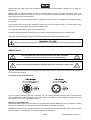
The symbol
---m
determines the minimum distance from lighted objects. The minimum distance
between light-output and the illuminated surface must be more than 0.1 meters.
This device is only allowed for an installation via the mounting bracket. In order to safeguard sufficient
ventilation, leave 50 cm of free space around the device.
The housing must never touch surrounding surfaces or objects.
Make sure that the area below the installation place is blocked when rigging, derigging or servicing the
fixture.
Always fix the fixture with an appropriate safety bond.
The maximum ambient temperature T
a
= 45° C must never be exceeded.
Operate the device only after having become familiarized with its functions. Do not permit operation by
persons not qualified for operating the device. Most damages are the result of unprofessional operation!
Never use solvents or aggressive detergents in order to clean the device! Rather use a soft and damp cloth.
Please use the original packaging if the device is to be transported. Make sure that you pack the device in
the original state.
Please consider that unauthorized modifications on the device are forbidden due to safety reasons!
If this device will be operated in any way different to the one described in this manual, the product may suffer
damages and the guarantee becomes void. Furthermore, any other operation may lead to dangers like short-
circuit, burns, electric shock, crash etc.
0!("=)"55)$!0!/"!
Features:
+3*=4!0:
• 1 row of 8 glass lenses
• Equipped with 6x 3 W LEDs with RGBAWP colors
• Each lens can be controlled individually via DMX
• DMX512 control via regular DMX controller
• 3 or 10 DMX channels selectable for numerous applications
• DMX-controlled operation or stand-alone operation with Master/Slave function
• Sound controlled via built-in microphone
• Strobe effect
• Auto mode
• Internal programs
• Master/Slave function
• Addressing and setting via control panel with 4-digit LED display and four operating buttons
• Rugged, compact housing in a striking design
• Innumerable uses
• Ideal for bands, stages or solo entertainers
• Switch-mode power supply for operation between 100 and 240 Volts
• Ready for connection via enclosed IEC power cord with safety plug
• Additional controlling possibility via the EUROLITE IR-7 remote control, included in delivery
• DMX control via every standard DMX controller
• Mounting bracket for installation on a truss system included
• Locking possibility at the mounting bracket

00091062.DOC, Version 1.1
20/28
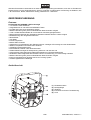
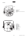
Overview:
A7B Fixation screw
A;B Bracket
A'B Housing
ACB Infrared sensor for the remote control
A1B Lens
A2B Display
A6B Mode button
A>B Up button
A?B Down button
A78BEnter button
A77BMicrophone
A7;BAttachment eyelet
A7'BDMX in
A7CBDMX out
A71BPower output
A72BFuse
A76BPower supply

00091062.DOC, Version 1.1
21/28
"()3443)"5
5
03!)54"!
Please consider the EN 60598-2-17and the respective national standards during the installation!
The installation must only be carried out by an authorized dealer!
The installation of the device has to be built and constructed in a way that it can hold 10 times the weight for
1 hour without any harming deformation.
The installation must always be secured with a secondary safety attachment, e.g. an appropriate catch net.
This secondary safety attachment must be constructed in a way that no part of the installation can fall down
if the main attachment fails.
When rigging, derigging or servicing the device staying in the area below the installation place, on bridges,
under high working places and other endangered areas is forbidden.
The operator has to make sure that safety-relating and machine-technical installations are approved by an
expert before taking into operation for the first time and after changes before taking into operation another
time.
The operator has to make sure that safety-relating and machine-technical installations are approved by an
expert after every four year in the course of an acceptance test.
The operator has to make sure that safety-relating and machine-technical installations are approved by a
skilled person once a year.
=@
The device should be installed outside areas where persons may walk by or be seated.
IMPORTANT! OVERHEAD RIGGING REQUIRES EXTENSIVE EXPERIENCE, including (but not limited to)
calculating working load limits, installation material being used, and periodic safety inspection of all
installation material and the device. If you lack these qualifications, do not attempt the installation yourself,
but instead use a professional structural rigger. Improper installation can result in bodily injury and or
damage to property.
The device has to be installed out of the reach of people.
If the device shall be lowered from the ceiling or high joists, professional trussing systems have to be used.
The device must never be fixed swinging freely in the room.
@ Devices in hanging installations may cause severe injuries when crashing down! If you have
doubts concerning the safety of a possible installation, do NOT install the device!
Before rigging make sure that the installation area can hold a minimum point load of 10 times the device's
weight.
DANGEROFFIRE!
Wheninstallingthedevice,makesurethereisnohighly-inflammable
material(decorationarticles,etc.)withinadistanceofmin.0.5m.
Mount the device to your trussing system using an appropriate clamp.
For overhead use, always install an appropriate safety bond.
You must only use safety bonds and quick links complying with DIN 56927, shackles complying with DIN EN
1677-1 and BGV C1 carbines. The safety bonds, quick links, shackles and the carbines must be sufficiently

00091062.DOC, Version 1.1
22/28
dimensioned and used correctly in accordance with the latest industrial safety regulations (e. g. BGV C1,
BGI 810-3).
= @ for overhead rigging in public or industrial areas, a series of safety instructions have to be
followed that this manual can only give in part. The operator must therefore inform himself on the current
safety instructions and consider them.
The manufacturer cannot be made liable for damages caused by incorrect installations or insufficient safety
precautions!
Pull the safety bond through the attachment eyelet and over the trussing system or a safe fixation spot.
Insert the end in the quick link and tighten the safety screw.
The maximum drop distance must never exceed 20 cm.
A safety bond which already held the strain of a crash or which is defective must not be used again.
Adjust the desired inclination-angle via the mounting-bracket and tighten the fixation screws.
DANGERTOLIFE!
Beforetakingintooperationforthefirsttime,theinstallationhastobeapprovedbyanexpert!
0,917;
)D
D &
= D &
Only use a DMX cable and 3-pin XLR plugs and connectors in order to connect the controller with the fixture
or one fixture with another.
594@
If you are using controllers with this occupation, you can connect the DMX output of the controller directly
with the DMX input of the first device in the DMX chain. If you wish to connect DMX controllers with other
XLR outputs, you need to use adapter cables.
+ 0,9@
Connect the DMX output of the first device in the DMX chain with the DMX input of the next device. Always
connect one output with the input of the next device until all devices are connected.
@At the last fixture, the DMX cable has to be terminated. Plug the terminator with a 120
Ω
resistor
between Signal (–) and Signal (+) in the DMX output of the last fixture.

00091062.DOC, Version 1.1
23/28
,G(
The master/slave operation enables that several devices can be synchronized and controlled by one master
device.
On the rear panel of the device you can find an XLR jack and an XLR plug, which can be used for
connecting several devices.
Choose the device which is to control the effects. This device then works as master device and controls all
other slave devices, which are to be connected to the master device via a DMX-cable. Connect the OUT jack
with the IN plug of the next device.
Set the Master device to the desired Master mode, as described in chapter Control Board. Set slave mode
for all slave devices.
On the rear panel, there is an IEC socket (Power Out). Connect the output with the input of the next fixture
until all fixtures are connected.
3@It is recommended to renew the connection with the power mains after every > devices.
Connect the device to the mains with the enclosed power supply cable.
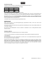
): @
=
"
Brown Live L
Blue Neutral N
Yellow/Green Earth
The earth has to be connected!
If the device will be directly connected with the local power supply network, a disconnection switch with a
minimum opening of 3 mm at every pole has to be included in the permanent electrical installation.
The device must only be connected with an electric installation carried out in compliance with the IEC-
standards. The electric installation must be equipped with a Residual Current Device (RCD) with a maximum
fault current of 30 mA.
Lighting effects must not be connected to dimming-packs.
5=!3)"5
After you connected the spot to the mains, the EUROLITE LED FE-700 Flower effect starts running.
The display lights up and you can choose the desired mode via the buttons MODE, ENTER, UP and DOWN.
The device has two operating modes. It can be operated in stand-alone or in DMX-controlled mode.
(:
In the stand-alone mode, the device can be used without controller.
Disconnect the device from the controller. Please refer to the instructions under chapter Control Board.
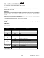
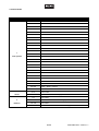
+
The Control Board offers several features: you can simply set the starting address or run the pre-
programmed program.

00091062.DOC, Version 1.1
24/28
The main menu is accessed by pressing Mode until the display is lit. Browse through the menu by pressing
Up or Down. Press Enter in order to select the desired menu. You can change the selection by pressing Up
or Down. Press Enter in order to confirm. You can leave every mode by pressing Mode. The functions
provided are described in the following sections.
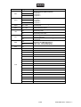
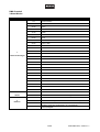
, = 0
Auto
Au-1
3A,B
Program 1
Program 2
Program 3
Au-2
Au-3
Sond
So-1
( A,B
Program 1
Program 2
Program 3
So-2
So-3
Sped SP 1—SP9
(
(increasing)
Sens Se 1—Se9
,
Sound controlled mode
(increasing)
Sile
OFF
Program continues automatically during periods
without music or bass-beat
ON
Program does not automatically continue during
periods without music or bass-beat
InFr
ON
"
:enable
OFF
"
:disenable
Addr
3CH
(0,9 A( B
0,9
d 001~d 512 3 channels DMX mode
d 001~d 512 10 channels DMX mode
10CH
Slav Slav
(
Colo
( A,B
C1 Red
C2 Green
C3 Blue
C4 White
C5 Amber
C6 Pink
C7 Red + Green
C8 Green + Blue
C9 Blue + White
C10 White + Amber
C11 Amber + Pink
C12 Red + Blue + Pink
C13 Green + Amber
C14 Red + Green + Blue
C15 Red + Green + Blue + White

00091062.DOC, Version 1.1
25/28
0,9:5)544!05=!3)"5
You can control the devices individually via your DMX-controller.
0,9:,
The device has two different DMX channel modes. The Control Board allows you, as described below, to
assign the DMX channel mode.
3
Press the MODE button until the display shows 3& Press ENTER to confirm. You can now set the desired
address via the UP or DOWN buttons. Press ENTER to confirm. The Control Board allows you to assign the
DMX fixture address, which is defined as the first channel from which the device will respond to the
controller.
Please, be sure that you don’t have any overlapping channels in order to control each device correctly and
independently from any other fixture on the DMX-chain.
If several devices are addressed similarly, they will work synchronically.
@
After having addressed the LED FE-700 Flower effect, you may now start operating it via your lighting
controller.
0,9
78
/ @
7
0-255 Red
;
0-255 Green
'
0-255 Blue
C
0-255 White
1
0-255 Amber
2
0-255 Pink
6
(
0-10 No function
11-255 Strobe with increasing speed
>
0-9 No rotation
10-127 Clockwise rotation with increasing speed
128-138 No rotation
139-255 Counter clockwise rotation with increasing speed
?
=0,9
0-9 No function
10-200 Auto program by DMX
201-255 Sound program by DMX
78
(0,9
0-255 Auto program with increasing spead

00091062.DOC, Version 1.1
26/28
'
/ @ @
7
0-9 No function
10-19 Red
20-29 Green
30-39 Blue
40-49 White
50-59 Amber
60-69 Pnk
70-79 Red + Green
80-89 Green +Blue
90-99 Blue + White
100-109 White + Amber
110-119 Amber + Pink
120-129 Red + Pink
130-139 Green + Amber
140-149 Red + Green + Blue
150-159 Red + Green + Amber
160-169 Red + Green + Pink
170-179 Red + Blue + Pink
180-189 Blue + White + Pink
190-199 Blue+ White + Amber
200-209 Green + Blue+ White
210-219 Green + Blue + Amber
220-229 Red+ Blue + White
230-239 Red+ Blue + Amber
240-249
Red + White + Amber
250-255 Green + White + Pink
;
(
0-10 No function
11-255 Strobe effect with increasing speed
'
0-9 No rotation
10-127 Rotation clockwise with increasing speed
128-138 No rotation
139-255 Rotation counterclockwise with increasing speed

00091062.DOC, Version 1.1
27/28
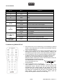
!%54")!":6
7
The device must be activated for remote control. For this, under
menu item InFr, press ENTER button to confirm activation.
;
When actuating a button, always hold the remote control in the
direction of the sensor. There must be visual connection between
the remote control and the sensor.
'
The remote control is supplied with a battery inserted. An insulating
foil between the battery and the battery contacts prevents the
battery from being discharged during storage. Prior to the first
operation remove the foil from the battery support on the rear side
of the remote control. Otherwise operation of
the remote control is not possible.
C
If the range of the remote control decreases
(10 meters as a maximum), replace the
battery. For this purpose, on the rear side of the remote control
press the small bar with the groove to the right and at the same
time remove the battery support. For operation, one 3 V button cell
type CR 2025 is required. When inserting, pay attention that the
positive pole of the button cell shows upwards in the support.
3%)"5
Danger of explosion when battery is replaced improperly. Only replace by the same type.
Please dispose of old and used batteries properly. Batteries are hazardous waste and should
not be disposed of with regular domestic waste!
& (7 (; (' 0
7 +435%)
+435%)
+
; ()5+! ()5+! HG:
(
-
available for the buttons
AUTO/SOUND/FADE/MANUAL/R/G/B/A/UV/W/0 - 9
' (=!!0 (=!!0 HG:
(
Internal programs
C (!(")"/")< (!(")"/")< HG:
,
Sound controlled mode
1 I I HG: (0,9
2 HG:
3%)5G(5%0G
()5+!G
(=!!0G
(!(")"/")<GI
G30!G
,3%34G
GGG+G3G%/G*
HG: "G0
6 3%)5
7
3%)5 HG: "
K; 3%)5 (=!!0 HG:
Desired speed
K'
3%)5
()5+!
HG
:
Strobe effect
> (5%0
7
(5%0 HG: (
K;
(5%0
(!(")"/")<
HG
:
Microphone sensitivity
K' (5%0 ()5+! HG:
Strobe effect
? ,3%34
7
,3%34
R/G/B
K; ,3%34 HG:
Manual Setting of color presets
K' ,3%34 ()5+! HG:
Strobe speed

00091062.DOC, Version 1.1
28/28
4!3"30,3")!3!
The operator has to make sure that safety-relating and machine-technical installations are inspected by an expert after
every four years in the course of an acceptance test.
The operator has to make sure that safety-relating and machine-technical installations are inspected by a skilled person
once a year.
The following points have to be considered during the inspection:
1) All screws used for installing the devices or parts of the device have to be tightly connected and must not be corroded.
2) There must not be any deformations on housings, fixations and installation spots (ceiling, suspension, trussing).
3) The electric power supply cables must not show any damages, material fatigue (e.g. porous cables) or sediments.
Further instructions depending on the installation spot and usage have to be adhered by a skilled installer and any
safety problems have to be removed.
Disconnectfrommainsbeforestartingmaintenanceoperation!
DANGERTOLIFE!
We recommend a frequent cleaning of the device. Please use a soft lint-free and moistened cloth. Never use alcohol or
solvents!
There are no serviceable parts inside the device except for the fuse. Maintenance and service operations are only to be
carried out by authorized dealers.
If the fine-wire fuse of the device fuses, only replace the fuse by a fuse of same type and rating.
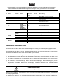
+ D &
=@
( 1: Open the fuseholder on the rear panel with a fitting screwdriver.
(;@ Remove the old fuse from the fuseholder.
('@ Install the new fuse in the fuseholder.
(C@ Replace the fuseholder in the housing.
Should you need any spare parts, please use genuine parts.
If the power supply cable of this device becomes damaged, it has to be replaced by a special power supply cable
available at your dealer.
Should
you have further questions, please contact your dealer.
)!$"34(=!""3)"5(
Power supply: 100-240 V AC, 50/60 Hz ~
Power consumption: 24 W
DMX-control-channels: 3/10
DMX-512-connection: 3-pin XLR
Sound-control: via built-in microphone
Maximum ambient temperature T
a
: 45° C
Maximum housing temperature T
C
: 50° C
Min.distance from flammable surfaces: 0.5 m
Min.distance to lighted object: 0.1 m
Fuse: T 1 A, 250V
LED type:
3 W LED RGBAWP
Number of LEDs:
6
Dimensions (LxWxH): 200 x 300 x 310 mm
Weight: 3.2 kg
3
@
&@
TPC-10 Coupler, silver 59006856
Safety bond AG-5 3x600mm up to 5kg 58010360
XLR cable 3pin 3m black 3022047N
XLR plug 3pin 110 Ohm 30208430
SB-10 Soft bag 30130500
IR-7 Remote control 50530561
= @3 M&;6&8>&;871
-
 1
1
-
 2
2
-
 3
3
-
 4
4
-
 5
5
-
 6
6
-
 7
7
-
 8
8
-
 9
9
-
 10
10
-
 11
11
-
 12
12
-
 13
13
-
 14
14
-
 15
15
-
 16
16
-
 17
17
-
 18
18
-
 19
19
-
 20
20
-
 21
21
-
 22
22
-
 23
23
-
 24
24
-
 25
25
-
 26
26
-
 27
27
-
 28
28


EuroLite LED FE-700 User manual
- Category
- Stroboscopes & disco lights
- Type
- User manual
Ask a question and I''ll find the answer in the document
Finding information in a document is now easier with AI
in other languages
- Deutsch: EuroLite LED FE-700 Benutzerhandbuch
Related papers
-
EuroLite BR-200 User manual
-
-
-
-
EuroLite LED Disco Strobe User manual
-
-
-
-
-
Other documents
-
 EuroLite Cases 4-channel DMX dimmer pack User manual
-
Renkforce DL-LED107S Owner's manual
-
Cameo ROTOFEVER CLRF User manual
-
Fun Generation ClubFX-1 Beam Flower 40W Quad Owner's manual
-
 Ape Labs LED Mobilight 4 6er Tourpack Owner's manual
-
Varytec BAT.BALL RGBWAP User manual
-
-
Rutenbeck PP-Cat U basic User manual
-
RetroSound FB-RETRO-LF Owner's manual
-
e+p CST 2 Datasheet

