Page is loading ...

EN
www.carlisle.com Manual PN: 341164EN REV A
PRODUCT MANUAL
QUICKHEAT HOSE

EN
www.carlisle.com Manual PN: 341164EN REV A
2
Page intenonally le blank

EN
www.carlisle.com Manual PN: 341164EN REV A
3
COMPLIANCE
Item Descripon
2006/42/EC Machinery Direcve
2014/35/EU Low Voltage Direcves
2011/65/EU RoHS Direcve with Amendment 2015/863
COMPLIANCE
Compliance to the following standards is indicated by the corresponding mark on the product.
COMPLIANCE PENDING
EC Direcves
Item Descripon
ISO 12100 Machinery Safety
EN60204-1 Safety of Machinery – Electrical Equipment
IEC 63000 New Harmonized Standard to Demonstrate RoHS Compliance
Safety Standards
Item Descripon
TUV NNNN
FCC

EN
www.carlisle.com Manual PN: 341164EN REV A
4
Page intenonally le blank

EN
www.carlisle.com Manual PN: 341164EN REV A
5
CONTENTS
SAFETY .................................................................................................................................................. 6
INTRODUCTION .................................................................................................................................... 15
PRODUCT FEATURES .......................................................................................................................................... 15
SYSTEM COMPONENTS ...................................................................................................................................... 16
INSTALLATION ...................................................................................................................................... 21
REQUIRED TOOLS AND HARDWARE .................................................................................................................. 21
PROPORTIONER-TO-HOSE CONNECTIONS......................................................................................................... 21
HOSE-TO-HOSE CONNECTIONS .......................................................................................................................... 23
HOSE-TO-GUN CONNECTIONS ........................................................................................................................... 25
HOSE USAGE ........................................................................................................................................ 26
KEY OPERATIONAL REQUIREMENTS .................................................................................................................. 26
FIBER OPTIC CABLE LED INDICATORS ................................................................................................................ 26
PRODUCT TROUBLESHOOTING ............................................................................................................ 27
PRODUCT MAINTENANCE .................................................................................................................... 29
REGULAR MAINTENANCE PROCEDURES AND RECOMMENDATIONS ............................................................... 29
SPARE PARTS & REPAIR KITS .............................................................................................................................. 30
HOSE SECTION REPLACEMENT .......................................................................................................................... 31
WARRANTY .......................................................................................................................................... 37
CONTENTS

EN
www.carlisle.com Manual PN: 341164EN REV A
6
SAFETY
SAFETY
SAFETY PRECAUTIONS
Before operang, maintaining or servicing any Carlisle system, read
and understand all of the technical and safety literature for your
products. This manual contains informaon that is important for you
to know and understand. This informaon relates to USER SAFETY and
PREVENTING EQUIPMENT PROBLEMS.
To help you recognize this informaon, we use the following symbols.
Please pay parcular aenon to these secons.
WARNING
A WARNING! states informaon to alert you to a situaon that might
cause serious injury if instrucons are not followed.
WARNING
The user MUST read and be familiar with the Safety Secon in this
manual and the Ransburg safety literature therein idened.
This equipment is intended to be used by trained personnel ONLY.
This manual MUST be read and thoroughly understood by ALL
personnel who operate, clean or maintain this equipment! Special care
should be taken to ensure that the WARNINGS and safety
requirements for operang and servicing the equipment are followed.
The user should be aware of and adhere to ALL local building and re
codes and ordinances as well as any applicable country safety
standards, prior to installing, operang, and/or servicing this
equipment.
WARNING
The hazards shown on the following pages may occur during the
normal use of this equipment.
CAUTION
A CAUTION! states informaon that tells how to prevent damage to
equipment or how to avoid a situaon that might cause minor injury.
NOTE
A NOTE is informaon which is relevant to the procedure in progress.
While this manual lists standard specicaons and service procedures,
some minor deviaons may be found between this literature and your
equipment. Dierences in local codes and plant requirements, material
delivery requirements, etc., make such variaons inevitable. Compare
this manual with your system installaon drawings and appropriate
equipment manuals to reconcile such dierences.

EN
www.carlisle.com Manual PN: 341164EN REV A
7
SAFETY
Connued in next page...
Read the following warnings before using this equipment
WARNING
READ THE MANUAL read and
all safety, and maintenance in
the
TIP/CRUSH HAZARD Do not p unit. In mobile or seismic installaons be
sure unit is secured to oor and wall per instrucons.
TRAINING All must be before
equipment. STATIC CHARGE Fluid may develop a stac charge that must be
dissipated through proper grounding of the equipment, objects to be
sprayed and all other electrically conducve objects in the dispensing
area. Improper grounding or sparks can cause a hazardous condion and
result in re, explosion or electric shock and other serious injury.
AUTOMATIC EQUIPMENT Automac equipment may start suddenly
without warning.
EQUIPMENT HAZARD can cause the
to or start and result in
injury.
LOCK OUT / TAG-OUT Failure to de-energize, disconnect, lock out and
tag-out all power sources before performing equipment maintenance
could cause serious injury or death.
PRESSURE RELIEF PROCEDURE Always follow the pressure relief
procedure in the equipment instrucon manual.
WEAR RESPIRATOR Toxic fumes can cause serious injury or death if
inhaled. Wear a respirator as recommended by the uid and solvent
TOXIC FLUID & FUMES Hazardous uid or toxic fumes can cause serious
injury or death if splashed in the eyes or on the skin, inhaled, injected or
swallowed. LEARN and KNOW the specic hazards or the uids you are
ELECTRICAL SHOCK HAZARD Disconnect all power sources before
accessing any electrical connecons in the Control Module, Fluid
Modules, or Hoses. Equipment must be serviced by trained personnel
INSPECT THE EQUIPMENT DAILY Inspect the equipment for worn or
broken parts on a daily basis. Do not operate the equipment if you are
uncertain about its condion.
KEEP EQUIPMENT GUARDS IN PLACE Do not operate the equipment if
the safety devices have been removed.
KNOW WHERE AND HOW TO SHUT OFF THE EQUIPMENT IN CASE OF
AN EMERGENCY
WEAR SAFETY GLASSES Failure to wear safety glasses with side shields
could result in serious eye injury or blindness.
FIRE AND EXPLOSION HAZARD Improper equipment grounding, poor
venlaon, open ame or sparks can cause a hazardous condion and
result in re or explosion and serious injury.
MEDICAL ALERT Any injury caused by high pressure liquid can be serious.
If you are injured or even suspect an injury:
• Go to an emergency room immediately.
• Tell the doctor you suspect an injecon injury.
• Show the doctor this medical informaon or the medical alert card
provided with your airless spray equipment.
• Tell the doctor what kind of uid you were spraying or dispensing.
• Refer to the Material Safety Data Sheet for specic informaon.
NEVER MODIFY THE EQUIPMENT Do not modify the equipment unless
the manufacturer provides wrien approval.

EN
www.carlisle.com Manual PN: 341164EN REV A
8
NOISE HAZARD You may be injured by loud noise. Hearing protecon
may be required when using this equipment.
PROJECTILE HAZARD You may be injured by venng liquids or gases that
are released under pressure, or ying debris.
PROP 65 WARNING: This product contains chemicals known to the State
of California to cause cancer and birth defects or other reproducve
harm.
It is the of the to this to the of the
PINCH POINT HAZARD Moving parts can crush and cut. Pinch points are
basically any areas where there are moving parts.
Read the following warnings before using this equipment
WARNING
GET IMMEDIATE MEDICAL ATTENTION To prevent contact with the uid,
please note the following:
• Never point the gun/valve at anyone or any part of the body.
• Never put hand or ngers over the spray p.
• Never aempt to stop or deect uid leaks with your hand, body,
glove or rag.
• Always have the p guard on the spray gun before spraying.
• Always ensure that the gun trigger safety operates before spraying.
• Always lock the gun trigger safety when you stop spraying.

EN
www.carlisle.com Manual PN: 341164EN REV A
9
AREA
Tells where hazards may
occur
HAZARD
Tells what the hazard is
SAFEGUARDS
Tells how to avoid the hazard
Spray Area High
Voltage
Equipment
Electrical Discharge
There is a high voltage device that can induce
an electrical charge on ungrounded objects
which is capable of igning coang materials.
Inadequate grounding will cause a spark
hazard. A spark can ignite many coang
materials and cause a re or explosion.
Parts being sprayed and operators in the spray area must be properly
grounded.
Parts being sprayed must be supported on conveyors or hangers that
are properly grounded. The resistance between the part and earth
ground must not exceed 1 meg ohm. (Refer to NFPA-33.)
Operators must be grounded. Rubber soled insulang shoes should
not be worn. Grounding straps on wrists or legs may be used to
assure adequate ground contact.
Operators must not be wearing or carrying any ungrounded metal
objects.
When using an electrostac handgun, opera- tors must assure contact
with the handle of the applicator via conducve gloves or gloves with
the palm secon cut out.
NOTE: REFER TO NFPA-33 OR SPECIFIC COUNTRY SAFETY CODES
REGARDING PROPER OPERATOR GROUNDING.
All electrically conducve objects in the spray area, with the
excepon of those objects re- quired by the process to be at high
voltage, must be grounded. Grounded conducve ooring must be
provided in the spray area.
Always turn o the power supply prior to ushing, cleaning, or
working on spray system equipment.
Unless specically approved for use in hazardous locaons, all
electrical equipment must be located outside Class I or II, Division 1 or
2 hazardous areas, in accordance with NFPA-33.
Avoid installing an applicator into a uid system where the solvent
supply is ungrounded.
Do not touch the applicator electrode while it is energized.

EN
www.carlisle.com Manual PN: 341164EN REV A
10
AREA
Tells where hazards may
occur
HAZARD
Tells what the hazard is
SAFEGUARDS
Tells how to avoid the hazard
Electrical
Equipment
Electrical Discharge
High voltage equipment is ulized in the
process. Arcing in the vicinity of ammable or
combusble materials may occur. Personnel
are exposed to high voltage during operaon
and maintenance.
Protecon against inadvertent arcing that may
cause a re or explosion is lost if safety circuits
are disabled during operaon.
Frequent power supply shutdown indicates a
problem in the system which requires
correcon.
An electrical arc can ignite coang materials
and cause a re or explosion.
Unless specically approved for use in hazardous locaons, the power
supply, control cabinet, and all other electrical equipment must be
located outside Class I or II, Division 1 and 2 hazardous areas in
accordance with NFPA-33 and EN 50176.
Turn the power supply OFF before working on the equipment.
Test only in areas free of ammable or combusble material.
Tesng may require high voltage to be on, but only as instructed.
Producon should never be done with the safety circuits disabled.
Before turning the high voltage on, make sure no objects are within
the sparking distance.
Toxic
Substances
Chemical Hazard
Certain materials may be harmful if inhaled, or
if there is contact with the skin.
Follow the requirements of the Safety Data Sheet supplied by coang
material manufacturer.
Adequate exhaust must be provided to keep the air free of
accumulaons of toxic materials.
Use a mask or respirator whenever there is a chance of inhaling
sprayed materials. The mask must be compable with the material
being sprayed and its concentraon. Equipment must be as
prescribed by an industrial hygienist or safety expert, and be NIOSH
approved.
Spray Area Explosion Hazard —
Incompable Materials
Halogenated hydrocarbon solvents for
example: methylene chloride and 1,1,1, -
Trichloroethane are not chemically compable
with the aluminum that might be used in many
system components.
The chemical reacon caused by these solvents
reacng with aluminum can become violent
and lead to an equipment explosion.
Spray applicators require that aluminum inlet ngs be replaced with
stainless steel.
Aluminum is widely used in other spray applicaon equipment - such
as material pumps, regulators, triggering valves, etc. Halogenated
hydrocarbon solvents must never be used with aluminum equipment
during spraying, ushing, or cleaning. Read the label or data sheet for
the material you intend to spray. If in doubt as to whether or not a
coang or cleaning material is compable, contact your coang
supplier. Any other type of solvent may be used with aluminum
equipment.
SAFETY

EN
www.carlisle.com Manual PN: 341164EN REV A
11
SAFETY
AREA
Tells where hazards may
occur
HAZARD
Tells what the hazard is
SAFEGUARDS
Tells how to avoid the hazard
Toxic
Substances
ISOCYANATE Condions Spraying or dispensing uids that contain isocyanates creates
potenally harmful mists, vapors, and atomized parculates. Workers
exposed to isocyanates can develop a range of short and long-term
health problems.
Read and understand the uid manufacturer’s warnings and Safety
Data Sheet (SDS) to know specic hazards and precauons related to
isocyanates.
Use of isocyanates involves potenally hazardous procedures. Do not
spray with this equipment unless you are trained, qualied, and have
read and understood the informaon in this manual and in the uid
manufacturer’s applicaon instrucons and SDS.
Use of incorrectly maintained or mis-adjusted equipment may result
in improperly cured material which could cause o-gassing and
oensive odors. Equipment must be carefully maintained and
operated according to instrucons in the manual.
To prevent inhalaon of isocyanate mists, vapors and atomized
parculates, everyone in the work area must wear appropriate
respiratory protecon. Always wear a properly ng respirator,
which may include a supplied-air respirator. Venlate the work area
according to instrucons in the uid manufacturer’s SDS.
Avoid all skin contact with isocyanates. Everyone in the work area
must wear chemically impermeable gloves, protecve clothing and
foot coverings as recommended by the uid manufacturer and local
regulatory authority. Follow all uid manufacturer recommendaons,
including those regarding handling of contaminated clothing. Aer
spraying, wash hands and face before eang or drinking.
Hazard from exposure to isocyanates connues aer spraying.
Anyone without appropriate personal protecve equipment must stay
out of the work area during applicaon and aer applicaon for the
me period specied by the uid manufacturer. Generally this me
period is at least 24 hours.
Warn others who may enter work area of hazard from exposure to
isocyanates. Follow the recommendaons of the uid manufacturer
and local regulatory authority. Posng a sign outside the work area is
recommended.

EN
www.carlisle.com Manual PN: 341164EN REV A
12
AREA
Tells where hazards may
occur
HAZARD
Tells what the hazard is
SAFEGUARDS
Tells how to avoid the hazard
Personal
Protecve
Equipment
Always wear appropriate personal protecve
equipment and cover all skin when spraying,
servicing equipment, or when in the work area
Protecve equipment helps prevent serious injury, including long-
term exposure; inhalaon of toxic fumes, mists or vapors; allergic
reacon; burns; eye injury and hearing loss. This protecve
equipment includes but is not limited to:
• A properly ng respirator, which may include a supplied-air
respirator
• Chemically impermeable gloves
• Protecve clothing and foot coverings as recommended by the
uid manufacturer and local regulatory authority
• Protecve eyewear
• Hearing protecon.
Toxic
Substances
Toxic Fluid or Fumes Hazard Toxic uids or fumes can cause serious injury or death if splashed in
the eyes or on skin, inhaled or swallowed.
Read Safety Data Sheet (SDS) for handling instrucons and to know
the specic hazards of the uids you are using, including the eects of
long-term exposure.
When spraying, servicing equipment, or when in the work area,
always keep work area well venlated and always wear appropriate
personal protecve equipment. See Personal Protecve Equipment
warnings in this manual.
Store hazardous uid in approved containers and dispose of it
according to applicable guidelines.
SAFETY

EN
www.carlisle.com Manual PN: 341164EN REV A
13
SAFETY
AREA
Tells where hazards may
occur
HAZARD
Tells what the hazard is
SAFEGUARDS
Tells how to avoid the hazard
Spray Area Skin Injecon Hazard High-pressure uid from gun, hose or ng leaks, or ruptured
components may pierce skin. This may look like just a cut, but it is a
serious injury that can result in amputaon. Get immediate medical
treatment.
Do not point the spray gun at anyone or at any part of the body.
Do not put your hand or ngers over the gun uid nozzle or any
ngs in the hose or proporoner.
Do not aempt to stop or deect leaks with your hand, body, glove,
or rag.
Do not “blow back” uid; this is not an air spray system.
Follow Pressure Relief Procedure, before cleaning, checking, or
servicing equipment.
Use lowest possible pressure when purging, recirculang, or
troubleshoong.
Check hoses, couplings, and ngs daily. Service or replace leaking,
worn, or damaged parts immediately. High pressure hose secons
cannot be recoupled; replace the hose secon.
Equipment Equipment Misuse Hazard Misuse can cause serious injury or death.
For professional use only.
Use equipment only for its intended purpose. Call your Carlisle
distributor for informaon.
Read manuals, warnings, tags, and labels before operang
equipment. Follow instrucons.
Check equipment daily. Repair or replace worn or damaged parts
immediately.
Do not alter or modify equipment. Use only Carlisle parts and
accessories.
Do not exceed the maximum working pressure or temperature rang
of the lowest rated system component. See Technical Data in all
equipment manuals.
Use uids and solvents that are compable with equipment weed
parts.
Route hoses and cables away from trac areas, sharp edges, moving
parts, and hot surfaces.
Do not use hoses to pull equipment.
Comply with all applicable safety regulaons.

EN
www.carlisle.com Manual PN: 341164EN REV A
14
Page intenonally le blank

EN
www.carlisle.com Manual PN: 341164EN REV A
15
INTRODUCTION
INTRODUCTION
The Carlisle IntelliSpray Spray Polyurethane Foam (SPF) system consists of the IS40 Proporoner, QuickHeat Hose, and ST1 Spray Gun. The
IntelliSpray system has been designed for ease of use, increased producvity, “best in class” process control, easy service, and real-me rao
control.
The QuickHeat hose has roughly double the heang power compared to most other SPF hoses and directly heats the uid from inside the hose,
which results in fast and ecient uid heang, even in cold climate condions. QuickHeat hoses have embedded temperature and pressure
sensors, independent A & B hose heang, and up to six independent heang zones to improve temperature control. QuickHeat hoses provide
sensor power and signal communicaon without cables or connectors, providing reliability and reducing failure opons. QuickHeat hoses include
a snag and abrasion resistant outer hose wrap that is sealed with industrial-grade Hook & Loop material to allow individual A or B side hose
replacement.
The IS40 proporoner is specically designed to use Carlisle QuickHeat Hoses. These hoses contain high-power internal electric heang cables,
ensuring that all of the heang energy is transmied directly to the uid. QuickHeat hoses are provided in 100, 150 or 200 foot (30, 45, or 60m)
lengths. Heated whip hoses (Smart Ends) are available in 20 and 40 foot (6 or 12m) lengths. Insulated whips are available in 6 or 10 foot (2 or 3m)
lengths. Each length of a heated hose begins with a uid manifold or “modem” that contains pressure and/or temperature sensors, heater cable
connectors, and electronics used to send informaon over the hose to the system’s Control Module. With this approach, no sensor power or
communicaon cables are required, which are a common source of hose failures in other systems. It also provides the proprietary architecture for
two way communicaon between the hose, proporoner and remote devices .
PRODUCT FEATURES
Fast and reliable heat
Independent A & B embedded heater wire submerged in hose uid achieving > 100˚F (37˚C) DeltaT in under 15 minutes on average.
Real-me system control
Pressure and temperature data communicated and controlled within hose to spray gun to maximize control and accuracy.
Cut service costs
Reduced need for service with fully poed electronics/sensors and the ability to replace A & B side independently when needed.
Reduced electrical connecons
Resulng in less maintenance issues.
More heat control and less risk
Independent heat sensors allow system to adjust temperature.
Lighter and more exible hoses for less sprayer fague
SYSTEM COMPONENTS

EN
www.carlisle.com Manual PN: 341164EN REV A
16
INTRODUCTION
The QuickHeat hose has the following components:
• Poed modem (1 per hose segment)
• Material Hoses (1 per material and per segment)
• Heater wires (1 per material and per segment)
• Heater power cables (1 per material and per segment)
• Master hose low voltage (24 VDC) power cable
• Master hose EtherCAT cable
• Fiber Opc status light cable
• Air hose (one per hose segment)
Hose Conguraons
Depending on the length needed for the enre hose system, you can set it up in 2 dierent conguraons. The hose length cannot exceed 350
for either the IS30 or IS40 systems.
Hose Pneumac, Hydraulic and Power connecons
The QuickHeat hose structure and connecons vary depending on the conguraon selected.
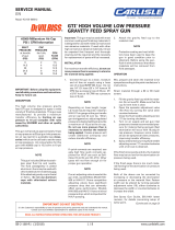
1. Proporoner Control Module
2. Material A Fluid Module
3. Material B Fluid Module
4. Zone 1, 2, 3 & 4 Heater Wire Power Cable
5. Zone 1 & 2 Heater Wire Power Cable
6. Zone 3, 4, 5 & 6 Heater Wire Power Cable
7. Hose Segment Modem
8. Power Cable Splier
9. Material A & B Circuit board Power Cable
NOTE
Communicaon from modem to modem (aer the Master) travels
through the communicaon layer in the hose (referenced in the
“Hose Layer” secon).

EN
www.carlisle.com Manual PN: 341164EN REV A
17
INTRODUCTION
1
2
3
4
7
9
1
2
3
5
6
9
8
9
8
7
7
7 7

EN
www.carlisle.com Manual PN: 341164EN REV A
18
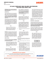
Poed Modem Structure
Each hose segment has a poed modem at the start of the segment. The modems may dier depending on whether they are part of a master,
mid or smart-end segment. The dierences are included in the installaon secon of this manual. The B-side of the modem below is shown
1. Material A input
2. Material B input
3. Material temperature probes (A & B) (not shown
in diagram below)
4. Fluid heater cables
5. Fluid pressure sensors
6. Circuit boards
7. Material A output
8. Fiber opc status cable
1
2
3
5
6
7
8
9
INTRODUCTION
without a cover for reference.
Benets
• Fully ruggedized poed electronics
• Fully sealed set of uid ngs
• Built-in mul-colored LED and beropc feedback for system status
• High-resoluon process control and communicaon electronics
• Independently-replaceable A and B side design
• Minimized connecons
4

EN
www.carlisle.com Manual PN: 341164EN REV A
19
• Independent pressure and temperature sensing control
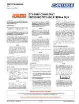
Hose Layers
1. Santoprene
2. Proprietary communicaon layer
3. Thermoplasc Urethane (TPU)
4. Fiber braid
5. Nylon core
5 4 3 2 1
Item Details
Dimensions (Length)
Master hose: 100, 150, or 200 length (30, 45, or 60m)
Mid hose: 100 or 150 length (30 or 45m)
Smart-end: 20 or 40 length (6 or 12m)
Whip: 6 or 10 length (2 or 3m)
Dimensions (Diameter) The hose has an internal diameter of 3/8 in (Master, Mid, and Smart-end) and 1/4 in ID
on the insulated whip
Weight 150-250lb (68-113kg) (depending on added components and conguraon) without any
Temperature dierenal >100˚F (37˚C) DeltaT (over full length of hose system)
Maximum working pressure 2,250 PSI (155 BAR)
Maximum operang temperature 200˚F (93˚C)
Minimum bend radius 8 in (20cm) (enre hose bundle)
INTRODUCTION

EN
www.carlisle.com Manual PN: 341164EN REV A
20
Page intenonally le blank
/