Page is loading ...

Installation & Operation Manual Merlin 1000SW+
Rev: 14 08-22 1
AGS Merlin 1000SW+
Gas, Electric & Water Isolation Controller
Installation, Operation & Maintenance
Please read this manual carefully and retain for future use.
For specific requirements that may deviate from the information in this guide – contact your supplier.
American Gas Safety
www.americangassafety.com

Installation & Operation Manual Merlin 1000SW+
Rev: 14 08-22 2
Contents
Important Warning Statements ................................................................ 3
Installation ................................................................................................. 4
Typical Application & Location ......................................................................................... 4
Mounting & Cabling ............................................................................................................ 4
Circuit Board Connections Overview .............................................................................. 5
Switch Settings – Auto Reset ............................................................................................ 8
Switch Settings – BMS Integration ................................................................................... 8
Switch Settings – Gas Fill & Prove Time ......................................................................... 9
Switch Settings – Automatic Shut Down Timer .............................................................. 9
Switch Settings – Utility Shutdown Selection ................................................................. 9
Operation ................................................................................................ 10
Initial Power Up ................................................................................................................. 10
LED Indicators ................................................................................................................... 10
Maintenance ............................................................................................ 11
Cleaning ............................................................................................................................. 11
Bump Testing (Gas Response Check)........................................................................... 11
Specification ........................................................................................... 12

Installation & Operation Manual Merlin 1000SW+
Rev: 14 08-22 3
Important Warning Statements
Warning Symbol!
Where this symbol is used, the manual must be consulted to understand the nature of any potential hazards and how to avoid
them.
Please take the time to thoroughly read this user’s guide which should be retained for future reference.
It is recommended that this device be commissioned upon installation.
Do not apply lighter gas or other aerosols to detectors – this will cause extreme damage to the gas sensing elements.
High concentrations of alcohol found in many products may damage, deteriorate, or affect the gas sensing elements of the
detectors – Avoid exposure near your devices.
Never ignore your devices when in alarm. Actuation of your alarm indicates the presence of an error or issue that requires
immediate attention.
This device requires a continual supply of electrical power – it will not work without power.
This device should not be used to substitute proper installation, use and/or maintenance of fuel burning appliances
including appropriate ventilation and exhaust systems.
Your product should reach you in perfect condition, if you suspect it is damaged, contact your supplier.
Manufacturer’s Warranty
Warranty coverage: The manufacturer warrants to the original consumer purchaser, that this product will be free of defects in
material and workmanship for a period of three (3) years from date of purchase.
The manufacturer’s liability hereunder is limited to replacement of the product with repaired product at the discretion of the
manufacturer. This warranty is void if the product has been damaged by accident, unreasonable use, neglect, tampering or other
causes not arising from defects in material or workmanship. This warranty extends to the original consumer purchaser of the
product only.
Warranty disclaimers: Any implied warranties arising out of this sale, including but not limited to the implied warranties of
description, merchantability and intended operational purpose, are limited in duration to the above warranty period. In no event
shall the manufacturer be liable for loss of use of this product or for any indirect, special, incidental, or consequential damages, or
costs, or expenses incurred by the consumer or any other user of this product, whether due to a breach of contract, negligence,
strict liability in tort or otherwise. The manufacturer shall have no liability for any personal injury, property damage or any special,
incidental, contingent, or consequential damage of any kind resulting from gas leakage, fire, or explosion. This warranty does not
affect your statutory rights.
Warranty Performance: During the above warranty period, your product will be replaced with a comparable product if the
defective product is returned together with proof of purchase date. The replacement product will be in warranty for the remainder
of the original warranty period or for six months – whichever is the greatest.
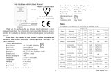
Information on waste disposal for consumers of electrical & electronic equipment.
When this product has reached the end of its life it must be treated as Waste Electrical & Electronics Equipment (WEEE). Any WEEE
marked products must not be mixed with general household waste, but kept separate for the treatment, recovery and recycling of
the materials used. Please contact your supplier or local authority for details of recycling schemes in your area.
At the end of their working life, electrochemical sensors should be disposed of in an environmentally safe manner.
Alternatively, they can be securely packaged and returned to AGS clearly marked for disposal. Electrochemical sensors
should not be incinerated as this may cause the cell to emit toxic fumes.

Installation & Operation Manual Merlin 1000SW+
Rev: 14 08-22 4
Installation
Typical Application & Location
Installation must be carried out by a licenced, insured contractor!
Installation must be in accordance with recognised standards in the country concerned, for North America, NEC / CEC
regulations should be followed!
Cables must be protected against mechanical damage!
The 1000SW+ panel is a gas pressure proving, electric and water isolation system is designed
specifically for use in educational establishments and laboratories.
The panel is designed to give the teacher full control over the incoming gas supply, bench electrics
and water supply with the lockable main key-switch and touch sensors.
The panel can work in conjunction with carbon dioxide, natural gas, carbon monoxide and LPG
sensors. It also has a built in “timeout” facility which will automatically shut off the gas solenoid valve
at the end of a specific time, this time can be adjusted to 2, 5, 8 hours or can be overridden if
required.
Mounting & Cabling
If mounting direct to wall - ensure the wall surface is flat to prevent base distortion!
Ensure the rear base is installed in the correct orientation as shown!
Where cable glands/conduits are used for wire entry, use 20mm (3/4 inch) max separated by at least 20mm!
Any parts that form part of the connections/installation must have a minimum fire-retardant rating of UL94v-2!
Damage to PCBs when creating cable entry points or attempting to remove the circuit board may void any warranty!
Restrain the hazardous live wiring from accidental loosening to prevent wires from moving after installation and touching
parts of opposite polarity or at low voltages!
Isolate the equipment from all hazardous live power sources before opening the cover!
Place the panel 48-60 inches above finished floor level.
Designed for surface mounting, it must be installed by a licensed,
insured contractor.
1. Carefully remove the front cover from the unit by unscrewing the
four bolts located at each corner. To do this – use the socket wrench provided.
2. Remove the keys and spare parts - keep safe.
3. Mark the four screw holes located on the back of the enclosure to the wall. Ensure the wall surface is flat
to prevent base distortion. Drill out as necessary ensuring all swarf is removed from the box and holes
have smooth edges.
4. After executing the mounting and the connections –replace the front cover and insert the security caps
over the four bolts.
A flush mount kit is available, comprising of a mounting bracket and decorative surround strip.
Contact your supplier for more information.

Installation & Operation Manual Merlin 1000SW+
Rev: 14 08-22 5
Circuit Board Connections Overview
POWER / LINE IN
110-120V AC Power should be supplied to the [POWER / LINE IN] terminal and fused at 3A.
GAS SOLENOID VALVE OUTPUT
110-120V AC electrical power supplied from the [VALVE OUT] connector using a 3-core cable can be
connected to a gas solenoid valve which can shut the gas supply on alarm status.
ELECTRIC CONTACTOR OUTPUT
110-120V AC electrical power supplied from the [ELECTRIC CONTACTOR] connector using a 3-core
cable can be connected to a contactor.
WATER VALVE OUTPUT
110-120V AC electrical power supplied from the [WATER VALVE] connector using a 3-core cable can be
connected to a contactor. Refer to your water valve manual for more information and wiring!
BMS OUT
Connections are available on the board for Building Management Systems.
[NO Normally Open] [COM Common] [NC Normally Closed] These are dry contact connections.
This is a relay that changes state in alarm or when the gas is on/off and can be used in conjunction with
the 12V DC output and other external relays that affect other devices and controls such as purge fans
and audible alarms etc. See section; Switch Settings - for BMS options

Installation & Operation Manual Merlin 1000SW+
Rev: 14 08-22 6
PRESSURE SENSOR
The pressure sensor is screwed into the downstream port of the gas solenoid valve.
Connect the pressure sensor: Wiring: Red [+] Black [-] Blue [IN]
The sensor will monitor the gas supply pressure and if pressure drops below 0.17psi – the gas valve will
close as this could mean a gas leak is present. The operating pressure is: 0 – 1.45psi.
EM REMOTE / FIRE PANEL
Connections for remote emergency shut-off buttons or integrated with a fire alarm to close the gas
supply automatically in the event of a fire. This is linked out as a factory setting.
Remote emergency shut-off buttons should be dry contact and wired to the using a plenum security
cable, white, 18/2 (18AWG 2 conductor), stranded, CMP or similar.
WIRING GAS DETECTORS
Refer to your gas detector manual for further information!
If no detector is being used leave the factory fitted link in!
Connecting a Gas Detector i / i-S
Connecting a Gas Detector

Installation & Operation Manual Merlin 1000SW+
Rev: 14 08-22 7
Connecting a Gas Detector TFT
FAN SWITCHES (FS 1 / 2 / 3)
These terminals can be connected to a fan switch (supplied separately) which provide power to fans
when the emergency shut-off button is pressed.
Example of an AGS FS1 given.

Installation & Operation Manual Merlin 1000SW+
Rev: 14 08-22 8
CO2 MONITOR & 12VDC
Primarily this is used to power the AGS CO2-X but can be used as a power output for external auxiliary
devices when there is power at the panel and can be used to create a relay switch with the BMS relay
output. Max output: 50mA. If no CO2 monitor or other device is connected, the panel will ‘beep’ upon
power up and the CO2 LED will flash 3 times to indicate that this terminal has been disabled.
Switch Settings – Auto Reset
OFF
When power is restored after the power cut/ loss, the panel has to be restarted
manually. (Default)
ON
This will instruct the system to restart automatically when power is restored after
power cut/loss.
Switch Settings – BMS Integration
The panel can be integrated with a BMS to make or break a circuit when the gas is either on or off,
(valve open or valve closed). This will tell the BMS whether power is being sent to the solenoid valve.
OFF
Signals the BMS when gas is on or gas is off. (Default)
ON
Signals the BMS on a fault i.e. high gas levels detected, emergency shut-off
activated etc.

Installation & Operation Manual Merlin 1000SW+
Rev: 14 08-22 9
Switch Settings – Gas Fill & Prove Time
Once the settings have been changed - remove power for 10 seconds.
FILL TIME: Amount of time the gas valve opens to fill the gas line on power up or reset.
PROVE TIME: Amount of time the system tests the gas line for leaks on power up or reset.
Fill Time
Prove Time
OFF
5 Seconds (Default)
OFF
30 Seconds (Default)
ON
10 Seconds
ON
50 Seconds
Switch Settings – Automatic Shut Down Timer
The system has an auto-shut down feature after a selected time.
There are two switches located on the circuit board labelled [TIME1] & [TIME2].
These can be configured to select the required timeout/ shut-down period.
TIME 1
TIME 2
Timeout Period
OFF
OFF
2 Hours (Default)
ON
OFF
4 Hours
OFF
ON
8 Hours
ON
ON
Disabled
Upon timeout the gas supply will be turned off unless other utilities are configured.
Switch Settings – Utility Shutdown Selection
There are two switches located on the circuit board labelled [ELECTR] and [WATER].
They are factory set to ‘Off’.
On installation, they can be switched ‘On’. This will instruct the system to also turn off Electric
and/or Water services when performing auto-shut down/ timeout.

Installation & Operation Manual Merlin 1000SW+
Rev: 14 08-22 10
Operation
Initial Power Up
All services can be turned on or off within 10 seconds only of the key switch being turned on. After 10 seconds, all utility
buttons will be disabled. The user must turn the key off and back on to adjust any services.
Turn the key switch to on position. Gas, Electric and Water LEDs will flash for 10 seconds. Press relevant
service button to turn required utility on.
LED Indicators
• Gas
When the key switch is turned on, the system will check the installation for gas leaks.
If gas proving is successful, the LED will illuminate. ON = Gas On / OFF = Gas Off
• Electric
When electric service is turned on, the Electric LED will illuminate.
ON = Electric on / FLASHING = Electric Off, Electric button enabled / OFF = Electric Off, Electric button disabled.
• Water
When water service is turned on, the Water LED will illuminate.
ON = Water on / FLASHING = Water Off, Water button enabled / OFF = Water Off, Water button disabled.
• Testing
This LED will illuminate GREEN for approximately 30 seconds when the panel is checking the integrity of
the gas installation upon start up. ON = proving the gas line, do NOT operate any appliances.
• Test Fail
Under normal working conditions this LED is off. When the panel detects a gas leak on start-up, the LED
will illuminate AMBER. Gas valve will remain closed. OFF = OK / ON = gas proving failed.
• Pressure Low
Under normal working conditions the LED is off. The LED will illuminate AMBER when pressure of the
gas supply drops below 0.17psi for 10 secs. The gas valve will close. OFF = OK / ON = gas supply pressure low.
• Timeout
Under normal working conditions this LED is off. This LED will illuminate AMBER when auto-shut down
has occurred. OFF = OK / ON = Auto-shut down activated
• EM Stop
If an emergency shut off button (either remote or on the panel) is pressed, the LED will illuminate
AMBER and the gas will be turned off and the fans switch (if a fan switch is connected). The EM Stop
button must be reset before restarting the system. The emergency shut off button(s) will cut off the gas
supply, electrics, and fans (if connected) when activated. OFF = OK / ON = Emergency Shut-Off button activated.
• CO2/ Gas Detected
Under normal working conditions this LED is off. If the external Merlin detector connected detects gas
this will show RED, and the gas valve will turn off. OFF = OK / ON = Gas detected.
• CO2 High
Under normal working conditions this LED is off.
If the concentration of CO2 in the air is at alarm level (relevant detector required), the LED will show
RED, and the gas valve will close. OFF = OK / ON = the concentration of CO2 is at alarm level.

Installation & Operation Manual Merlin 1000SW+
Rev: 14 08-22 11
Maintenance
Cleaning
Concentrations of alcohol found in many products may damage, deteriorate, or affect the gas sensing elements such as
wine; deodorants; stain removers and thinners. Other gases and substances to avoid are corrosives (i.e., chlorine &
hydrogen chloride); alkali metals; basic or acidic compounds; silicones; tetraethyl lead; halogens and halogenated
compounds!
Keep your panel in good working order - follow these basic principles.
• Remove any dust/debris from the outer enclosure regularly using a slightly damp cloth.
• Never use detergents or solvents to clean your device.
• Never spray air fresheners, hair spray, paint or other aerosols near the device.
• Never paint the device. Paint will seal vents and interfere with the device.
Bump Testing (Gas Response Check)
All certified test gases supplied by AGS are classified as non-flammable and non-toxic, however, they may contain gas
under pressure and may explode if heated to extreme temperatures and cause asphyxiation in high concentrations.
Always use in accordance with the safety data sheet!
Gas response checks are often referred to as a ‘bump test’. Bump tests are important to make sure a
device can detect a release of gas as early as possible. The aim of the bump test is to make sure a
detector is working at its optimum by briefly exposing the unit to a known concentration of the target gas
that usually exceeds the highest alarm point. If the detector goes into alarm and all signals/outputs
activate, then the system is working.
If the system fails to operate as intended in an alarm state, the gas detector must not be used until a full
inspection and service has been conducted. NFPA requires all gas detectors to be tested annually and
that the test results be recorded on site and available to inspectors.
A detector may visually appear in good working order, but its sensitivity and accuracy can be inhibited
by external factors. Dust, humidity, temperature fluctuations, cleaning products, contaminants, exposure
to its target gas or sensor drift (ageing) can cause a decline in sensitivity, accuracy, and eventual failure.
Regular bump tests are important to make sure the detector can detect a release of gas as early as
possible and usually takes seconds (gas type dependant i.e., CO sensors will take over a minute) and is
often completed alongside a scheduled fire alarm test, however the frequency should be determined
following an appropriate risk assessment by the end user.
We recommend testing detectors every 12-18 months along with the regular fire test procedures and
coincide with the annual service message prompted on the detection system after each year of
service/operation.
Contact your AGS representative for details of suitable bump testing kits and gases. Kits usually consist
of a certified gas cylinder or spray. We recommend only using AGS calibration gas kits to ensure correct
flow rates meet AGS technical requirements. A bump testing gas is usually a concentration mix that
exceeds the highest alarm set point.

Installation & Operation Manual Merlin 1000SW+
Rev: 14 08-22 12
Specification
General
Model:
1000SW+
Size: (H x W x D)
7.08 x 10.03 x 3” (180 x 255 x 77 mm)
Housing Material:
ABS Polylac - PA765. UL 94 V-1
Mounting:
Indoor use - Wall Mounting
User Interface
Visual Indicators:
LED
Audible Alarm:
>70dB @ 3.28ft (1m). Quiet conditions.
Language:
English
Power Supply
Power Rating:
6W max.
Voltage Rating:
100-120V~ 50-60Hz
Internal Fuse:
T3.15A L250V
Equipment
Overvoltage Category:
II
Pollution Degree:
2
Equipment Class:
2
Environmental
Ingress Protection:
Not Formally Evaluated
Operating:
-10 ~ 50°C / 14 ~ 122°F 30 ~ 80% RH (non-condensing)
Storage:
-25 ~ 50°C / -13~122F° up to 95% RH (non-condensing)
Altitude Rating:
2000m
Approvals
Electromagnetic Compatibility and
Electrical Safety
IEC 61010-1:2010 + AMD1:2016; EN 61010-1:2010 +A1:2019; UL61010-1/2012/R:2019-07;
CAN CSA C22.2 No. 61010-1-12/A1:2018-11
EMC EN 61326-1:2013
UL Approval Reference
E464760
Installation Details
Please pass this manual to the system owner or system user.
Date of Installation:
Installation Location:
Organisation:
Stamp/ Signature of the installer:
Every effort is made to ensure the accuracy of this document; however, AGS can assume no responsibility for any errors or
omissions in this document or their consequences. AGS would greatly appreciate being informed of any errors or omissions that
may be found in the content of this document. For information not covered in this document, or if there is a requirement to send
comments/corrections, please contact AGS using the contact details.
American Gas Safety LLC
Head office:
6304 Benjamin Road, Suite 502, Tampa, FL 33634
Tel: (727) 608-4375
American Gas Safety LLC is the owner of this document and reserves all rights of modification without prior notice.
/