Schneider Electric ATV630U55N4 Operating instructions
- Type
- Operating instructions

1/8
E6581354-04
02/2019
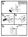
Altivar Flange Mounting Kit
Electrical equipment should be installed, operated, serviced, and maintained only by qualified personnel. No responsibility
is assumed by Schneider Electric for any consequences arising out of the use of this product.
© 2019 Schneider Electric. All Rights Reserved.
DANGER
HAZARD OF ELECTRIC SHOCK, EXPLOSION, OR ARC FLASH
• Only appropriately trained persons who are familiar with and understand the contents of this manual and all other
pertinent product documentation and who have received safety training to recognize and avoid hazards involved are
authorized to work on and with this drive system. Installation, adjustment, repair, and maintenance must be
performed by qualified personnel.
• The system integrator is responsible for compliance with all local and national electrical code requirements as well
as all other applicable regulations with respect to grounding of all equipment.
• Many components of the product, including the printed circuit boards, operate with mains voltage. Do not touch. Use
only electrically insulated tools.
• Do not touch unshielded components or terminals with voltage present.
• Motors can generate voltage when the shaft is rotated. Prior to performing any type of work on the drive system, block
the motor shaft to prevent rotation.
• AC voltage can couple voltage to unused conductors in the motor cable. Insulate both ends of unused conductors of
the motor cable.
• Do not short across the DC bus terminals or the DC bus capacitors or the braking resistor terminals.
• Before performing work on the drive system:
- Disconnect all power, including external control power that may be present.
- Place a "Do Not Turn On" label on all power switches.
- Lock all power switches in the open position.
- Wait 15 minutes to allow the DC bus capacitors to discharge. The DC bus LED is not an indicator of the
absence of DC bus voltage that can exceed 800 Vdc.
- Measure the voltage on the DC bus between the DC bus terminals (PA/+ and PC/-) using a properly rated
voltmeter to verify that the voltage is <42 Vdc.
- If the DC bus capacitors do not discharge properly, contact your local Schneider Electric representative. Do
not repair or operate the product.
• Install and close all covers before applying voltage.
Failure to follow these instructions will result in death or serious injury.
VW3A9510...VW3A9515
VW3A9510 VW3A9512...515
VW3A9511
Lorem ipsum
E658135404

E6581354-04 www.schneider-electric.com2/8
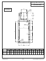
Cut and holes
Flange Mounting Kit
VW3A9510
VW3A9511
VW3A9510
a
in mm
260
310
10.23
12.20
VW3A9511
c
d
e
a f
195
4xØ8
8xØ8
6xØ10
7.67
g
aih
b
b
in mm
790
845
31.10
33.26
c
in mm
340
360
13.38
14.17
d
in mm
150
160
5.90
6.29
e
in mm
15
18
0.59
0.70
f
in mm
100
83.5
3.93
3.28
g
in mm
15
10
0.59
0.39
h
in mm
120
70
4.72
2.75
i
in mm
80
91.5
3.14
3.60

E6581354-04 www.schneider-electric.com3/8
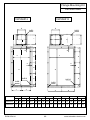
Cut and holes
Flange Mounting Kit
VW3A9512 VW3A9513
VW3A9512
a
in mm
280
280
11.02
11.02
VW3A9513
b
in mm
970
970
38.18
38.18
c
in mm
360
460
14.17
18.11
d
in mm
160
150
6.29
5.90
e
in mm
15
15
0.59
0.59
f
in mm
120
120
4.72
4.72
g
in mm
20
20
0.78
0.78
h
in mm
60
60
2.36
2.36
i
in mm
195
195
7.67
7.67
a f
b
b
g
i
i
aah
a faah
c
e
g
c
e
d d
4xØ8 8xØ8
8xØ10
6xØ8
8xØ10
6xØ8

E6581354-04 www.schneider-electric.com4/8
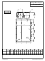
Cut and holes
Flange Mounting Kit
VW3A9514
VW3A9515
VW3A9514
a
in mm
280
280
11.02
11.02
VW3A9515
b
in mm
970
970
38.18
38.18
c
in mm
610
685
24.01
26.96
d
in mm
160
160
6.29
6.29
e
in mm
17.5
17.5
0.68
0.68
f
in mm
120
120
4.72
4.72
g
in mm
20
20
0.78
0.78
h
in mm
60
60
2.36
2.36
i
in mm
215
240
8.46
9.44
a f
g
a
b
ah
c
iii
e
d
195
7.67
8xØ8
8xØ10
8xØ8

E6581354-04 www.schneider-electric.com5/8
1
2 3
4
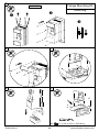
VW3A9510
Mounting
Flange Mounting Kit
M4 1.1...1.7 N·m (9.74...15.05 lbf.in)
M6 4.2...5.1 N·m (37.17...45.14 lbf.in)

E6581354-04 www.schneider-electric.com6/8
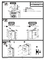
5
6 7
89
Mounting
Flange Mounting Kit
M5 2.6...3.3 N·m (23.01...29.21 lbf.in)
VW3A9510

E6581354-04 www.schneider-electric.com7/8
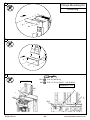
2
1
Mounting
Flange Mounting Kit
VW3A9512...515VW3A9511
VW3A9511...515
M8 13.5 N·m (119.5 lbf.in)M6 4.2...5.1 N·m (37.17...45.14 lbf.in)
VW3A9510
10
M12 41 N·m (360 lbf.in)
M12
M8
M8 10.0...13.5 N·m (88.51...119.49 lbf.in)

E6581354-04 www.schneider-electric.com8/8
3
4
Mounting
Flange Mounting Kit
5
M12 M8
VW3A9511
M12
M8
VW3A9512...515
M12 41 N·m (360 lbf.in)
M8 10.0...13.5 N·m (88.51...119.49 lbf.in)
-
 1
1
-
 2
2
-
 3
3
-
 4
4
-
 5
5
-
 6
6
-
 7
7
-
 8
8


Schneider Electric ATV630U55N4 Operating instructions
- Type
- Operating instructions
Ask a question and I''ll find the answer in the document
Finding information in a document is now easier with AI
Related papers
-
Schneider Electric VW3A3600 Operating instructions
-
Schneider Electric ATV320U22M3C Operating instructions
-
Schneider Electric ZBY9120 Operating instructions
-
-
-
-
-
-
Schneider Electric ATV312 Installation guide
-
Other documents
-
Schneider VW3A3600 User manual
-
Eurotherm ATS22 User manual
-
-
-
-
Danfoss scroll MLM MLZ series - GB - US User guide
-
APC NetShelter SX 42U Specification
-
Square D SC3042M225PF Installation guide
-
Schneider SpaceLogic Thermostat Installation guide