Page is loading ...

Operating Manual
Rough Terrain Compact Series (ANSI/CSA)
MODELS SJ 6826RT SJ 6832RT
129951AF-A September 2010

Skyjack Service Center 3451 Swenson Ave. St. Charles, Illinois, 60174 USA
Phone: 630-262-0005
Toll Free: 1-800-275-9522
Fax: 630-262-0006
Email: [email protected]om
Parts (North America)
Toll Free: 1-800-965-4626
Toll Free Fax: 1-888-782-4825
Email: [email protected]
Parts & Service (Europe) Unit 1 Maes Y Clawdd, Maesbury Road Industrial Estate
Oswestry, Shropshire SY10 8NN UK
Phone: +44-1691-676-235
Fax: +44-1691-676-238
Email: info@skyjackeurope.co.uk
Skyjack Asia Pacic
Singapore
Phone: +65-6449-3710
Fax: +65-6449-7690
Email: [email protected]

SJRT Compact Series
Engine Powered December 2007 Page 3
TM
The Safety Alert Symbol identifies important
safety messages on aerial platform, safety signs
in manuals or elsewhere. When you see this
symbol, be alert to the possibility of personal
injury or death. Follow the instructions in the
safety message.
This Safety Alert Symbol means attention!
Become alert! Your safety is involved.
DANGER indicates an imminently hazardous situation which, if not avoided,
will result in death or serious injury.
WARNING indicates a potentially hazardous situation which, if not avoided,
could result in death or serious injury.
CAUTION indicates a potentially hazardous situation which, if not avoided,
may result in minor or moderate injury. It may also be used to alert against
unsafe practices.
IMPORTANT indicates a procedure essential for safe operation and which,
if not followed, may result in a malfunction or damage to the aerial platform.

TM
Page 4 December 2007
SJRT Compact Series
Engine Powered
Table of Contents
Section 1 - About Your Aerial Platform
Read and Heed
Aerial Platform Definition ..............................................................................................................................................7
Purpose of Equipment .................................................................................................................................................7
Use of Equipment ........................................................................................................................................................7
Manual ..........................................................................................................................................................................7
Operator .......................................................................................................................................................................7
Service Policy and Warranty ........................................................................................................................................7
Optional Accessories ...................................................................................................................................................7
Scope of this Manual ...................................................................................................................................................7
Safety Rules
Operator Safety Reminders .........................................................................................................................................8
Electrocution Hazard ...................................................................................................................................................9
Safety Precautions .....................................................................................................................................................10
Section 2 - Operation
2.1 General ............................................................................................................................................................13
2.1-1 Operator Qualifications .....................................................................................................................13
2.1-2 Operator’s Responsibility for Maintenance ......................................................................................13
2.1-3 Maintenance and Inspection Schedule ............................................................................................13
2.1-4 Owner’s Inspections .........................................................................................................................13
2.2 Major Components .........................................................................................................................................14
2.3 Major Assemblies ...........................................................................................................................................15
2.3-1 Base .................................................................................................................................................15
2.3-2 Lifting Mechanism .............................................................................................................................15
2.3-3 Platform .............................................................................................................................................15
2.4 Serial Number Nameplate ..............................................................................................................................15
2.5 Component Identification ...............................................................................................................................16
2.5-1 Main Power Disconnect Switch ........................................................................................................16
2.5-2 Motion Alarm .....................................................................................................................................16
2.5-3 Tilt Alarm ...........................................................................................................................................16
2.5-4 Brake System ....................................................................................................................................16
2.5-5 Emergency Lowering System ...........................................................................................................17
2.5-6 Free-wheeling Valve ..........................................................................................................................17
2.5-7 Propane Cylinder ..............................................................................................................................17
2.5-8 Base Control Console .......................................................................................................................18
2.5-9 Maintenance Support .......................................................................................................................19
2.5-10 Manual Storage Box .........................................................................................................................19
2.5-11 Platform Control Console .................................................................................................................20
2.5-12 Folding Guardrail System .................................................................................................................21
2.5-13 Safety Belt/Harness Attachment Bar ................................................................................................21
2.6 Component Identification (Special Options) ...................................................................................................22
2.6-1 Outrigger/Generator Control Console (If Equipped) ........................................................................22
2.6-2 800W AC Inverter (If Equipped) ........................................................................................................22
2.6-3 Tire Sealant (If Equipped) .................................................................................................................23
2.7 Operator’s Responsibility ................................................................................................................................24
2.8 Visual and Daily Maintenance Inspections .....................................................................................................25
2.9 Function Tests..................................................................................................................................................34

SJRT Compact Series
Engine Powered December 2007 Page 5
TM
Table of Contents
Section 2 - Operation (Continued)
2.10 Start Operation ................................................................................................................................................41
2.10-1 To Activate Base Control Console ....................................................................................................42
2.10-2 To Raise or Lower Platform Using Base Control Console ................................................................42
2.10-3 To Activate Platform Control Console ...............................................................................................43
2.10-4 To Raise or Lower Platform Using Platform Control Console ..........................................................43
2.10-5 To Drive Forward or Backward .........................................................................................................44
2.10-6 To Steer .............................................................................................................................................44
2.10-7 To Select Drive Torque ......................................................................................................................45
2.10-8 To Extend or Retract Manual Extension Platform .............................................................................45
2.10-9 Hydraulic Outriggers (If Equipped) ..................................................................................................46
2.10-10 Generator (If Equipped) ....................................................................................................................47
2.10-11 Electrical Inverter (If Equipped) ........................................................................................................47
2.10-12 Shutdown Procedure ........................................................................................................................47
2.11 Refueling Procedure ........................................................................................................................................48
2.11-1 Regular Fuel ......................................................................................................................................48
2.11-2 Propane .............................................................................................................................................49
2.12 Loading/Unloading ..........................................................................................................................................50
2.12-1 Lifting .................................................................................................................................................50
2.12-2 Driving ...............................................................................................................................................51
2.13 Guardrail Folding Procedure ...........................................................................................................................52
2.14 Moving the Aerial Platform Through a Doorway .............................................................................................54
2.15 Winching and Towing Procedure ....................................................................................................................56
2.15-1 To Release Free-wheeling Valve .......................................................................................................56
2.15-2 To Release Brakes Manually .............................................................................................................57
2.16 Emergency Lowering Procedure ....................................................................................................................58
2.17 Maintenance Support Procedure ....................................................................................................................59
2.18 Tables...............................................................................................................................................................60
2.19 Labels ..............................................................................................................................................................68
List of Tables
Table 2.1 Standard and Optional Features .............................................................................................................60
Table 2.2 Specifications and Features.....................................................................................................................61
Table 2.3 Owner’s Annual Inspection Record .........................................................................................................62
Table 2.4 Maximum Platform Capacities (Evenly Distributed) ...............................................................................63
Table 2.5 Floor Loading Pressure ............................................................................................................................64
Table 2.6 Maintenance and Inspection Schedule ...................................................................................................66
Table 2.7 Operator’s Checklist ................................................................................................................................67

SJRT Compact Series
Engine Powered December 2007 Page 7
TM
Section 1 - About Your Aerial Platform Read and Heed
SKYJACK is continuously improving and expanding product features on its equipment, therefore, specifications
and dimensions are subject to change without notice.
Aerial Platform Definition
A mobile device that has an adjustable position platform supported from ground level by a structure.
Purpose of Equipment
The SKYJACK Rough Terrain Compact Series aerial platform is designed to transport and raise personnel, tools
and materials to overhead work areas.
Use of Equipment
The aerial platform is a highly maneuverable, mobile work station. Lifting and driving must be on a flat, level,
compacted surface. It can be driven over uneven terrain only when the platform is fully lowered.
Manual
The operating manual is considered a fundamental part of the aerial platform. It is a very important way to
communicate necessary safety information to users and operators. A complete and legible copy of this manual
must be kept in the provided weather-resistant storage compartment on the aerial platform at all times.
Operator
The operator must read and completely understand both this operating manual and the safety panel label located on
the platform and all other warnings in this manual and on the aerial platform. Compare the labels on the aerial platform
with the labels found within this manual. If any labels are damaged or missing, replace them immediately.
Service Policy and Warranty
SKYJACK warrants each new SJRT Compact Series work platform to be free of defective parts and workmanship
for the first 24 months. Any defective part will be replaced or repaired by your local SKYJACK dealer at no charge
for parts or labor. Contact the SKYJACK Service Department for warranty statement extensions or exclusions.
Optional Accessories
The SKYJACK aerial platform is designed to accept a variety of optional accessories. These are listed under
“Standard and Optional Features” in Table 2.1. Operating instructions for these options (if equipped) are located
in Section 2 of this manual.
For non-standard components or systems, contact the SKYJACK Service Department at
( : 800 275-9522
7 : 630 262-0006
Include the model and serial number for each applicable aerial platform.
Scope of this Manual
a. This manual applies to the ANSI/SIA, CSA version of the SJRT Compact Series aerial platform models listed
on Table 2.1.
- Equipment identified with “ANSI” meets the ANSI SIA-A92.6-2006 standard.
- Equipment identified with “CSA” meets the CSA B354.2-01 standard.
b. CSA (Canada)
Operators are required to conform to national, territorial/provincial and local health and safety regulations
applicable to the operation of this aerial platform.
c. ANSI/SIA (United States)
Operators are required by the current ANSI/SIA A92.6 standards to read and understand their responsibilities
in the manual of responsibilities before they use or operate this aerial platform.
1

TM
Page 8 December 2007
SJRT Compact Series
Engine Powered
Safety Rules Section 1 - About Your Aerial Platform
Failure to comply with your required responsibilities in the use and operation of the aerial platform
could result in death or serious injury!
Operator Safety Reminders
A study conducted by St. Paul Travelers showed that most accidents are caused by the failure of the operator to
follow simple and fundamental safety rules and precautions.
You, as a careful operator, are the best insurance against an accident. Therefore, proper usage of this aerial
platform is mandatory. The following pages of this manual should be read and understood completely before
operating the aerial platform.
Common sense dictates the use of protective clothing when working on or near machinery. Use appropriate safety
devices to protect your eyes, ears, hands, feet and body.
Any modifications from the original design are strictly forbidden without written permission from SKYJACK.

SJRT Compact Series
Engine Powered December 2007 Page 9
TM
Section 1 - About Your Aerial Platform Safety Rules
Electrocution Hazard
This aerial platform is not electrically insulated. Maintain a Minimum Safe Approach Distance (MSAD) from energized
power lines and parts as listed below. The operator must allow for the platform to sway, rock or sag. This aerial
platform does not provide protection from contact with or proximity to an electrically charged conductor.
Per ANSI A92.6-2006 8.10(7)
“The operator shall perform only that work for which he or she is qualified, in compliance with all applicable
safety related work practices intended to prevent electric shock covered by the Code of Federal Regulations
(CFR) 1910.333. The operator’s level of competence shall be established only by persons qualified to do so.
Operators shall maintain the appropriate minimum approach distance (MAD) from energized power lines and parts
covered by CFR 1910.333 (c).”
Unqualified persons must maintain a minimum approach distance of 10 feet from any energized power line up to
50 kV. Energized power lines over 50 kV require a greater minimum approach distance to be maintained. Refer to
CFR 1910.333.
As per CSA B354.2-01
“The operator shall maintain the minimum safe approach distance (MSAD) from energized conductors at all times
in accordance with the authority having jurisdiction.”
As per AS 2550.1-2002
Elevating Work Platforms must remain 6.4 m from electrical distribution lines up to 133 kV and 8 m from transmission
lines greater than 133 kV. State regulations may take precedence over these approach distances.
DO NOT USE THE AERIAL PLATFORM AS A GROUND FOR WELDING.
DO NOT OPERATE THE AERIAL PLATFORM DURING LIGHTNING OR STORMS.
Voltage Range Minimum Safe Approach Distance
(Phase to Phase) (Feet)
0 to 300V Avoid Contact
Over 300V to 50KV 10
Over 50KV to 200KV 15
Over 200KV to 350KV 20
Over 350KV to 500KV 25
Over 500KV to 750KV 35
Over 750KV to 1000KV 45
60023AD-ANSI
DANGER
FAILURE TO AVOID THIS HAZARD WILL RESULT IN DEATH OR SERIOUS INJURY!
Avoid Power Lines
Minimum Safe Approach Distance
ANSI/SIA A92.6-2006 & CSA B354.2-01 Requirements

TM
Page 10 December 2007
SJRT Compact Series
Engine Powered
Safety Rules Section 1 - About Your Aerial Platform
Safety Precautions
Know and understand the safety precautions before going on to next section.
Failure to heed the following safety
precautions could result in tip over,
falling, crushing, or other hazards
leading to death or serious injury.
• all national, state/provincial and local
rules which apply to your aerial platform and
jobsite.
• emergency main power disconnect
switch “ ” off when leaving the aerial platform
unattended. Remove the key to prevent
unauthorized use of the aerial platform.
• all the protective clothing and personal
safety devices issued to you or called for by job
conditions.
• wear loose clothing,
dangling neckties, scarves,
rings, wristwatches or other
jewelry while operating this
aerial platform.
• entanglement with
ropes, cords or hoses.
• falling. Stay within the
boundaries of the guardrails.
• raise the aerial
platform in windy or gusty
conditions.
• increase the lateral
surface area of the platform.
Increasing the area exposed
to the wind will decrease aerial
platform stability.
• drive or elevate the
aerial platform if it is not on a
firm level surface. Do not drive
elevated near depressions
or holes of any type, loading
docks, debris, drop-offs and
surfaces that may affect the
stability of the aerial platform.
•
,
elevated driving shall not be
allowed. Position the aerial
platform horizontally only with
the platform fully lowered. After
ensuring that all 4 wheels or
outriggers (if equipped) have
contact with level firm surface,
the aerial platform can be
elevated. After elevation, the
drive function must not be
activated.
• must
only be done on a firm level
surface.
• ascend or descend
a grade when elevated. When
fully lowered, ascending or
descending, only grades up
to rated maximum listed in
Table 2-2 are permissible.

SJRT Compact Series
Engine Powered December 2007 Page 11
TM
Section 1 - About Your Aerial Platform Safety Rules
Safety Precautions (Continued)
Know and understand the safety precautions before going on to next section.
• operate on surfaces not capable of
holding the weight of the aerial platform including
the rated load, e.g. covers, drains, and trenches.
• operate an aerial
platform that has ladders,
scaffolding or other devices
mounted on it to increase
its size or work height. It is
prohibited.
• exert side forces on
aerial platform while elevated.
• use the aerial platform
as a crane. It is prohibited.
• sit, stand or climb on
the guardrails. It is prohibited.
• climb on scissor arm
assembly. It is prohibited.
• of overhead
obstructions or other possible
hazards around the aerial
platform when driving or lifting.
• raise the aerial platform
while the aerial platform is on a
truck, fork lift or other device or
vehicle.
• of crushing
hazards. Keep all body parts
inside platform guardrail.
• lower the platform
unless the area below is
clear of personnel and
obstructions.
• that there are no personnel or
obstructions in the path of travel, including blind
spots.
• of blind spots when operating the
aerial platform.
• driving and horseplay are prohibited.
• tires are in good condition and lug
nuts are properly tightened.
• alter or disable limit switches or other
safety devices.
• use the aerial platform without
guardrails, locking pins and the entry gate/chain/
bar in place.

TM
Page 12 December 2007
SJRT Compact Series
Engine Powered
Safety Rules Section 1 - About Your Aerial Platform
Safety Precautions (Continued)
Know and understand the safety precautions before going on to next section.
• exceed the rated capacity of the
aerial platform. Do make sure the load is evenly
distributed on the platform.
• attempt to free a snagged platform with
lower controls until personnel are removed from
the platform.
• position the aerial platform against
another object to steady the platform.
• place materials on the guardrails
or materials that exceed the confines of the
guardrails unless approved by Skyjack.
Fall Protection
As per the ANSI A92.6-2006 standard, “The
guardrail system of the aerial platform provides
fall protection. If occupant(s) of the platform are
required to wear personal fall protection equipment
(PFPE), occupants shall comply with instructions
provided by the aerial platform manufacturer
(remanufacturer) regarding anchorage(s).”
If additional fall protection is required, by an
employer or the authority having jurisdiction,
Skyjack recommends the use of a fall restraint
system to keep an occupant within the confines
of the platform, and thus not expose the occupant
to any fall hazard requiring a fall arrest.
All personal fall protection equipment must
comply with applicable governmental regulations
and must be inspected and used in accordance
with the manufacturer’s recommendations.
All personal fall protection equipment must be
attached only to approved anchorage points
within the platform of the aerial platform.
Entering and exiting the aerial platform
should only be done using the three
points of contact.
Use only equipped access openings• .
Enter and exit only when the aerial •
platform is in the fully retracted position.
• Do use three points of contact to enter and exit
the platform. Enter and exit the platform from
the ground only. Face the aerial platform when
entering or exiting the platform.
• Three points of contact means that two hands and
one foot or one hand and two feet are in contact
with the aerial platform or the ground at all times
during entering and exiting.
An operator should not use any aerial
platform that:
does not appear to be working properly.•
has been damaged or appears to have worn or •
missing parts.
has alterations or modifications not approved by •
the manufacturer.
has safety devices which have been altered or •
disabled.
has been tagged or blocked out for non-use or •
repair.
Failure to avoid these hazards could
result in death or serious injury.
Jobsite Inspection
Do not use in hazardous locations.•
Perform a thorough jobsite inspection prior to •
operating the aerial platform, to identify potential
hazards in your work area.
Be aware of moving equipment in the area. Take •
appropriate actions to avoid collision.

SJRT Compact Series
Engine Powered December 2007 Page 13
TM
Section 2 - Operation
2.0 Operation
This section provides the necessary information needed
to operate the aerial platform. It is important that the user
reads and understands this section before operating
the aerial platform.
2.1 General
In order for this aerial platform to be in good working
condition, it is important that the operator meets the
necessary qualifications and follow the maintenance
and inspection schedule referred to in this section.
2.1-1 Operator Qualifications
Only trained and authorized personnel shall• be
permitted to operate an aerial platform.
Safe use of this aerial platform requires the •
operator to understand the limitations and
warnings, operating procedures and operator’s
responsibility for maintenance. Accordingly, the
operator must understand and be familiar with this
operating manual, its warnings and instructions,
and all warnings and instructions on the aerial
platform.
The operator must be familiar with employer’s work •
rules and related government regulations and be
able to demonstrate the ability to understand and
operate this make and model of aerial platform in
the presence of a qualified person.
2.1-2 Operator’s Responsibility for
Maintenance
Maintenance must be performed by
trained and competent personnel who are
familiar with mechanical procedures.
Death or serious injury could result from
the use of an aerial platform that is not
properly maintained or kept in good
working condition.
The operator must be sure that the aerial platform •
has been properly maintained and inspected
before using it.
The operator must perform all the daily inspections •
and function tests found in Table 2.6, even if
the operator is not directly responsible for the
maintenance of this aerial platform.
2.1-3 Maintenance and Inspection Schedule
The inspection points covered in • Table 2.6 indicate
the areas of the aerial platform to be maintained or
inspected and at what intervals the maintenance
and inspections are to be performed.
The actual operating environment of the aerial •
platform may affect the maintenance schedule.
Use original or manufacturer-approved
parts and components for the aerial
platform.
2.1-4 Owner’s Inspections
It is the responsibility of the owner to arrange daily,
quarterly (or 150 hours) and annual inspections of the
aerial platform. Refer to Table 2.6 for recommended
maintenance and inspection areas and intervals. A
record of annual inspection is kept on a label located
on the scissor assembly. Refer to Table 2.3 in this
manual.
2

TM
Page 14 December 2007
SJRT Compact Series
Engine Powered
Major Components Section 2 - Operation
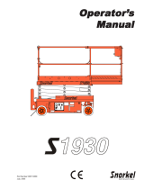
2.2 Major Components
Entry Gate
Platform Control Console
Main
Platform
Lifting
Mechanism
Engine
Compartment
Manual Storage
Box
Extension
Platform
Base
Outriggers
SKYJACK Model SJ 6826RT Aerial Platform
Propane Tank
Maintenance
Support

SJRT Compact Series
Engine Powered December 2007 Page 15
TM
Section 2 - Operation Major Assemblies
2.3 Major Assemblies
The aerial platform consists of three major assemblies:
base, lifting mechanism and platform.
2.3-1 Base
The base is a rigid, one-piece weldment which supports
two side compartments.
One compartment contains the engine, 12V •
battery, base control console and electrical
components. The other compartment contains
the emergency lowering system, brake release
and hydraulic components as well as fuel and
hydraulic tanks.
The propane cylinders (if equipped) are located on •
both sides of the hydraulic/fuel compartment.
The four wheels are hydraulically-motor driven •
with two front wheels steerable by a hydraulic
cylinder.
The rear wheel motors have spring-applied •
hydraulically released disc brakes.
2.3-2 Lifting Mechanism
The lifting mechanism is constructed of formed steel or
tube sections making up a scissor-type assembly. The
scissor assembly is raised and lowered by single-acting
hydraulic lift cylinders with holding valves. A two-section
pump, driven by an engine, provides hydraulic power
to the lift cylinders.
2.3-3 Platform
The platform is constructed of a tubular support frame,
a skid-resistant “diamond plate” deck surface and 39”
hinged guardrails with 6” toe boards and mid-rails. The
platform can be entered from the rear through a spring
returned gate with latch. The platform is also equipped
with a manual extension platform. A 110V outlet is also
located on the platform.
2.4 Serial Number Nameplate
The serial number nameplate, located at the rear of the
aerial platform, lists the following:
Model number•
Serial number•
Aerial platform weight•
Maximum drivable height•
Maximum capacities•
Maximum number of persons permissible on •
the platform
Voltage•
System pressure•
Lift pressure•
Maximum platform height•
Maximum wheel load•

TM
Page 16 December 2007
SJRT Compact Series
Engine Powered
Component Identification Section 2 - Operation
2.5 Component Identification
The following descriptions are for identification,
explanation and locating purposes only.
2.5-1 Emergency Main Power Disconnect
Switch
This switch is located at the left side of the engine
compartment.
1
Figure 2-1. Emergency Main Power Disconnect Switch
1. Emergency Main Power Disconnect Switch -
This switch, when in “ ” off position, disconnects
power to all circuits. Switch must be in “ ” on
position to operate any circuit. Turn switch “ ” off
when transporting aerial platform.
2.5-2 Motion Alarm
The alarm produces an audible sound when any control
function is selected. On aerial platforms with certain
options, a flashing amber light will accompany this
alarm.
2.5-3 Tilt Alarm
The aerial platform is equipped with a device which
senses when the aerial platform is out of level in any
direction. When activated, it disables drive and lift
functions of the aerial platform and an alarm produces
an audible sound accompanied by the amber light. If
the alarm sounds, lower the platform completely, then
reposition aerial platform so that it is level before raising
the platform.
If the tilt alarm sounds and the platform does
not, or only partially raises, immediately
lower the platform completely and ensure
that the aerial platform is on a firm level
surface.
2.5-4 Brake System
The brake system is located on the main manifold in
the hydraulic/fuel compartment. The brakes must be
manually disengaged before pushing, winching or
towing. Refer to Section 2.15-2 for procedure on how
to release the brakes manually. The system contains
the following controls:
2
1
Figure 2-2. Brake System
1. Brake hand pump
2. Brake auto reset valve plunger

SJRT Compact Series
Engine Powered December 2007 Page 17
TM
Section 2 - Operation Component Identification
2.5-5 Emergency Lowering System
The emergency lowering system allows platform
lowering in the event of an emergency or an electrical
system failure. Refer to Section 2.16 for the emergency
lowering procedure. The system contains the following
controls:
1
3
2
Figure 2-3. Emergency Lowering System
Holding Valve Manual Override Knob1. - Located
on the holding valve at the bottom of each lift
cylinder.
Emergency Lowering Valve2. - Located at the
hydraulic/fuel compartment.
Emergency Lowering Access Rod3. - Located at
the right side of the base.
2.5-6 Free-wheeling Valve
1
Figure 2-4. Free-wheeling Valve
Free-wheeling Valve1. - The free-wheeling valve
is located on the main manifold in the hydraulic/
fuel compartment. Refer to Section 2.15-1 for
procedure on how to release the free-wheeling
valve.
2.5-7 Propane Cylinder
The propane cylinder is located on the base of the aerial
platform. It has the following control:
11
Figure 2-5. Propane Cylinder
1. Cylinder Main Valve - Turn this valve clockwise to
shut off the fuel supply; counterclockwise to open
it.

TM
Page 18 December 2007
SJRT Compact Series
Engine Powered
Component Identification Section 2 - Operation
2.5-8 Base Control Console
The control console is located on the left side of
the engine compartment. It contains the following
controls:
5
1
2
3
48
9
7
6
Figure 2-6. Base Control Console - Dual Fuel
5
1
2
3
48
9
7
6
Figure 2-7. Base Control Console - Diesel
Hourmeter 1. - This gauge records accumulated
operating time of engine.
Circuit Breakers 2. - In the event of a power overload
or positive circuit grounding, the circuit breaker
pops out. Push breaker back in to reset.
Choke Pushbutton3. (Dual Fuel) - This pushbutton
switch aids in starting a cold dual-fuel engine.
Glow Plug Pushbutton (Diesel) - This pushbutton
switch energizes the glow plugs to aid in starting
a cold diesel engine.
4. Engine Start Pushbutton - This pushbutton “ ”
energizes the engine starter motor.
5. Platform Raise/Lower Switch - This switch
controls “ ” raising or “ ” lowering of
platform.
6. Emergency Stop Button - This button “ ”, when
depressed, disconnects power to control circuit
and shuts engine off.
7. Power Indicator Light - When the emergency
stop button on the base control console and on
the platform control console are both pulled out,
this light glows.
8. Fuel Switch (Dual Fuel) - Used to switch between
“ ” liquid propane gas and “ ” gasoline.
Glow Plug Indicator Light (Diesel) - This red
lamp “ ” illuminates until the glow plugs
have completed their timed heating cycle. When
the lamp goes out, the engine is ready to be
started.
9. Platform/Engine/Base Key Switch - This three-
way selector switch allows the operator to turn the
“ ” engine in an idling mode or to activate either
the “ ” base or “ ” platform controls.

SJRT Compact Series
Engine Powered December 2007 Page 19
TM
Section 2 - Operation Component Identification
2.5-9 Maintenance Support
1
Figure 2-8. Maintenance Support
Maintenance Support1. - The maintenance support
is a safety mechanism designed to support the
scissor assembly. When properly positioned, it can
support the scissor assembly and empty platform.
The maintenance support must be used when
inspection and/or maintenance is to be performed
within the lifting mechanism. Refer to Section 2.17
for how to use the maintenance support.
The maintenance support must be used
when inspection and/or maintenance or
repairs are to be performed within the
lifting mechanism. Failure to use this
safety mechanism could result in death
or serious injury.
Do not reach through the scissor assembly
when the platform is raised without the
maintenance support properly positioned.
Failure to avoid this hazard could result
in death or serious injury.
2.5-10 Manual Storage Box
This weather-resistant box is
mounted on the platform railings.
It contains operating manual, ANSI
manual of responsibility and ANSI/
CSA certificate. The operating
manual for this make and model of
aerial platform must remain with the
aerial platform and should be stored
in this box.

TM
Page 20 December 2007
SJRT Compact Series
Engine Powered
Component Identification Section 2 - Operation
2.5-11 Platform Control Console
This removable control console is mounted at the right
front of the platform. It contains the following controls:
2
4
1
3
6
5
7
8
9
Figure 2-9. Platform Control Console
1. Lift/Torque/Drive Switch - This selector switch,
when in “ ” lift position, allows lift functions
to operate. When in “ ” low speed position, it
allows drive functions to operate at low speed and
maximum torque when climbing grades and on
rough terrain. When in “ ” high speed position,
it allows drive functions to operate at high speed
with minimum torque.
2. Engine Start Pushbutton - This “ ” pushbutton
energizes the engine starter motor.
The engine start pushbutton is interlocked
with the oil pressure switch. If engine stalls
or does not start immediately, this button
will not work for a few seconds while oil
pressure bleeds off.
3. Horn Pushbutton - This “ ” pushbutton sounds
an automotive-type horn.
4. Lift/Drive/Steer Enable Trigger Switch - This
momentary “ ” switch energizes the controller.
It must be held depressed continuously while
engaging either the lift/drive or steer functions.
5. Lift/Drive/Steer Controller - This one-hand lever
controls lift/drive and steer motions. Internal
springs return it to neutral when controller is
released. The rocker switch on top of controller
handle controls steering function.
6. Low/High Throttle Switch - This rotary switch
allows selection between “ ” low and “ ”
high engine throttle speeds.
7. Choke P u shbu tton ( Dual Fue l) - This
pushbutton sets the “ ” choke for starting a
cold gasoline/propane engine.
Glow Plug Pushbutton (Diesel) - This pushbutton
energizes the “ ” glow plugs to aid in starting a
cold diesel engine.
8. Emergency Stop Button - This button “ ”,
when depressed, disconnects power to the control
circuit.
9. Power Indicator Light - This light glows when “ ”
platform is selected from the platform/engine/base
key switch on the base control console. It also
glows when both emergency stop buttons on the
platform control console and the base control
console are pulled out.

SJRT Compact Series
Engine Powered December 2007 Page 21
TM
Section 2 - Operation Component Identification
2.5-12 Folding Guardrail System
This system, when folded down, reduces the height
of the retracted aerial platform for transporting and
traveling through doorways only. Refer to Section 2.13
for guardrail folding procedure.
The scissor assembly must be fully
lowered before raising or lowering the
guardrails.
Any lowered guardrail will create a fall
hazard. Remain away from the sides of
the platform while raising or lowering
the guardrails to avoid falling. Refer
to Section 2.13, for guardrail folding
procedure.
1
Figure 2-10. Folding Guardrail System
Guardrail Locking Pin with Lanyard1. - This pin is
used to lock the guardrail in place.
Before operating this aerial platform
check the guardrail system for loose
or missing locking pins. The guardrail
system must be upright and all pins must
be locked in place.
Death or serious injury could result if
the guardrail system is not upright or
properly locked.
2.5-13 Safety Belt/Harness Attachment Bar
1
Figure 2-11. Safety Belt/Harness Attachment Bar
Lanyard Attachment Anchorage1. - Use this as an
attachment point for safety belt/harness tethers.
Do not attach belts/harnesses to any other point
on the platform. Do not use this to lift, anchor,
secure or support the platform or any other
apparatus or material.
The lanyard attachment anchorage
is used for travel restraint, within the
limits of the platform only. It is not a fall
arresting device! Used as such could
result in death or serious injury.
/