Axis Communications AB 211W User manual
- Category
- Security cameras
- Type
- User manual
This manual is also suitable for


AXIS COMMUNICATIONS
<Product Name> Quick User’s Guide
About this Document
This manual is intended for administrators and users of the
AXIS 211W Network Camera, and is applicable for firmware
release 4.40 and later. It includes instructions for using and
managing the camera on your network. Previous experience
of networking will be of use when using this product. Some
knowledge of UNIX or Linux-based systems may also be
beneficial, for developing shell scripts and applications. Later
versions of this document will be posted to the Axis Website,
as required. See also the product’s online help, available via
the Web-based interface.
Safety Notices Used In This Manual
Caution! - Indicates a potential hazard that can damage the
product.
Important! - Indicates a hazard that can seriously impair
operation.
Do not proceed beyond any of the above notices until you
have fully understood the implications.
Intellectual Property Rights
Axis AB has intellectual property rights relating to
technology embodied in the product described in this
document. In particular, and without limitation, these
intellectual property rights may include one or more of the
patents listed at http://www.axis.com/patent.htm and one or
more additional patents or pending patent applications in the
US and other countries.
This product contains licensed third-party software. See the
menu item “About” in the product’s user interface for more
information.
This product contains source code copyright Apple Computer,
Inc., under the terms of Apple Public Source License 2.0 (see
http://www.opensource.apple.com/apsl/).
The source code is available from:
http://developer.apple.com/darwin/projects/bonjour/
Legal Considerations
Video and audio surveillance can be prohibited by laws that
vary from country to country. Check the laws in your local
region before using this product for surveillance purposes.
This product includes one (1) MPEG-4 decoder license. To
purchase further licenses, contact your reseller.
Radio Transmission Regulatory Information & EMC
This equipment generates and radiates radio frequency
energy, and must be installed and operated while maintaining
a minimum body-to-camera distance of 3 feet (1 meter).
If this equipment causes harmful interference to radio or
television reception, which can be determined by turning the
equipment off and on, the user is encouraged to try to correct
the interference by one or more of the following measures:
Re-orient or relocate the receiving antenna. Increase the
separation between the equipment and receiver. Connect the
equipment to an outlet on a different circuit to the receiver.
Consult your dealer or an experienced radio/TV technician
for help. Shielded (STP) network cables must be used with
this unit to ensure compliance with EMC standards.
Tested to comply with FCC Standards FOR HOME OR OFFICE
USE. This product must be installed and used in strict
accordance with the instructions given in the user
documentation. This Axis product complies with the
following radio frequency and safety standards:
USA - Federal Communications Commission FCC
This device complies with Part 15 of FCC Rules. Operation of
the device is subject to the following two conditions:
(1) This device may not cause harmful interference
(2) This device must accept any interference that may cause
undesired operation.
Europe - EU Declaration of Conformity. This device
complies with the requirements of the R&TTE Directive
1999/5/EC with essential test suites as per standards:
EN 301 489 General EMC requirements for radio equipment,
ETS 300 328 Technical requirements for radio equipment.
Canada - This device complies with RSS-210 of Industry
Canada. Operation is subject to the following conditions:
(1) This device may not cause interference, and
(2) this device must accept any interference, including
interference that may cause undesired operation of the device.
Japan - This is a class B product based on the standard of the
Voluntary Control Council for Interference from Information
Technology Equipment (VCCI). If this is used near a radio or
television receiver in a domestic environment, it may cause radio
interference. Install and use the equipment according to the
instruction manual.
Australia - This electronic device meets the requirements of the
Radio communications (Electromagnetic Compatibility) Standard
1998 AS/NZS 4771.
Safety
Complies to EN 60950, Safety of Information Technology
equipment.
Equipment Modifications
This equipment must be installed and used in strict accordance
with the instructions given in the user documentation. This
equipment contains no user-serviceable components.
Unauthorized equipment changes or modifications will invalidate
all applicable regulatory certifications and approvals.
Liability
Every care has been taken in the preparation of this manual.
Please inform your local Axis office of any inaccuracies or
omissions. Axis Communications AB cannot be held responsible
for any technical or typographical errors and reserves the right to
make changes to the product and manuals without prior notice.
Axis Communications AB makes no warranty of any kind with
regard to the material contained within this document, including,
but not limited to, the implied warranties of merchantability and
fitness for a particular purpose. Axis Communications AB shall
not be liable nor responsible for incidental or consequential
damages in connection with the furnishing, performance or use of
this material.
Trademark Acknowledgments
ActiveX, Apple, Boa, Ethernet, Internet Explorer, Linux,
Microsoft, Mozilla, Netscape Navigator, OS/2, Real, QuickTime,
UNIX, Windows, WWW are registered trademarks of the
respective holders. Java and all Java-based trademarks and logos
are trademarks or registered trademarks of Sun Microsystems, Inc.
in the United States and other countries. Axis Communications
AB is independent of Sun Microsystems Inc.
UPnPTM is a certification mark of the UPnPTM Implementers
Corporation. Bonjour is a trademark of Apple Computer Inc.
WEEE Directive
The European Union has enacted a Directive 2002/96/EC
on Waste Electrical and Electronic Equipment (WEEE
Directive). This directive is applicable in the European
Union member states.
The WEEE marking on this product (see right) or its
documentation indicates that the product must not be
disposed of together with household waste. To prevent possible
harm to human health and/or the environment, the product must
be disposed of in an approved and environmentally safe recycling
process. For further information on how to dispose of this product
correctly, contact the product supplier, or the local authority
responsible for waste disposal in your area.
Business users should contact the product supplier for
information on how to dispose of this product correctly. This
product should not be mixed with other commercial waste.

Support
Should you require any technical assistance, please contact your Axis reseller. If your questions cannot be answered immediately,
your reseller will forward your queries through the appropriate channels to ensure a rapid response. If you are connected to the
Internet, you can:
• download user documentation and firmware updates
• find answers to resolved problems in the FAQ database. Search by product, category, or phrases
• report problems to Axis support by logging in to your private support area
• visit Axis Support at www.axis.com/techsup/
AXIS 211W User’s Manual Rev 1.0
February 2007
Copyright© Axis Communications AB, 2007


AXIS 211W Installation Guide Page 3
ENGLISH
ENGLISH
AXIS 211W
Installation Guide
This installation guide provides instructions for installing the AXIS 211W Network Camera
on your network. For all other aspects of using the product, please see the User’s Manual,
available on the CD included in this package, or from www.axis.com/techsup
Installation steps
1. Check the package contents against the list below.
2. Hardware overview. See page 4.
3. Install the hardware. See page 5.
4. Set an IP address. See page 6.
5. Set the password. See page 9.
6. Configure the wireless connection. See page 9.
7. Adjust the focus. See page 11.
Package contents
Item Models/variants/notes
Network camera AXIS 211W with antenna
PS-K indoor power supply
(country specific)
Europe
UK
Australia
USA/Japan
Argentina
Korea
Terminal block connector 4-pin connector block for connecting external devices to the I/O terminal
connector
Camera stand Supplied with mounting screws
CD AXIS Network Video Product CD, including product documentation, installa-
tion tools and other software
Printed Materials AXIS 211W Installation Guide (this document)
Axis Warranty Document
Important!
This product must be used in
compliance with local laws
and regulations.

Page 4 AXIS 211W Installation Guide
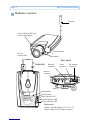
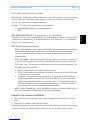
Hardware overview
Dimensions
HxWxD = 38 x 88 x180mm (1.5" x 3.5" x 7")
Weight =260g (0.57 lb) (without antenna)
Network indicator LED
Network
connector
Power indicator LED
Status indicator LED and
Internal microphone
Antenna
Rear panel
Underside
Serial number
Control button
Focus puller
Tele/wide puller
DC-Iris
control cable
I/O terminal
connector
Power
connector
Wireless indicator LED
Antenna
connector
Audio out
Audio in

AXIS 211W Installation Guide Page 5
ENGLISH
ENGLISH
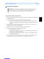
Install the hardware
Connect the cables and antenna
1. For indoor use, attach antenna by screwing it into place. For outdoor use see the outdoor
housing instructions.
2. Connect the camera to the network using a shielded network cable.
• For the wireless models, this connection is temporary and allows the camera’s
settings to be configured via the wired network before connecting to the wireless
network.
3. Optionally connect external input/output devices, e.g. alarm devices. See page 14 for
information on the terminal connector pins.
4. Optionally connect an active speaker and/or external microphone.
5. Connect power, using one of the methods listed below:
• The supplied power connector.
• PoE (Power over Ethernet). If available, this is automatically detected when the
network cable is connected (see above).
• Connect power via the terminal connector. See page 14 for information on the
terminal connector pins.
6. Check that the indicator LEDs indicate the correct conditions. See the table on page 15
for further details. Note that some LEDs can be disabled and may be unlit.
!IMPORTANT! - The AXIS 211W is designed for indoor and outdoor use. To use
the camera outdoors, it must be installed in an approved outdoor housing.
Please see www.axis.com for more information on outdoor housings.

Page 6 AXIS 211W Installation Guide
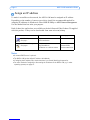
Assign an IP address
To make it accessible on the network, the AXIS 211W must be assigned an IP address.
Depending on the number of cameras you wish to install, the recommended method for
assigning IP addresses in Windows is either AXIS IP Utility or AXIS Camera Management.
Use the method that best suits your purpose.
Both of these free applications are available on the Axis Network Video Product CD supplied
with this product, or they can be downloaded from www.axis.com/techsup
Notes:
• A network DHCP server is optional.
• The AXIS 211W has the default IP address 192.168.0.90
• If assigning the IP address fails, check that there is no firewall blocking the operation.
• For other methods of assigning or discovering the IP address of the AXIS 211W, e.g. in other
operating systems, see page 13.
Method Recommended for Operating system
AXIS IP Utility
See page 7
Single camera
Small installations
Windows
AXIS Camera Management
See page 8
Multiple cameras
Large installations
Installation on a different subnet
Windows 2000
Windows XP Pro
Windows 2003 Server

AXIS 211W Installation Guide Page 7
ENGLISH
ENGLISH
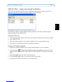
AXIS IP Utility - single camera/small installation
AXIS IP Utility automatically discovers and displays Axis devices on your network. The
application can also be used to manually assign a static IP address.
Note that the computer running AXIS IP Utility must be on the same network segment
(physical subnet) as the AXIS 211W.
Automatic discovery
1. Check that the AXIS 211W is connected to the network and that power has been applied.
2. Start AXIS IP Utility.
3. When the camera appears in the window, double-click it to open its home page.
4. See page 9 for instructions on how to assign the password.
Assign the IP address manually
1. Acquire an unused IP address on the same network segment as your computer.
2. Click the button Assign new IP address using serial number and enter the serial
number and IP address for the AXIS 211W. The serial number is located on the product
label.
3. Click the Assign button and follow the instructions.
4. Click the Home Page button to access the camera’s web pages.
5. See page 9 for instructions on how to set the password.

Page 8 AXIS 211W Installation Guide
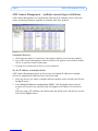
AXIS Camera Management - multiple cameras/large installations
AXIS Camera Management can automatically find and set IP addresses, show connection
status, and manage firmware upgrades for multiple Axis video products.
Automatic discovery
1. Check that the camera is connected to the network and that power has been applied.
2. Start AXIS Camera Management. When the AXIS 211W appears in the window, double-
click it to open the camera’s home page.
3. See page 9 for instructions on how to set the password.
Set the IP address in multiple devices
AXIS Camera Management speeds up the process of assigning IP addresses to multiple
devices, by suggesting IP addresses from a specified range.
1. Select the devices you wish to configure (different models can be selected) and click the
Assign IP button.
2. Select Obtain IP addresses automatically (DHCP), click the Update button and the
program will search in the specified range and suggest an IP address for each device.
-or-
Enter the range of IP addresses, the subnet mask and default router that devices can use
and click the Update button.

AXIS 211W Installation Guide Page 9
ENGLISH
ENGLISH
Set the password
When accessing the AXIS 211W for the first
time, the ‘Configure Root Password’ dialog
will be displayed.
1. Enter a password and then re-enter it, to
confirm the spelling. Click OK.
2. Enter the user name root in the ‘Enter
Network Password’ dialog.
Note: The default administrator user name root cannot be deleted.
3. Enter the password as set above, and click OK. If the password is lost, the AXIS 211W
must be reset to the factory default settings. See page 16.
4. If required, click Yes to install AMC (AXIS Media Control), which allows viewing of the
video stream in Internet Explorer. You will need administrator rights on the computer to
do this.
The Live View page of the AXIS 211W is displayed, with links to the Setup tools, which
allow you to customize the camera.
Setup - Provides all the tools for configuring
the camera to requirements.
Help - Displays
online help on all
aspects of using
the camera.

Page 10 AXIS 211W Installation Guide
Configure the wireless connection
Once the AXIS 211W has been installed on your network, the wireless settings can be
configured. These settings should always (i.e. both during installation and at all other times)
be configured or changed in the camera first and in the wireless access point secondly. This
ensures that the camera is always accessible when making changes.
The AXIS 211W automatically senses the available network connections, and allows only
one of these to be active at a time. Connecting a network cable disables the wireless
connection.
Using a wired connection ensures greater secrecy while making these settings.
Note: For even greater security use HTTPS. Go to Setup > System Options >
Security > HTTPS and refer to the camera’s online help.
Open the wireless settings from Setup > System Options > Network > Wireless. These
settings can also be reached from the Basic Configuration menu.
Status of Wireless Networks
This list is the result of a network scan. Access points with a disabled SSID Broadcast will
not appear unless the camera is associated with it. The network currently associated to is
shown in blue. A network using unsupported security is shown in grey. The following
information is provided:
• SSID - The name of a wireless network (or ad-hoc device). If the same name occurs
several times this means that several access points for that network were found. The
AXIS 211W cannot be configured to only associate with one particular access point.
• Network Type - An Access Point (Master) or Ad-Hoc device.
• Security - Shows which type of security the network uses. See below for the
supported security types.
• Channel - Shows the wireless channel currently in use.
• Signal strength - Shows the signal strength.
• Bit rate - Shows the bit rate in Mbit/s. This can only be shown for the access point
currently in use. Note that the bit rate shown is the current rate, and that this value
may vary over time.
Wireless Settings
These settings control how the AXIS 211W interacts with the wireless network. Apart from
identifying the wireless network, it is also possible to enable wireless encryption.
SSID - This is the name of the wireless network the camera is configured for. The field
accepts up to 32 alphanumeric characters. The name must be exactly the same as that used
in the wireless access point, or the connection will not be established.
Leaving this field blank means the camera will attempt to access the nearest unsecured
network.

AXIS 211W Installation Guide Page 11
ENGLISH
ENGLISH
Note: SSID is sometimes written as ESSID.
Network type - Setting this to Master means the camera will attempt to access the network
via an access point. The Ad-hoc option allows the camera to connect to other wireless
devices, e.g. a laptop with a wireless connection.
Security - The AXIS 211W supports two security methods:
•WPA-PSK/WPA2-PSK (recommended method)
•WEP
WPA-PSK/WPA2-PSK (Wi-Fi Protected Access - Pre-Shared Key)
The AXIS 211W uses a pre-shared key (PSK) for key management. The pre-shared key can be
entered either as Manual hex, as 64 hexadecimal (0-9, A-F) characters, or as a Passphrase,
using 8 to 63 ASCII characters.
WEP (Wired Equivalent Protection)
WEP - Authentication - Select Open or Shared Key System Authentication, depending
on the method used by your access point. Not all access points have this option, in
which case they probably use Open System, which is sometimes known as SSID
Authentication.
WEP - Key length - This sets the length of the key used for the wireless encryption, 64
or 128 bit. The encryption key length can sometimes be shown as 40/64 and 104/128.
WEP - Key Type - The key types available depend on the access point being used. The
following options are available:
• Manual - Allows you to manually enter the hex key.
• ASCII - In this method the string must be exactly 5 characters for 64-bit WEP and
13 characters for 128-bit WEP.
• Passphrase - The passphrase can contain up to 31 characters. In 64-bit WEP, the
Passphrase generates 4 different keys. For 128-bit WEP, only 1 key is generated,
which is then replicated for all 4 keys. Key generation is not standardized and can
differ from brand to brand. Check that the generated keys are identical to those in
your access point - if not, they must be entered manually.
WEP - Active Transmit Key - When using WEP encryption, this selects which of the 4
keys the Productname 3/Productname 2 uses when transmitting.
Complete the wireless installation
1. Check that the wireless settings in the camera correspond to the settings in the access
point.
2. Disconnect the network cable from the camera.
Refresh the web page after 20-30 seconds to confirm the wireless connection. If the camera
cannot be accessed, run AXIS IP Utility to discover the new IP address and try again.

Page 12 AXIS 211W Installation Guide
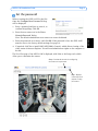
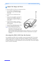
Adjust the image and focus
To focus the AXIS 211W follow the instructions below.
1. From the Basic Configuration page in
the setup tools, open the Focus adjust-
ment page.
2. Set the DC-Iris to Disabled and click
Save.
3. Unscrew the zoom puller on the lens by
turning it anti-clockwise. Adjust the
zoom setting as required. Re-tighten the
zoom puller.
4. Unscrew the focus puller on the lens.
Adjust the focus as required. Re-tighten
the focus puller.
5. From the Focus adjustment page, set the
DC-Iris to Enabled and click Save.
Note: The DC-Iris should always be dis-
abled while focusing the camera. This
opens the iris to its maximum, which
gives the smallest depth of field and thus the best conditions for correct focusing.
When the focus is set with this method it will then be maintained in any light
conditions.
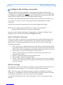
Accessing the AXIS 211W from the Internet
Once installed, your AXIS 211W is accessible on your local network (LAN). To access the
camera from the Internet, network routers must be configured to allow incoming traffic,
which is usually done on a specific port. Please refer to the documentation for your router
for further instructions. For more information on this and other topics, visit the Axis Support
Web at www.axis.com/techsup
Zoom puller
(Tele/wide)
Focus puller

AXIS 211W Installation Guide Page 13
ENGLISH
ENGLISH
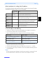
Other methods of setting the IP address
The table below shows the other methods available for setting or discovering the IP address.
All methods are enabled by default, and all can be disabled.
Set the IP address with ARP/Ping
1. Acquire an IP address on the same network segment your computer is connected to.
2. Locate the serial number (S/N) on the AXIS 211W label.
3. Open a command prompt on your computer and enter the following commands:
4. Check that the network cable is connected to the camera and then start/restart the
camera, by disconnecting and reconnecting power.
5. Close the command prompt when you see ‘Reply from 192.168.0.125: ...’ or similar.
6. In your browser, type in http://<IP address> in the Location/Address field and press Enter
on your keyboard.
Notes:
• To open a command prompt in Windows: from the Start menu, select Run... and type cmd. Click OK.
• To use the ARP command on a Mac OS X, use the Terminal utility in Application > Utilities.
Use in operating
system
Notes
UPnP™
Windows
(ME or XP)
When enabled on your computer, the camera is automatically
detected and added to “My Network Places.”
Bonjour MAC OSX
(10.4 or later)
Applicable to browsers with support for Bonjour. Navigate to the
Bonjour bookmark in your browser (e.g. Safari) and click on the
link to access the camera’s web pages.
AXIS Dynamic DNS
Service
All A free service from Axis that allows you to quickly and simply
install your camera. Requires an Internet connection with no
HTTP proxy. See www.axiscam.net for more information.
ARP/Ping All See below. The command must be issued within 2 minutes of
connecting power to the camera.
View DHCP server
admin pages
All To view the admin pages for the network DHCP server, see the
server’s own documentation.
Windows syntax Windows example
arp -s <IP Address> <Serial Number>
ping -l 408 -t <IP Address>
arp -s 192.168.0.125 00-40-8c-18-10-00
ping -l 408 -t 192.168.0.125
UNIX/Linux/Mac syntax UNIX/Linux/Mac example
arp -s <IP Address> <Serial Number> temp
ping -s 408 <IP Address>
arp -s 192.168.0.125 00:40:8c:18:10:00
temp
ping -s 408 192.168.0.125

Page 14 AXIS 211W Installation Guide
Unit connectors
Antenna connector - Reverse SMA connector for antenna.
Network connector - RJ-45 Ethernet connector. Supports Power over Ethernet. Using
shielded cables is recommended.
Power connector - Mini DC connector. 7 - 20V DC, max 5W. See product label for ±
connection.
Audio in - 3.5mm input for a mono microphone, or a line-in mono signal (left channel is
used from a stereo signal).
Audio out - Audio output (line level) that can be connected to a public address (PA) system
or an active speaker with a built-in amplifier. A pair of headphones can also be attached. A
stereo connector must be used for the audio out.
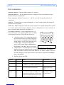
I/O terminal connector - Used in applications for e.g.
motion detection, event triggering, time lapse recording
and alarm notifications. It provides the interface to:
• 1 transistor output - For connecting external
devices such as relays and LEDs. Connected
devices can be activated by AXIS VAPIX AP,
output buttons on the Live View page or by
an Event Type. The output will show as
active (shown under Event Configuration >
Port Status) if the alarm device is activated.
• 1 digital input - An alarm input for connect-
ing devices that can toggle between an open and closed circuit, for example:
PIRs, door/window contacts, glass break detectors, etc. When a signal is received
the state changes and the input becomes active (shown under Event Configura-
tion > Port Status).
• Auxiliary power and GND
Function Pin number Notes Specifications
GND 1
5VDC Power 2 Can be used to power auxiliary equipment
(7-20VDC) or as a +5VDC (100mA) output.
Max load = 100mA
Digital Input 3 Connect to GND to activate, or leave float-
ing (or unconnected) to deactivate.
Must not be exposed to
voltages greater than
20VDC
Transistor
Output
4 Uses an open-collector NPN transistor with
the emitter connected to the GND pin. If
used with an external relay, a diode must be
connected in parallel with the load, for pro-
tection against voltage transients.
Max load = 100mA
Max voltage = 24VDC
(to the transistor)
Pin 1
Pin 3
Pin 2
Pin 4
Terminal connector. Note that the pins
are numbered 1-4, right to left.

AXIS 211W Installation Guide Page 15
ENGLISH
ENGLISH
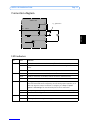
Connection diagram
LED indicators
LED Color Indication
Wireless Green Steady for connection to a wireless network. Flashes for network activity.
Red Steady for no wireless network connection. Flashes when scanning for wireless net-
works.
Unlit Wired mode.
Network Green Steady for connection to a 100 Mbit/s network. Flashes for network activity.
Amber Steady for connection to 10 Mbit/s network. Flashes for network activity.
Unlit No network connection.
Status Green Steady green for normal operation.
Note: The Status LED can be configured to be unlit during normal operation, or to
flash only when the camera is accessed. To configure, go to Setup > System
Options > LED settings. See the online help files for more information.
Amber Steady during startup, during reset to factory default or when restoring settings.
Red Slow flash for failed upgrade.
Power Green Normal operation.
Amber Flashes green/amber during firmware upgrade.
o
z
AXIS 211W
5V
max. 100mA
e.g. pushbutton
4
o
3
o
o
2
1

Page 16 AXIS 211W Installation Guide
Resetting to the Factory Default Settings
This will reset all parameters, including the IP address, to the Factory Default settings:
1. Disconnect power from the camera.
2. Press and hold the Control button and reconnect power.
3. Keep the Control button pressed until the Status indicator displays amber (this may take
up to 15 seconds), then release the button.
4. When the Status indicator displays green (which can take up to 1 minute) the process is
complete and the camera has been reset.
5. Re-assign the IP address, using one of the methods described in this document.
It is also possible to reset parameters to the original factory default settings via the web
interface. For more information, please see the online help or the user’s manual.
Further information
The user’s manual is available from the Axis Web site at www.axis.com or from the Axis
Network Video Product CD supplied with this product.
Tip!
Visit www.axis.com/techsup to check if there is updated firmware available for your
AXIS 211W. To see the currently installed firmware version, see the Basic
Configuration web page in the product’s Setup tools.

Page is loading ...
-
 1
1
-
 2
2
-
 3
3
-
 4
4
-
 5
5
-
 6
6
-
 7
7
-
 8
8
-
 9
9
-
 10
10
-
 11
11
-
 12
12
-
 13
13
-
 14
14
-
 15
15
-
 16
16
-
 17
17
-
 18
18
-
 19
19
-
 20
20
-
 21
21


Axis Communications AB 211W User manual
- Category
- Security cameras
- Type
- User manual
- This manual is also suitable for
Ask a question and I''ll find the answer in the document
Finding information in a document is now easier with AI
Related papers

Other documents
-
Axis Communications 211W User manual
-
-
Axis Communications AXIS 211W User manual
-
Axis 0270-024 Datasheet
-
Axis Axis 211 User manual
-
-
-
-
-