Page is loading ...

BLACKMER BYPASS VALVES 967020
INSTRUCTIONS NO. 551-E00
INSTALLATION OPERATION AND MAINTENANCE INSTRUCTIONS
EBSRAY MODEL: RV18
Section
Effective
Replaces
551
Aug 2015
Nov 2014
RV18CBS2, RV18CBS3, RV18VRS10, RV18VRS14, RV18VRS19
TABLE OF CONTENTS Page
GENERAL
Description ............................................................ 2
Nameplate codes .................................................. 2
INSTALLATION
Piping .................................................................... 3
Checking the External Bypass Valve Pressure ..... 3
Bypass Valve Adjustment ...................................... 4
Operational Checks ............................................... 4
MAINTENANCE
Periodic Inspection ................................................... 4
Preparation for Disassembly .................................... 5
Disassembly ............................................................. 5
Inspection ................................................................. 5
Reassembly ............................................................. 5
PARTS DESIGNATION ................................................... 6
Numbers in parentheses following individual parts indicate
reference numbers on Parts Designation page.
Blackmer instruction manuals and parts lists may be obtained
from Blackmer's website (www.blackmer.com) or by
contacting Blackmer Customer Service.
SAFETY DATA
This is a SAFETY ALERT SYMBOL.
When you see this symbol on the product, or in the manual,
look for one of the following signal words and be alert to the
potential for personal injury, death or major property
damage
Warns of hazards that WILL cause serious personal injury,
death or major property damage.
Warns of hazards that CAN cause serious personal injury,
death or major property damage.
Warns of hazards that CAN cause personal injury
or property damage.
NOTICE:
Indicates special instructions which are very
important and must be followed.
NOTICE:
Blackmer external bypass valves MUST only be
installed in systems which have been designed by
qualified engineering personnel. The system MUST
conform to all applicable local and national
regulations and safety standards.
This manual is intended to assist in the installation
and operation of Blackmer bypass valves, and MUST
be kept with the bypass valve.
Blackmer bypass valve service shall be performed by
qualified technicians ONLY. Service shall conform to
all applicable local and national regulations and
safety standards.
Thoroughly review this manual, all Instructions and
hazard warnings, BEFORE performing any work on
the Blackmer bypass valves.
Maintain ALL system and Blackmer liquefied gas
pump operation and hazard warning decals.

551-E00 page 2/6
SAFETY DATA
Failure to disconnect and lockout
electrical power or engine drive before
attempting maintenance can cause
severe personal injury or death
If pumping hazardous or toxic fluids,
system must be flushed and
decontaminated, inside and out, prior to
performing service or maintenance
Hazardous
machinery can
cause serious
personal injury. Hazardous or toxic
fluids can cause
serious injury.
Disconnecting fluid or pressure
containment components during pump
operation can cause serious personal
injury or property damage.
Failure to relieve system pressure prior
to performing external bypass or pump
service can cause serious personal
injury or property damage. Systems
with meters will still be pressurized
even after the hose is emptied
Hazardous pressure
can cause serious
personal injury or
property damage Hazardous pressure
can cause serious
personal injury or
property damage
NOTICE
Blackmer bypass valves must only be installed in LPG systems that have been designed by qualified engineering personnel
and operated and maintained by qualified technicians. The system must conform to all applicable local and national
regulations and safety standards (specifically, lpg systems must conform to NFPA 58). This manual must be kept with the
bypass valve and be reviewed before installation, putting into operation or performing any maintenance work.
DESCRIPTION
The EBSRAY Models RV18 Bypass Valves are intended to
enable control and setting of pump and system differential
pressures only. They are spring actuated devices that by
design cannot be positively shut-off.
These Bypass Valves are listed by Underwriters’ Laboratories
for liquefied petroleum gas (LPG) service
Two configuration options are available:
1. Constant Bleed System (CBS) option which provides for
controlled 'bleed-off' of vapor enhancing self priming and
vapor clearing capabilities of the pump.
2. Vapor Removal System (VRS) option which provides rapid
flow-through of vapor until liquid reaches the valve and then
closes off the vapor orifice for maximum pump efficiency.
i.e. fulfils an excess-flow valve type of function.
Technical Data is for standard materials of construction.
Consult Blackmer Material Specs for optional materials of
construction.
The Ebsray RV Model No. Code on the Nameplate identifies
the valve type and spring fitted to the Bypass valve.
Example: RV18CBS2-023-02U01
Spring Code
RV18 Springs
Spring
Code Working Differential
Pressure Range
Maximum Differential
Pressure at the Rated
Maximum Flow
01 550 to 950 kPa
(80 to 138 PSID) 1050 kPa at 200 litre/min
(152 PSID at 53 US GPM)
02 600 to 1350 kPa
(87 to 196 PSID) 1440 kPa at 200 litre/min
(210 PSID at 53 US GPM

551-E00 page 3/6
INSTALLATION
INSTALLATION
On liquefied gas systems, an external bypass valve, piped
back to the supply tank, is necessary for maximum pump
performance and longer pump life. The bypass valve must
be installed in the correct position on the discharge side of
the pump. (The word “IN” is cast on the inlet port of the
bypass valves.) The bypass valve will automatically prevent
excessive pressure resulting from accidental pump
overspeeding, discharge shut-off, or highly restrictive
receiving systems.
Correct installation and operation is essential. Service life is
enhanced by periodic inspection and careful maintenance.
Size the external bypass valve and its piping to
accommodate the full flow from the pump when the pump's
discharge line is closed and the pump is running at its rated
maximum speed.
When installing the external bypass valve, it is essential that
the pipe and fittings from the discharge port of the bypass
valve be sized properly. Excessive backpressure resulting
from friction loss in the bypass valve discharge piping will
cause a higher pressure than the actual bypass valve
setting.
For more information on sizing and friction loss, refer to the
Blackmer Liquefied Gas Handbook - Bulletin 500-001 (or
Bulletin 33 for other liquids) for pipe friction tables.
On liquefied gas systems, the external bypass valve
discharge must be piped back to the liquid or vapor
section of the supply tank never to the pump inlet. This
method of piping should also be used when pumping volatile
liquids from an underground tank or at high vacuum.
NOTICE
NEVER allow water or any corrosive product to enter
the Bypass Valve (e.g. for hydrostatic testing of
pipework). Severe internal damage may result.
If the Bypass Valve is not installed and commissioned
immediately, special preservative techniques will be
required. Low pressure nitrogen can be used to purge,
seal and protect the Bypass Valve from the effects of
condensation and atmospheric corrosion. Alternately a
¼ cup (60 mL) of diesel may be poured into the valve.
PIPING
The bypass valve should be installed
with the adjusting screw in the 12
O'clock (up) position. Mounting the
valve horizontally may cause
increased wear on the spool valve.
Flow must be into the port marked
"IN".
Remove pipe scale and other foreign
material such as PTFE tape residue
from the connecting pipelines. Apply
a suitable pipe thread sealant to the
male threads before fitting.
Never draw piping into place by use of
force at the port connections of the
Bypass Valve.
All piping should be supported
independently and line up accurately
with the Bypass Valve ports.
NOTICE:
At temperatures below -20° F (-28.9° C) materials have
reduced impact strength. Provisions should be made to
prevent tools and other objects from impacting any
pressure containing components of the pumping system.
CHECKING THE EXTERNAL BYPASS VALVE
PRESSURE
1. Install a pressure gauge equipped with a needle valve or
snubber in the pump discharge gauge port. Install a
pressure gauge on the tank and record the tank pressure.
2. Connect the delivery hose to the receiving tank.
3. Check all valves. The shut-off valve in the pump's discharge
line and the shut-off valve in the bypass return line should be
open.
4. Start pumping at the normal rate. Make sure the supply tank
outlet valve is wide open and check the direction of shaft
rotation to be sure it matches the direction of the arrow on
the pump.
5. To check the external bypass valve setting, gradually close
the shut-off valve in the pump's discharge line and record
the gauge pressure. The difference between this reading
and the tank pressure (before pumping) is the external
bypass valve setting.
6. For pumps with an internal relief valve (i.e., most PD pumps):
The external bypass valve must be set at least 25 psi (1.72
bar) less than the pump's internal relief valve setting.
To check the pump's internal relief valve pressure setting:
Gradually close the shut-off valve in the bypass return line.
Then slowly close the shut-off valve in the pump's
discharge line while watching the gauge pressure on the
discharge side of the pump. Record the peak differential
pressure (the difference between the discharge and inlet
pressure) when the internal relief valve begins to open.
NOTE: It is important to read the peak pressure just before
the pump relief valve opens. Once recirculation starts
through the pump relief valve, vaporization will cause the
pressure to fall quickly. For more information on the pump
relief valve settings and adjustments, refer to the
installation instructions for the specific pump.
After the internal relief valve setting has been determined,
reopen the shut-off valve in the pump's discharge line and
the shut-off valve in the bypass return line.
External bypass valves shall be sized
and adjusted so the maximum pressure
of the system does not exceed the
lowest service pressure rating of any
component used in the delivery system.
Hazardous pressure
can cause serious
personal injury or
property damage

551-E00 Page 4/6
INSTALLATION
EXTERNAL BYPASS VALVE ADJUSTMENT
1. Remove the seal wire and loosen the locknut (10).
2. To increase the pressure setting, slowly turn the
adjusting screw (8) inward, or clockwise.
3. To reduce the pressure setting, slowly turn the adjusting
screw (8) outward, or counterclockwise.
4. Ensure that there is an appropriate pressure gauge fitted
to Pumps’ main discharge viewable while setting the
Bypass Valve.
5. Rotate the Bypass Adjusting Screw (8) anti-clockwise
until there is no resistance against the screw. This is the
Bypass Valve's minimum pressure setting.
6. Ensure that the system is set such that 100% of the
Pump’s flow is directed through the Bypass Valve
7. Start the Pump and ensure that liquid is flowing through
Bypass Valve. This should be detectable audibly (by
listening) or by feeling the valve/pipework (by hand).
8. Screw in the Bypass Valve Adjusting Screw (8) not
exceeding two turns per minute until the desired
differential pressure is reached.
9. While retaining the Adjustment Screw (8), tighten the
Locknut (10) against the Bypass Valve Cover (2).
10. After setting the Bypass Valve is completed, wire and seal
the Adjusting Screw, using the holes provided in the head
of Adjusting Screw and lug on Bypass Valve Cover.
NOTE: Bypass Valves characteristically exhibit two distinct
pressures during their operation:
1) The ‘setting‘ or ‘cracking’ pressure which occurs when the
Bypass Valve first opens i.e. initial bypassing begins against
the preset spring load.
2) ‘Maximum’ pressure, which occurs when the full flow of the
bypassed product passes through the Bypass Valve.
It is important to ensure both these above characteristics are
understood fully in order to correctly apply the Bypass Valve.
OPERATIONAL CHECKS
Inspect the external Bypass Valve frequently during the first few
hours of operation for such conditions as leaks, excessive
heating, vibration or unusual noises etc.
MAINTENANCE
Failure to disconnect and lockout
electrical power or engine drive before
attempting maintenance can cause
severe personal injury or death
Hazardous
machinery can cause
serious personal
injury.
Disconnecting fluid or pressure
containment components during pump
operation can cause serious personal
injury or property damage.
Hazardous pressure
can cause serious
personal injury or
property damage
If pumping hazardous or toxic fluids,
system must be flushed and
decontaminated, inside and out, prior
to performing service or maintenance
Hazardous or toxic
fluids can cause
serious injury.
Failure to relieve system pressure prior
to performing pump service can cause
serious personal injury or property
damage. Systems with meters will still
be pressurized even after the hose is
emptied
Hazardous pressure
can cause serious
personal injury or
property damage
NOTICE:
Maintenance shall be performed by qualified technicians
only. Follow the appropriate procedures and warnings
as presented in this manual.
LUBRICATION
No ‘in service’ lubrication is required on Ebsray Model RV18
Bypass Valves.
PERIODIC INSPECTION
Periodic Inspection of the Bypass Valve, Pump System and
Ancillary Equipment is required to maintain safety, conformity,
operational functionality and reliability.
Annual inspection and testing of the internal relief valve
(if applicable) and the external bypass valve operation
and setting is recommended.
Maintenance inspections should be performed at a maximum
interval of three months or 500 hours operation. More
frequent inspections may be necessary dependent upon
usage, site conditions, operation, etc.
If any abnormal condition is discovered, cease operation of
pump system immediately and take action to rectify the
problem.
For safe operation, the following items should be included in
the routine periodic inspection:
a. Inspect the Bypass Valve for leaks, vibration, abnormal
noises, signs of overheating, discoloration, etc.
b. Check Bypass Valve differential pressure setting.

551-E00 Page 5/6
MAINTENANCE
PREPARATION FOR DISASSEMBLY
1. Isolate Bypass Valve from liquids/vapor in inlet and
discharge lines, depressurize and purge any toxic,
flammable, corrosive or air hardening liquid/vapor.
2. Ensure the associated Pump Motor power supply has been
isolated, before proceeding with disassembly.
3. Once exposed to the atmosphere, immediately protect the
valve with from corrosion. A ¼ cup (60 mL) of diesel may
be poured into the valve
DISASSEMBLY
Refer to the Parts Designation drawings.
1. Unlock Adjusting Screw Locknut (10).
2. Release Spring pressure by rotating Adjusting Screw (8)
anti-clockwise.
3. Unscrew four Capscrews (9) holding Valve Cover (2) onto
Housing (1). NOTE: There will be a slight spring pre-
compression remaining.
4. Remove the Valve Cover (2) and O-Ring (2), together with
the Spring Cap (2) and its O-Ring (6).
5. Remove Spring Cap (2) and O-Ring (6) from Valve Cover
(2).
6. Remove Spring (5) and Valve (3a, 3b) from Housing (1).
7. VRS OPTION ONLY: Carefully remove Circlip (14) from
inside Valve (3a), then remove Ball (12) and Spring-Vent
(13).
INSPECTION
1. Inspect Housing (1) and valve bore for damage or wear. If
required, remove Housing and replace.
2. Check Valve (3a, 3b) for damage or wear. If required,
replace valve.
3. Inspect Spring - Bypass (5), replace if broken or damaged.
4. It is advised that O-Rings (6, 7) be replaced at every
overhaul.
5. Check Valve Cover (2), Spring Cap (4), Adjusting Screw (8)
and Locknut (10) for damage. Replace as required.
6. VRS OPTION ONLY: Check condition of Ball (12), Spring -
Vent (13) and Circlip (14). Replace as required.
REASSEMBLY
Refer to the Parts Designation drawings.
4. VRS OPTION ONLY: Insert Spring - Vent (13) into Valve
(3a) with large end seating in Valve, insert Ball (12) after
Spring - Vent and retain in place with Circlip (14), ensuring
Circlip locates correctly in groove.
5. Fit Valve (3a, 3b) into Housing (1), ensuring freedom of
movement.
6. Fit Spring - Bypass (5) on to top of Valve (3a, 3b).
7. Lightly smear all O-Rings (6, 7) with a compatible good
quality detergent free, light oil before assembly.
8. Fit O-Ring (7) to Valve Cover (2).
9. Fit O-Ring (6) to Spring Cap (4) and insert into Valve Cover
(2) with spring location boss facing out.
10. Fasten Valve Cover (2) to Housing (1) using four
capscrews (9). Torque to 16 ft-lb (22 N-m).
11. After recommissioning, adjust differential pressure as per
‘BYPASS VALVE ADJUSTMENT’.

551-E00 Page 6/6
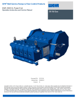
PARTS DESIGNATION
MODELS: RV18 Inline Bypass Valves.
Ref. Description Qty Ref. Description Qty
1 Housing NPT 1 7 0-Ring, 1/8x2 1
2 Valve Cover 1 8 Adjusting Screw 1
3a Valve 1 9 Socket Hd Capscrew M8x1.25x25 4
3b Valve 1 10 Nut Hexagon Head Metric 1
4 Spring Cap 1 12 Ball 1
5 Spring Bypass 1 13 Spring Vent 1
6 0-Ring, 1/8x1-7/16 1 14 Circlip 1
Spare Parts Inquiries
To facilitate Parts inquiries, please provide Blackmer with:
a. Model and Serial Number on the valve nameplate.
b. Ref. # and Description from the Parts Designation table.
c. Quantity required.
Visit www.blackmer.com for complete information on all Blackmer products
1809 Century Avenue, Grand Rapids, Michigan 49503-1530 U.S.A.
Telephone: (616) 241-1611 • Fax: (616) 241-3752
E-mail: [email protected] • Internet Address: www .blackmer.com
/