Linksys SRW2024 User manual

Category
Networking
Type
User manual

This manual is also suitable for

A Division of Cisco Systems, Inc.
®
Model No.
WIRED with WebView
16- or 24-Port 10/100/1000 Gigabit Switch
SRW2016 or SRW2024
User Guide
16- or 24-Port 10/100/1000 Gigabit Switch with WebView
Copyright and Trademarks
Specifications are subject to change without notice. Linksys is a registered trademark or trademark of Cisco
Systems, Inc. and/or its affiliates in the U.S. and certain other countries. Copyright © 2005 Cisco Systems, Inc. All
rights reserved. Other brands and product names are trademarks or registered trademarks of their respective
holders.
How to Use this Guide
Your guide to the 16- or 24-Port 10/100/1000 Gigabit Switch with WebView has been designed to make
understanding networking with the switch easier than ever. Look for the following items when reading this User
Guide:
In addition to these symbols, there are definitions for technical terms that are presented like this:
Also, each figure (diagram, screenshot, or other image) is provided with a figure number and description, like
this:
Figure numbers and descriptions can also be found in the “List of Figures” section.
This exclamation point means there is a caution or
warning and is something that could damage your
property or the Switch.
word: definition.
This checkmark means there is a note of interest and
is something you should pay special attention to while
using the Switch.
This question mark provides you with a reminder about
something you might need to do while using the Switch.
Figure 0-1: Sample Figure Description
SRW2016_SRW2024-UG-50429C JL
WARNING: This product contains chemicals, including lead, known
to the State of California to cause cancer, and birth defects or other
reproductive harm. Wash hands after handling.
16- or 24-Port 10/100/1000 Gigabit Switch with WebView
Table of Contents
Chapter 1: Introduction 1
Welcome 1
What’s in this User Guide? 2
Chapter 2: Getting to Know the Switch 3
Overview 3
The Front Panel 3
The Back Panel 4
Chapter 3: Connecting the Switch 5
Overview 5
Before You Install the Switch... 6
Placement Options 6
Connecting the Switch 7
Chapter 4: Using the Console Interface for Configuration 9
Overview 9
Configuring the HyperTerminal Application 9
Configuring the Switch through the Console Interface 10
Chapter 5: Using the Web-based Utility for Configuration 18
Overview 18
Accessing the Web-based Utility 18
Sys. Info. (System Information) Tab - System Description 18
Sys. Info. (System Information) Tab - System Mode 19
Sys. Info. (System Information) Tab - Forwarding Database 19
Sys. Info. (System Information) Tab - Time Synchronization 20
IP Conf. (Configuration) Tab - IP Addr. (Address) 21
Switch Conf. (Configuration) Tab - Interface Conf. (Configuration) 21
Switch Conf. (Configuration) Tab - VLAN 24
Switch Conf. (Configuration) Tab - VLAN Port 24
Switch Conf. (Configuration) Tab - LA Conf. (Configuration) 25
Switch Conf. (Configuration) Tab - Port Mirroring 26
Switch Conf. (Configuration) Tab - LACP 26
QoS Tab - CoS Settings 27
QoS Tab - Queue Settings 27
16- or 24-Port 10/100/1000 Gigabit Switch with WebView
QoS Tab - CoS to Queue 28
Security Tab - ACL 28
Security Tab - 802.1x Users 29
Security Tab - 802.1x Port Conf. (Configuration) 29
Security Tab - Management Conf. (Configuration) 31
Security Tab - RADIUS Server 31
Security Tab - TACACS Server 33
Security Tab - Storm Control 34
Security Tab - Authenticated Users 35
Security Tab - System Password 35
SNTP Tab - Global Settings 35
SNTP Tab - Authentication 36
SNTP Tab - Servers 37
SNTP Tab - Interface Settings 38
Statistics Tab - Interface Statistics 39
Statistics Tab - Etherlike Statistics 40
Statistics Tab - RMON Statistics 41
Statistics Tab - RMON History Control 42
Statistics Tab - RMON History Log 43
Statistics Tab - RMON Alarms 44
Statistics Tab - RMON Events Control 45
Statistics Tab - RMON Events Log 46
Statistics Tab - EAP Statistics 47
Logs Tab - Message Log 47
Logs Tab - Event Log 48
Logs Tab - Global Parameters 48
Maintenance Tab - Telnet 49
Maintenance Tab - Reset 49
Maintenance Tab - File Download 49
Maintenance Tab - File Upload 50
Maintenance Tab - Restore Defaults 51
Maintenance Tab - Integrated Cable Test 51
Maintenance Tab - HTTP File Download 52
Help Tab 52
16- or 24-Port 10/100/1000 Gigabit Switch with WebView
Appendix A: About Gigabit Ethernet and Fiber Optic Cabling 53
Gigabit Ethernet 53
Fiber Optic Cabling 53
Appendix B: Windows Help 54
Appendix C: Glossary 55
Appendix D: Specifications 61
Appendix E: Warranty Information 62
Appendix F: Regulatory Information 63
Appendix G: Contact Information 64
16- or 24-Port 10/100/1000 Gigabit Switch with WebView
List of Figures
Figure 2-1: Front Panel of the 16-Port Switch 3
Figure 2-2: Back Panel of the 16-Port Switch 4
Figure 3-1: Typical Network Configuration for the 16-Port Switch 5
Figure 3-2: Attach the Brackets to the Switch 7
Figure 3-3: Mount the Switch in the Rack 7
Figure 4-1: Finding HyperTerminal 9
Figure 4-2: Connection Description 9
Figure 4-3: Connect To 9
Figure 4-4: COM1 Properties 10
Figure 4-5: Switch Main Menu 10
Figure 4-6: System Configuration Menu 11
Figure 4-7: System Information 11
Figure 4-8: Versions 11
Figure 4-9: General System Information 12
Figure 4-10: Management Settings 12
Figure 4-11: Serial Port Configuration 12
Figure 4-12: Telnet Configuration 13
Figure 4-13: IP Configuration 13
Figure 4-14: IP Address Configuration 13
Figure 4-15: HTTP 14
Figure 4-16: Network Configuration 14
Figure 4-17: Ping 15
Figure 4-18: Ping Test Results 15
Figure 4-19: TraceRoute 15
Figure 4-20: TraceRoute Test Results 16
Figure 4-21: File Management 16
Figure 4-22: System Configuration Menu 16
Figure 4-23: Port Status 17
16- or 24-Port 10/100/1000 Gigabit Switch with WebView
Figure 4-24: Port Configuration 17
Figure 4-25: Help 17
Figure 5-1: Login Screen 18
Figure 5-2: System Information - System Description 18
Figure 5-3: System Information - System Mode 19
Figure 5-4: System Information - Forwarding Database 19
Figure 5-5: Forwarding Database - Add Entry 20
Figure 5-6: System Information - Time Synchronization 20
Figure 5-7: IP Configuration - IP Address 21
Figure 5-8: Switch Configuration - Interface Configuration 21
Figure 5-9: Interface Configuration - Change Settings 22
Figure 5-10: Switch Configuration - VLAN 24
Figure 5-11: VLAN - Add VLAN 24
Figure 5-12: Switch Configuration - VLAN Port 24
Figure 5-13: VLAN Port - Change Settings 25
Figure 5-14: Switch Configuration - LA Configuration 25
Figure 5-15: LA Configuration - Change Settings 25
Figure 5-16: Switch Configuration - Port Mirroring 26
Figure 5-17: Switch Configuration - LACP 26
Figure 5-18: LACP - Change Settings 26
Figure 5-19: QoS - CoS Settings 27
Figure 5-20: QoS - Queue Settings 27
Figure 5-21: QoS - CoS to Queue 28
Figure 5-22: Security Tab - ACL 28
Figure 5-23: ACL - Add Access Profile 28
Figure 5-24: Security - 802.1x Users 29
Figure 5-25: Security - 802.1x Port Configuration 29
Figure 5-26: 802.1x Port Configuration - Change Settings 30
Figure 5-27: Security - Management Configuration 31
Figure 5-28: Security - RADIUS Server 31
16- or 24-Port 10/100/1000 Gigabit Switch with WebView
Figure 5-29: RADIUS Server - Change Settings 32
Figure 5-30: Security - TACACS Server 33
Figure 5-31: TACACS Server - Change Settings 33
Figure 5-32: Security - Storm Control 34
Figure 5-33: Security - Authenticated Users 35
Figure 5-34: Security - System Password 35
Figure 5-35: SNTP - Global Settings 35
Figure 5-36: SNTP - Authentication 36
Figure 5-37: Authentication - Modify Settings 36
Figure 5-38: SNTP - Servers 37
Figure 5-39: Servers - Change Settings 38
Figure 5-40: SNTP - Interface Settings 38
Figure 5-41: Interface Settings - Change Settings 38
Figure 5-42: Statistics - Interface Statistics 39
Figure 5-43: Statistics - Etherlike Statistics 40
Figure 5-44: Statistics - RMON Statistics 41
Figure 5-45: Statistics - RMON History Control 42
Figure 5-46: RMON History Control - Add Entry 42
Figure 5-47: Statistics - RMON History Log 43
Figure 5-48: Statistics - RMON Alarms 44
Figure 5-49: RMON Alarms - Add Entry 45
Figure 5-50: Statistics - RMON Events Control 45
Figure 5-51: RMON Events Control - Add Entry 46
Figure 5-52: Statistics - RMON Events Log 46
Figure 5-53: Statistics - EAP Statistics 47
Figure 5-54: Logs - Message Log 47
Figure 5-55: Logs - Event Log 48
Figure 5-56: Logs - Global Parameters 48
Figure 5-57: Maintenance - Telnet 49
Figure 5-58: Maintenance - Reset 49
16- or 24-Port 10/100/1000 Gigabit Switch with WebView
Figure 5-59: Maintenance - File Download 49
Figure 5-60: File Download - Configuration Download 50
Figure 5-61: Maintenance - File Upload 50
Figure 5-62: File Upload - Configuration Upload 51
Figure 5-63: Maintenance - Restore Defaults 51
Figure 5-64: Maintenance - Integrated Cable Test 51
Figure 5-65: Integrated Cable Test - Perform Test 52
Figure 5-66: Maintenance - HTTP File Download 52
Figure 5-67: Help - System Description 52
1
Chapter 1: Introduction
Welcome
16- or 24-Port 10/100/1000 Gigabit Switch with WebView
Chapter 1: Introduction
Welcome
Thank you for choosing the 16- or 24-Port 10/100/1000 Gigabit Switch with WebView. This Switch will allow you
to network better than ever.
This new Linksys rackmount switch delivers non-blocking, wire speed switching for your 10, 100, and 1000Mbps
network clients, plus multiple options for connecting to your network backbone. 16 or 24, 10/100/1000 ports wire
up your workstations or connect to other switches and the backbone. And the mini-GBIC ports allow future
expansion to alternate transmission media, such as fiber optic cabling.
The Switch features WebView monitoring and configuration via your web browser, making it easy to manage your
VLANs and trunking groups. Or if you prefer, you can use the Switch’s console interface to configure the Switch.
Use the instructions in this User Guide to help you connect the Switch, set it up, and configure it to bridge your
different networks. These instructions should be all you need to get the most out of the 16- or 24-Port
10/100/1000 Gigabit Switch with WebView.
2
Chapter 1: Introduction
What’s in this User Guide?
16- or 24-Port 10/100/1000 Gigabit Switch with WebView
What’s in this User Guide?
This user guide covers the steps for setting up and using the Switch.
Chapter 1: Introduction
This chapter describes the Switch’s applications and this User Guide.
Chapter 2: Getting to Know the Switch
This chapter describes the physical features of the Switch.
Chapter 3: Connecting the Switch
This chapter explains how to install and connect the Switch.
Chapter 4: Using the Console Interface for Configuration
This chapter instructs you on how to use the Switch’s console interface when you configure the Switch.
Chapter 5: Using the Web-based Utility for Configuration
This chapter shows you how to configure the Switch using the Web-based Utility.
Appendix A: About Gigabit Ethernet and Fiber Optic Cabling
This appendix gives a general description of Gigabit Ethernet and fiber optic cabling.
Appendix B: Windows Help
This appendix describes how you can use Windows Help for instructions about networking, such as installing
the TCP/IP protocol.
Appendix C: Glossary
This appendix gives a brief glossary of terms frequently used in networking.
Appendix D: Specifications
This appendix provides the Switch’s technical specifications.
Appendix E: Warranty Information
This appendix supplies the Switch’s warranty information.
Appendix F: Regulatory Information
This appendix supplies the Switch’s regulatory information.
Appendix G: Contact Information
This appendix provides contact information for a variety of Linksys resources, including Technical Support.
3
Chapter 2: Getting to Know the Switch
Overview
16- or 24-Port 10/100/1000 Gigabit Switch with WebView
Chapter 2: Getting to Know the Switch
Overview
The 16- and 24-Port Switches differ in number of LEDs and ports. Pictured in this chapter is the 16-Port Switch;
however, the other Switch is similar in form and function.
The Front Panel
The Switch's LEDs and ports are located on the front panel.
LEDs
SYSTEM Green. The SYSTEM LED lights up to indicate that the Switch is powered on.
Link/Act Green. The Link/Act LED lights up to indicate a functional network link through the
corresponding port (1 through 16 or 1 through 24) with an attached device. It flashes to
indicate that the Switch is actively sending or receiving data over that port.
Gigabit Orange. The Gigabit LED lights up to indicate a Gigabit connection on the corresponding
port (1 through 16 or 1 through 24).
Ports
1-24 The Switch is equipped with 16 or 24 auto-sensing, Ethernet network ports, which use RJ-
45 connectors. These ports support network speeds of 10Mbps, 100Mbps, and 1000Mbps.
They can operate in half and full-duplex modes. Auto-sensing technology enables each
port to automatically detect the speed of the device connected to it (10Mbps, 100Mbps, or
1000Mbps), and adjust its speed and duplex accordingly.
Figure 2-1: Front Panel of the 16-Port Switch
4
Chapter 2: Getting to Know the Switch
The Back Panel
16- or 24-Port 10/100/1000 Gigabit Switch with WebView
For the 16-Port Switch, ports 8 and 16 are shared with miniGBIC1 and miniGBIC2,
respectively. For the 24-Port Switch, ports 12 and 24 are shared with miniGBIC1 and
miniGBIC2, respectively.
miniGBIC1/2 The Switch provides two mini-GBIC ports. The mini-GBIC (gigabit interface converter) port
is a connection point for a mini-GBIC expansion module, so the Switch can be uplinked via
fiber to another switch. Each mini-GBIC port provides a link to a high-speed network
segment or individual workstation at speeds of up to 1000Mbps.
Use the Linksys MGBT1, MGBSX1, or MGBLH1 mini-GBIC modules with the Switch. The
MGBSX1 and the MGBLH1 require fiber cabling with LC connectors, while the MGBT1
requires a Category 5e Ethernet cable with an RJ-45 connector.
Console The Console port is where you can connect a serial cable to a PC’s serial port for
configuration using your PC’s HyperTerminal program. Refer to “Chapter 4: Using the
Console Interface for Configuration” for more information.
The Back Panel
The power port is located on the back panel of the Switch.
Power The Power port is where you will connect the power cord.
Figure 2-2: Back Panel of the 16-Port Switch
NOTE: If you need to reset the Switch, unplug the power cord from the back
of the Switch. Wait a few seconds and then reconnect it.
NOTE: If shared ports are both connected, then the miniGBIC port has priority.
5
Chapter 3: Connecting the Switch
Overview
16- or 24-Port 10/100/1000 Gigabit Switch with WebView
Chapter 3: Connecting the Switch
Overview
This chapter will explain how to connect network devices to the Switch. For an example of a typical network
configuration, see the application diagram shown below.
When you connect your network devices, make sure you don’t exceed the maximum cabling distances, which are
listed in the following table:
*A hub refers to any type of 100Mbps hub, including regular hubs and stackable hubs. A 10Mbps hub connected
to another 10Mbps hub can span up to 100 meters (328 feet).
Table 1: Maximum Cabling Distances
From To Maximum Distance
Switch Switch or Hub* 100 meters (328 feet)
Hub Hub 5 meters (16.4 feet)
Switch or Hub Computer 100 meters (328 feet)
Figure 3-1: Typical Network Configuration for the 16-Port Switch
6
Chapter 3: Connecting the Switch
Before You Install the Switch...
16- or 24-Port 10/100/1000 Gigabit Switch with WebView
Before You Install the Switch...
When you choose a location for the Switch, observe the following guidelines:
Make sure that the Switch will be accessible and that the cables can be easily connected.
Keep cabling away from sources of electrical noise, power lines, and fluorescent lighting fixtures.
Position the Switch away from water and moisture sources.
To ensure adequate air flow around the Switch, be sure to provide a minimum clearance of two inches
(50 mm).
Do not stack free-standing Switches more than four units high.
Placement Options
Before connecting cables to the Switch, first you will physically install the Switch. Either set the Switch on its four
rubber feet for desktop placement or mount the Switch in a standard-sized, 19-inch wide, 1U high rack for rack-
mount placement.
Desktop Placement
1. Attach the rubber feet to the recessed areas on the bottom of the Switch.
2. Place the Switch on a desktop near an AC power source.
3. Keep enough ventilation space for the Switch and check the environmental restrictions mentioned in the
specifications.
4. Proceed to the section, “Connecting the Switch.
7
Chapter 3: Connecting the Switch
Connecting the Switch
16- or 24-Port 10/100/1000 Gigabit Switch with WebView
Rack-Mount Placement
To mount the Switch in any standard-sized, 19-inch wide, 1U high rack, follow these instructions:
1. Place the Switch on a hard flat surface with the front panel facing you.
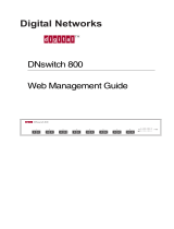
2. Attach a rack–mount bracket to one side of the Switch with the supplied screws. Then attach the other
bracket to the other side.
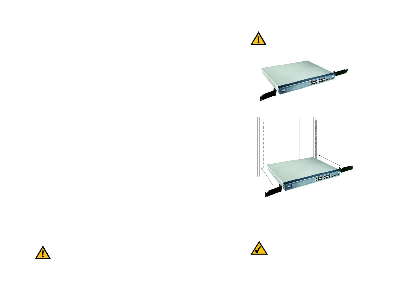
3. Make sure the brackets are properly attached to the Switch.
4. Use the appropriate screws (not included) to securely attach the brackets to your rack.
5. Proceed to the section, “Connecting the Switch.
Connecting the Switch
To connect network devices to the Switch, follow these instructions:
1. Make sure all the devices you will connect to the Switch are powered off.
2. For a 10/100Mbps devices, connect a Category 5 Ethernet network cable to one of the numbered ports on the
Switch. For a 1000Mbps device, connect a Category 5e Ethernet network cable to one of the numbered ports
on the Switch.
3. Connect the other end to a PC or other network device.
4. Repeat steps 2 and 3 to connect additional devices.
5. If you are using the mini-GBIC port, then connect the mini-GBIC module to the mini-GBIC port. For detailed
instructions, refer to the module’s documentation.
6. If you will use the Switch’s console interface to configure the Switch, then connect the supplied serial cable
to the Switch’s Console port, and tighten the captive retaining screws. Connect the other end to your PC’s
serial port. (This PC must be running the VT100 terminal emulation software, such as HyperTerminal.)
7. Connect the supplied power cord to the Switch’s power port, and plug the other end into an electrical outlet.
Figure 3-2: Attach the Brackets to the Switch
NOTE: If you need to reset the Switch, unplug the
power cord from the back of the Switch. Wait a
few seconds and then reconnect it.
IMPORTANT: Make sure you use the power cord that is supplied with the Switch. Use of a
different power cord could damage the Switch.
IMPORTANT: Make sure you use the screws
supplied with the mounting brackets. Using the
wrong screws could damage the Switch and would
invalidate your warranty.
Figure 3-3: Mount the Switch in the Rack
8
Chapter 3: Connecting the Switch
Connecting the Switch
16- or 24-Port 10/100/1000 Gigabit Switch with WebView
8. Power on the network devices connected to the Switch. Each active port’s corresponding Link/Act LED will
light up on the Switch. If a port has an active Gigabit connection, then its corresponding Gigabit LED will also
light up.
If you will use the Switch’s console interface to configure the Switch, proceed to “Chapter 4: Using the Console
Interface for Configuration” for directions.
If you will use the Switch’s Web-based Utility to configure the Switch, proceed to “Chapter 5: Using the Web-
based Utility for Configuration.
9
Chapter 4: Using the Console Interface for Configuration
Overview
16- or 24-Port 10/100/1000 Gigabit Switch with WebView
Chapter 4: Using the Console Interface for Configuration
Overview
The Switch features a menu-driven console interface for basic configuration of the Switch and management of
your network. Before you can use the console interface, you will need to configure the HyperTerminal application
on your PC.
Configuring the HyperTerminal Application
1. Click the Start button. Select Programs and then Accessories. Select Communications. HyperTerminal
should be one of the options listed in this menu. Select HyperTerminal.
2. On the Connection Description screen, enter a name for this connection. In the example, the name of
connection is SRW2016. Select an icon for the application. Then click OK.
3. On the Connect To screen, select a port to communicate with the Switch, COM1, COM2, or TCP/IP.
Figure 4-2: Connection Description
Figure 4-1: Finding HyperTerminal
Figure 4-3: Connect To
10
Chapter 4: Using the Console Interface for Configuration
Configuring the Switch through the Console Interface
16- or 24-Port 10/100/1000 Gigabit Switch with WebView
4. Set the serial port settings as follows:
Bits per second: 38400
Data bits: 8
Parity: None
Stop bits: 1
Flow control: None
Then click OK.
Configuring the Switch through the Console Interface
The console screens consist of a series of menus. Each menu has several options, which are listed vertically. You
select a menu option when you highlight it; pressing the Enter key activates the highlighted option.
To navigate through the menus and actions of the console interface, use the up or down arrow keys to move up or
down, and use the left or right arrow keys to move left or right. Use the Enter key to select a menu option, and use
the Esc key to return to the previous selection. Menu options and any values entered or present will be
highlighted. The bottom of the screen lists the actions available.
Switch Main Menu
The System Main Menu screen displays these choices:
1. System Configuration Information Menu
2. Port Status
3. Port Configuration
4. Help
Figure 4-5: Switch Main Menu
Figure 4-4: COM1 Properties
11
Chapter 4: Using the Console Interface for Configuration
Configuring the Switch through the Console Interface
16- or 24-Port 10/100/1000 Gigabit Switch with WebView
System Configuration Menu
On the System Configuration Menu screen, you have these choices:
1. System Information
2. Management Settings
3. IP Configuration
4. File Management
5. Restore System Default Settings
6. Reboot System
0. Back to main menu
System Information
Using this screen, you can check the Switch’s firmware versions and general system information.
Versions
The Versions screen displays the Switch’s boot, software, and hardware firmware versions.
Figure 4-7: System Information
Figure 4-6: System Configuration Menu
Figure 4-8: Versions
  • Page 1 1
  • Page 2 2
  • Page 3 3
  • Page 4 4
  • Page 5 5
  • Page 6 6
  • Page 7 7
  • Page 8 8
  • Page 9 9
  • Page 10 10
  • Page 11 11
  • Page 12 12
  • Page 13 13
  • Page 14 14
  • Page 15 15
  • Page 16 16
  • Page 17 17
  • Page 18 18
  • Page 19 19
  • Page 20 20
  • Page 21 21
  • Page 22 22
  • Page 23 23
  • Page 24 24
  • Page 25 25
  • Page 26 26
  • Page 27 27
  • Page 28 28
  • Page 29 29
  • Page 30 30
  • Page 31 31
  • Page 32 32
  • Page 33 33
  • Page 34 34
  • Page 35 35
  • Page 36 36
  • Page 37 37
  • Page 38 38
  • Page 39 39
  • Page 40 40
  • Page 41 41
  • Page 42 42
  • Page 43 43
  • Page 44 44
  • Page 45 45
  • Page 46 46
  • Page 47 47
  • Page 48 48
  • Page 49 49
  • Page 50 50
  • Page 51 51
  • Page 52 52
  • Page 53 53
  • Page 54 54
  • Page 55 55
  • Page 56 56
  • Page 57 57
  • Page 58 58
  • Page 59 59
  • Page 60 60
  • Page 61 61
  • Page 62 62
  • Page 63 63
  • Page 64 64
  • Page 65 65
  • Page 66 66
  • Page 67 67
  • Page 68 68
  • Page 69 69
  • Page 70 70
  • Page 71 71
  • Page 72 72
  • Page 73 73

Linksys SRW2024 User manual

Category
Networking
Type
User manual
This manual is also suitable for

Ask a question and I''ll find the answer in the document

Finding information in a document is now easier with AI