Craftsman 917.275970 Owner's manual
- Category
- Lawnmowers
- Type
- Owner's manual
This manual is also suitable for

Owner's Manual
ICReFTSMeN°I
DEN TRACTOR
22.0 HP, 50" Mower
Electric Start
6 Speed Transaxle
Model No.
917.275970
This product has a low emission engine which operates
[_ differently from previously built engines. Before you start the
engine, read and understand this Owner's Manual.
IMPORTANT:
Read and follow all Safety
Rules and Instructions before
operating this equipment.
For answers to your questions
ab._ut th_ protd_ct, Call:
1 800 659 5917
Sears Craftsman Help Line
5 am -5pm, Mon -Sat
SEARS, ROEBUCK AND CO., HOFFMAN ESTATES, IL 60179 U.S.A.
Visit our Craftsman website:www.sears.com/craftsman

Warranty................................................2
SafetyRules..........................................3
ProductSpecifications...........................6
Assembly/Pre-Operation.......................8
Operation.............................................12
MaintenanceSchedule........................18
Maintenance........................................18
ServiceandAdjustments.....................22
Storage................................................29
Troubleshooting...................................30
RepairParts.........................................34
SearsService........................BackCover
LIMITEDWARRANTYONCRAFTSMANRIDINGEQUIPMENT
Fortwo(2)yearsfromthedateof purchase,if thisCraftsmanRidingEquipmentis
maintained,lubricatedandtuned upaccordingto the instructionsin theowner'smanual,
Searswill repairor replacefreeof chargeany partsthatare foundto be defectivein
materialor workmanshipaccordingto theguidelinesofcoveragelistedbelow.Searswill
alsoprovidefreelaborfortheseapplicablewarrantedpartsforthe twofull years.During
thefirst 30 daysof purchase,there willbe nochargestoservicetheproductatyour
homefor issuescoveredbythiswarranty.(Seeexclusionsbelow). Foryourconve-
nience, INHOMEwarrantyservicewillstill be availableafterthefirst 30 daysofpur-
chase,butatrip chargewill apply.Thischargewill be waivediftheCraftsmanproductis
droppedoff at an authorizedSearslocation.ForthenearestauthorizedSearslocation,
pleasecall 1-800-4-MY-HOME®.Thiswarrantyappliesonlywhilethis productiswithin
the UnitedStates.
ThisWarrantydoes notcover:
• Expendableitemswhichbecomewornduring normaluse,includingbutnot limitedto
blades,spark plugs,air cleaners,belts,andoil filters.
• StandardMaintenanceServicing,oil changes, ortune-ups
Tire replacementor repaircausedbypuncturesfromoutsideobjects,suchas nails,
thorns,stumps,orglass.
• Repairsnecessarybecauseofoperatorabuse,includingbut notlimitedto,damage
causedbytowingobjectsbeyondthecapabilityofthe ridingequipment,impacting
objectsthatbendthe frameorcrankshaft,orover-speedingtheengine.
• Repairsnecessarybecauseofoperatornegligence,includingbut notlimitedto, elec-
trical and mechanicaldamagecausedbyimproperstorage,failureto usethe proper
gradeandamountof engineoil, failureto keepthedeckclearofflammabledebris,
orfailureto maintaintheequipmentaccordingtothe instructionscontainedinthe
owner'smanual.
• Engine(fuelsystem)cleaningor repairscausedbyfuel determinedto be contami-
natedoroxidized(stale). Ingeneral,fuel shouldbe usedwithin30 daysof itspur-
chasedate.
• Normaldeteriorationand wearof theexteriorfinishes,orproductlabelreplacement.
• Ridingequipmentusedfor commercialor rentalpurposes.
LIMITEDWARRANTYON BATTERY
Forninety(90)daysfromdateof purchase,ifany batteryincludedwith thisridingequip-
mentprovesdefectivein materialorworkmanshipand ourtestingdeterminesthebattery
will notholda charge,Searswill replacethebatteryat no charge. Duringthefirst 30
daysof purchase,therewillbe no chargesto replacethe batteryat yourHOME. After
thefirst 30 days,for yourconvenience,IN-HOMEwarrantyservicewill still be avail-
ablebutatripchargewill apply.Thischargewill be waivediftheCraftsmanproductis
droppedoff at an authorizedSearslocation.ForthenearestauthorizedSearslocation,
pleasecall 1-800-4-MY-HOME®.
Thisbatterywarrantyappliesonlywhilethis productiswithinthe UnitedStates.
Thiswarrantygivesyouspecificlegalrights,andyou mayalsohaveother rights,which
vary,fromstateto state.
Sears, Roebuck and Co.,Dept.817WA, Hoffman Estates, IL 60179
2

IMPORTANT: This cutting machine is capable of amputating hands and feet and throw-
ing objects. Failure to observe the following safety instructions could result in serious
injury or death.
_IWARNING: In order to prevent
accidental starting when setting up,
transporting, adjusting or making repairs,
always disconnect spark plug wire and
place wire where it cannot contact spark
plug.
,_WARNING: Do not coast down a
hill in neutral, you may lose control of the
tractor.
_WARNING: Tow only the attach-
ments that are recommended by and
comply with specifications of the man-
ufacturer of your tractor. Use common
sense when towing. Operate only at the
lowest possible speed when on a slope.
Too heavy of a load, while on a slope, is
dangerous. Tires can lose traction with
the ground and cause you to lose control
of your tractor.
_WARNING: Engine exhaust, some
of its constituents, and certain vehicle
components contain or emit chemicals
known to the State of California to cause
cancer and birth defects or other repro-
ductive harm.
_WARNING: Battery posts, terminals
and related accessories contain lead and
lead compounds, chemicals known to the
State of California to cause cancer and
birth defects or other reproductive harm.
Wash hands after handling.
I. GENERAL OPERATION
• Read, understand, and follow all instruc-
tions in the manual and on the machine
before starting.
• Only allow responsible adults, who are
familiar with the instructions, to operate
the machine.
• Clear the area of objects such as rocks,
toys, wire, etc., which could be picked
up and thrown by the blade.
• Be sure the area is clear of other people
before mowing. Stop machine if anyone
enters the area.
• Never carry passengers.
• Do not mow in reverse unless abso-
lutely necessary. Always look down and
behind before and while backing.
• Be aware of the mower discharge direc-
tion and do not point it at anyone. Do
not operate the mower without either
the entire grass catcher or the guard in
place.
• Slow down before turning.
• Never leave a running machine unat-
tended. Always turn off blades, set
parking brake, stop engine, and remove
keys before dismounting.
• Turn off blades when not mowing.
• Stop engine before removing grass
catcher or unclogging chute.
• Mow only in daylight or good artificial
light.
• Do not operate the machine while under
the influence of alcohol or drugs.
• Watch for traffic when operating near or
crossing roadways.
• Use extra care when loading or un-
loading the machine into a trailer or
truck.
• Data indicates that operators, age 60
years and above, are involved in a large
percentage of riding mower-related in-
juries. These operators should evaluate
their ability to operate the riding mower
safely enough to protect themselves and
others from serious injury.
• Keep machine free of grass, leaves or
other debris build-up which can touch
hot exhaust /engine parts and burn. Do
not allow the mower deck to plow leaves
or other debris which can cause build-
up to occur. Clean any oil or fuel
spillage before operating or storing the
machine. Allow machine to cool before
storage.
II. SLOPE OPERATION
Slopes are amajor factor related to loss-
of-control and tipover accidents, which can
result in severe injury or death. All slopes
require extra caution. If you cannot back
up the slope or if you feel uneasy on it, do
not mow it.
3

DO:
• Mow up and down slopes, not across.
• Remove obstacles such as rocks, tree
limbs, etc.
• Watch for holes, ruts, or bumps. Un-
even terrain could overturn the machine.
Tall grass can hide obstacles.
• Use slow speed. Choose a low gear
so that you will not have to stop or shift
while on the slope.
• Follow the manufacturer's recommend-
ations for wheel weights or counter-
weights to improve stability.
• Use extra care with grass catchers or
other attachments. These can change
the stability of the machine.
• Keep all movement on the slopes slow
and gradual Do not make sudden
changes in speed or direction.
• Avoid starting or stopping on a slope. If
tires lose traction, disengage the blades
and proceed slowly straight down the
slope.
DO NOT:
•Do not turn on slopes unless neces-
sary, and then, turn slowly and gradually
downhill, if possible.
•Do not mow near drop-offs, ditches,
or embankments. The mower could
suddenly turn over if a wheel is over
the edge of a cliff or ditch, or if an edge
caves in.
•Do not mow on wet grass. Reduced
traction could cause sliding.
•Do not try to stabilize the machine by
putting your foot on the ground.
•Do not use grass catcher on steep
slopes.
III. CHILDREN
Tragic accidents can occur ifthe operator
is not alert to the presence of children.
Children are often attracted to the ma-
chine and the mowing activity. Neveras-
sume that children will remain where you
last saw them.
• Keep children out of the mowing area
and under the watchful care of another
responsible adult.
• Be alert and turn machine off if children
enter the area.
• Before and when backing, look behind
and down for small children.
• Never carry children. They may fall off
and be seriously injured or interfere with
safe machine operation.
• Never allow children to operate the
machine.
• Use extra care when approaching blind
corners, shrubs, trees, or other objects
that may obscure vision.
IV. SERVICE
• Use extra care in handling gasoline and
other fuels. They are flammable and
vapors are explosive.
- Use only an approved container.
- Never remove gas cap or add fuel
with the engine running. Allow
engine to cool before refueling. Do
not smoke.
- Never refuel the machine indoors.
- Never store the machine or fuel
container inside where there is an
open flame, such as a water heater.
• Never run a machine inside a closed
area.
• Keep nuts and bolts, especially blade
attachment bolts, tight and keep equip-
ment in good condition.
• Never tamper with safety devices.
Check their proper operation regularly.
• Keep machine free of grass, leaves, or
other debris build-up. Clean oil or fuel
spillage. Allow machine to cool before
storing.
• Stop and inspect the equipment if you
strike an object. Repair, if necessary,
before restarting.
• Never make adjustments or repairs with
the engine running.
• Grass catcher components are subject
to wear, damage, and deterioration,
which could expose moving parts or
allow objects to be thrown. Frequently
check components and replace with
manufacturer's recommended parts,
when necessary.
• Mower blades are sharp and can cut.
Wrap the blade(s) or wear gloves, and
use extra caution when servicing them.
• Check brake operation frequently. Ad-
just and service as required.
4

• Be sure the area is clear of other people
before mowing. Stop machine if anyone
enters the area.
• Never carry passengers or children
even with the blades off.
• Do not mow in reverse unless abso-
lutely necessary. Always look down and
behind before and while backing.
• Never carry children. They may fall off
and be seriously injured or interfere with
safe machine operation.
• Keep children out of the mowing area
and under the watchful care of another
responsible adult.
• Be alert and turn machine off if children
enter the area.
• Before and when backing, look behind
and down for small children.
• Mow up and down slopes (15° Max), not
across.
• Remove obstacles such as rocks, tree
limbs, etc.
• Watch for holes, ruts, or bumps. Uneven
terrain could overturn the machine. Tall
grass can hide obstacles.
• Use slow speed. Choose a low gear
so that you will not have to stop or shift
while on the slope.
• Avoid starting or stopping on a slope. If
tires lose traction, disengage the blades
and proceed slowly straight down the
slope.
• If machine stops while going uphill,
disengage blades, shift into reverse and
back down slowly.
• Be not turn on slopes unless necessary,
and then, turn slowly and gradually
downhill, if possible.
5

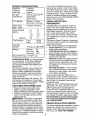
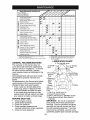
PRODUCT SPECIFICATIONS
i Gasoline 5 Gallons
Capacity Unleaded
and Type: Regular
iOil Type SAE 30 (above 32°F)
i (API-SF-SJ): SAE 5W-30
i' (below 32°F)
iOil Capacity: W/Filter 4.0 Pints
W/O Filter 3.75 Pints
Spark Plug: Champion QC12YC
',Gap: .040")
Ground Speed Lo: Hi:
(MPH): 0.7 1.7
1.4 3.3
2.3 5.4
Reverse: 0.9 2.1
Tire Pressure: Front: 14 PSI
Rear: 10 PSI
Charging
System: 16 Amps @ 3600 RPM
Battery: Amp/Hr: 35
Min. CCA: 280
Case size: UIR
Blade Bolt Torque: 27-35 Ft. Lbs.
CONGRATULATIONS on your purchase
of a new tractor. It has been designed,
engineered and manufactured to give
you the best possible dependability and
performance.
Should you experience any problem you
cannot easily remedy, please contact a
Sears or other qualified service center.
We have competent, well-trained techni-
cians and the proper tools to service or
repair this tractor.
Please read and retain this manual. The
instructions will enable you to assemble
and maintain your tractor properly. Always
observe the "SAFETY RULES".
CUSTOMER RESPONSIBILITIES
• Read and observe the safety rules.
• Follow a regular schedule in main-
taining, caring for and using your tractor.
• Follow the instructions under "Mainte-
nance" and "Storage" sections of this
owner's manual.
_I_WARNING: This tractor is equipped
with an internal combustion engine and
should not be used on or near any unim-
proved forest-covered, brush-covered or
grass-covered land unless the engine's
exhaust system is equipped with a spark
arrester meeting applicable local or state
laws (if any). If a spark arrester is used, it
should be maintained in effective working
order by the operator.
In the state of California the above is re-
quired by law (Section 4442 of the Califor-
nia Public Resources Code). Other states
may have similar laws. Federal laws apply
on federal lands. A spark arrester for the
muffler is available through your nearest
Sears service center (See REPAIR PARTS
section of this manual).
REPAIR PROTECTION
AGREEMENTS
Congratulations on making a smart pur-
chase. Your new Craftsman® product is
designed and manufactured for years of
dependable operation. But like all prod-
ucts, it may require repair from time to
time. That's when having a Repair Protec-
tion Agreement can save you money and
aggravation.
Purchase a Repair Protection Agreement
now and protect yourself from unexpected
hassle and expense.
Here's what's included in the Agreement:
• Expert service by our 12,000 profe-
sional repair specialists.
• Unlimited service and no charge for
parts and labor on all covered repairs.
• Product replacement if your covered
product can't be fixed.
• Discount of 10% from regular price of
service and service-related parts not
covered by the agreement; also, 10%
off regular price of preventive mainte-
nance check.
• Fast help by phone- phone support
from a Sears technician on products
requiring in-home repair, plus conve-
nient repair scheduling.
Once you purchase the Agreement, a
simple phone call is all that it takes for you
to schedule service. You can call anytime
day or night, or schedule a service ap-
pointment online.
Sears has over 12,000 professional repair
specialists, who have access to over 4.5
million quality parts and accessories.
That's the kind of professionalism you can
count on to help prolong the life of your
new purchase for years to come. Purchase
your Repair Protection Agreement today!
Some limitations and exclusions apply.
For prices and additional information
call 1-800-827-6655.
SEARS INSTALLATION SERVICE
For Sears professional installation of home
appliances, garage door openers, water
heaters, and other major home items, in
the U.S.A. call 1-800-4-MY-HOME®
6

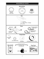
Steering
Wheel Insert
Steering Wheel
Seat
Steering Wheel
Adapter
(1) Washer
17/32 x 1-3/16 x 12 Gauge
_(1) Knob
(2) Flanged
_:Pins
(1) Front Plate
Assembly
(2) Shoulder
Bolts ©
(2) Centerlock Nuts
Mower
Gauge Wheels
(2) Wheels
(5) Retainer Springs
loop)
(2) Retainer Springs
, (single loop)
(2) Washers 3/8 x 3/4 x 14 Ga.
Video Cassette For Future Use
Keys
Slope Sheet
7

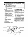
Your new tractor has been assembled at the factory with the exception of those parts left
unassembled for shipping purposes. To ensure safe and proper operation of your tractor
all parts and hardware you assemble must be tightened securely. Use the correct tools
as necessary to insure proper tightness. Review the video cassette before you begin.
TOOLS REQUIRED FOR ASSEMBLY
A socket wrench set will make assembly
easier. Standard wrench sizes you need
are listed below.
(1) 9/16"wrench (1) Pliers
(1) 1/2" wrench (1) Utility knife
(1) 3/4" socket with drive ratchet
(1) Tire pressure gauge
When right or left hand is mentioned in this
manual, it means, from your point of view,
when you are in the operating position
(seated behind the steering wheel).
TO REMOVE TRACTOR FROM
CARTON
UNPACK CARTON
1. Remove all accessible loose parts and
parts boxes from carton.
2. Cut along dotted lines on all four pan-
els of carton. Remove end panels and
lay side panels flat.
3. Remove mower and packing materials.
4. Check for any additional loose parts or
cartons and remove.
BEFORE REMOVING TRACTOR
FROM SKID
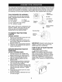
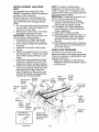
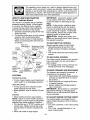
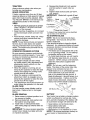
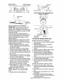
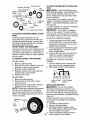
ATTACH STEERING WHEEL
1. Remove hex bolt, lock washer and
large flat washer from steering shaft.
2. Position front wheels of the tractor so
they are pointing straight forward.
3. Slide the steering sleeve over the
steering shaft.
4. Position steering wheel so cross bars
are horizontal (left to right) and slide
onto steering wheel adapter.
5. Secure steering wheel to steering shaft
with hex bolt, lock washer and large flat
washer previously removed. Tighten
securely.
6. Snap steering wheel insert into center
of steering wheel.
7. Remove protective materials from trac-
tor hood and grill.
Steering
Wheel Insert
ex Bolt
Lock Washer
Steering _ Large Flat
Wheel _ Washer
Steering Shaft
Steering
Sleeve
i Steering Wheel
Adapter
/
IMPORTANT: Check for and remove any
staples in skid that may puncture tires
where tractor is to roll off skid.
HOWTO SET UP YOUR TRACTOR
CHECK BATTERY
1. Lift hood to raised position.
NOTE: If this battery is put into service
after month and year indicated on label
(label located between terminals) charge
battery for minimum of one hour at 6-10
amps. (See "BATTERY" in Maintenance
section of this manual for charging instruc-
tions).
i
L
Label
8

INSTALLSEAT
Adjust seat before tightening adjustment
knob.
1. Remove adjustment knob and flat
washer securing seat to cardboard
packing and set aside for assembly of
seat to tractor.
2. Pivot seat upward and remove from
the cardboard packing. Remove the
cardboard packing and discard.
3. Place seat on seat pan so head of
shoulder bolts are positioned over the
large slotted holes in pan.
4. Push down on seat to engage shoulder
bolts in slots and pull seat towards rear
of tractor.
5. Pivot seat and pan forward and as-
semble adjustment knob and flat
washer loosely. Do not tighten.
6. Lower seat into operating position and
sit in seat.
7. Slide seat until a comfortable position
is reached which allows you to press
clutch/brake pedal all the way down.
8. Get off seat without moving its ad-
justed position.
9. Raise seat and tighten adjustment
knob securely.
Seat
Seat tn
Shoulder
Bolts
Adj
NOTE: You may now roll or drive your
tractor off the skid. Follow the appropriate
instruction below to remove the tractor
from the skid.
TO ROLLTRACTOR OFF SKID (See
Operation section for location and
function of controls)
1. Press lift lever plunger and raise
attachment lift lever to its highest po-
sition.
2. Release parking brake by depressing
clutch/brake pedal.
3. Place gearshift lever in neutral (N)
position.
4. Roll tractor forward off skid.
TO DRIVE TRACTOR OFF SKID (See
Operation section for location and
function of controls)
_iI,WARNING: Before starting, read, un-
derstand and follow all instructions in the
Operation section of this manual. Be sure
tractor is in a well-ventilated area. Be sure
the area in front of tractor is clear of other
people and objects.
1. Be sure all the above assembly steps
have been completed.
2. Check engine oil level and fill fuel tank
with gasoline.
3. Sit on seat in operating position,
depress clutch/brake pedal and set the
parking brake.
4. Place gear shift lever in neutral (N)
position.
5. Press lift lever plunger and raise
attachment lift lever to its highest posi-
tion.
6. Start the engine. After engine has
started, move throttle control to idle
position.
7. Depress clutch/brake pedal into full
"BRAKE" position and hold. Move
gearshift lever to 1st gear.
8. Slowly release clutch/brake pedal and
slowly drive tractor off skid.
9. Apply brake to stop tractor, set park-
ing brake and place gearshift lever in
neutral position.
10.Turn ignition key to "STOP" position.
Continue with the instructions that follow.
9

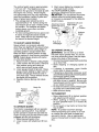
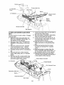
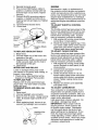
INSTALL MOWER AND DRIVE
BELT
See MOWER AND DRIVE BELT AS-
SEMBLY Supplement Sheet for additional
guidance on this assembly.
Be sure tractor is on level surface and
mower suspension arms are raised with
attachment lift control. Engage parking
brake.
1. Cut and remove ties securing anti-sway
bar and belts. Swing anti-sway bar to
left side of mower deck.
2. Slide mower under tractor with deflec-
tor shield to right side of tractor.
IMPORTANT: Check belt for proper rout-
ing in all mower pulley grooves.
3. If equipped, turn height adjustment
knob counterclockwise until it stops.
4. Lower mower linkage with attachment
lift control.
5. Install belt into electric clutch pulley
groove.
6. Place the suspension arms on inward
pointing deck pins. Retain with double
loop retainer spring with loops up as
shown.
7. Install front plate assembly to tractor
suspension brackets and retain with
single loop retainer springs as shown.
8. Position front plate assembly between
front mower brackets. Raise deck and
plate assembly to align holes and
insert flanged pins. Secure pins with
double loop retainer springs between
the plate and mower brackets.
Chassis
Double Loop Bracket
Retainer
Shoulder Gau,
Bolt Wheel
Front
Suspension Mower
Arms Bracket
Idler
NOTE: To assist in locating hole in
flanged pin, the hole in pin is inline with
notch on head of pin. If necessary, move
mower side-to-side to give space between
plate and mower brackets.
IMPORTANT: Check belt for proper rout-
ing in all mower pulley grooves.
9. Connect anti-sway bar to chassis
bracket under left footrest and retain
with double loop retainer spring.
10. If equipped, turn height adjustment
knob clockwise to remove slack from
mower suspension.
11. Raise deck to highest position.
12.Assemble gauge wheels as shown us-
ing long shoulder bolts, 3/8 washers,
and 3/8-16 center Iocknuts. Tighten
securely.
13.Adjust gauge wheels before operating
mower as shown in the Operation sec-
tion of this manual.
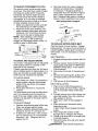
CHECKTIRE PRESSURE
The tires on your tractor were overin-
flated at the factory for shipping purposes.
Correct tire pressure is important for best
cutting performance.
•Reduce tire pressure to PSI shown in
"PRODUCT SPECIFICATIONS" section
of this manual.
Front Electric
Suspension Clutch
Brackets Pulley
Front Plate
_8
Washer
3/8-16 Double
Center Loop
Locknut Retainer
Spring
Use Pliers For
Retainer Springs
Bar
Double Loop
Retainer Spring
(Inward pointing
deck pins)
Single
Loop
Retainer
Springs
Deflector
Shield
Loop Down 10

CHECK MOWER LEVELNESS
For best cutting results, mower should
be properly leveled. See "TO LEVEL
MOWER HOUSING" in the Service and
Adjustments section of this manual.
CHECK FOR PROPER POSITION
OF ALL BELTS
See the figures that are shown for re-
placing motion, mower drive, and mower
blade drive belts in the Service and Ad-
justments section of this manual. Verify
that the belts are routed correctly.
CHECK BRAKESYSTEM
After you learn how to operate your trac-
tor, check to see that the brake is properly
adjusted. See "TO ADJUST BRAKE" in
the Service and Adjustments section of
this manual.
JCHECKLIST
Before you operate your new tractor, we
wish to assure that you receive the best
performance and satisfaction from this
Quality Product.
Please review the following checklist:
,/All assembly instructions have been
completed.
,/No remaining loose parts in carton.
,/Battery is properly prepared and
charged. (Minimum 1 hour at 6 amps).
,/Seat is adjusted comfortably and tight-
ened securely.
,/All tires are properly inflated. (For ship-
ping purposes, the tires were overin-
flated at the factory).
,/Be sure mower deck is properly leveled
side-to-side/front-to-rear for best cutting
results. (Tires must be properly inflated
for leveling).
,/Check mower and drive belts. Be sure
they are routed properly around pulleys
and inside all belt keepers.
,/Check wiring. See that all connections
are still secure and wires are properly
clamped.
While learning how to use your tractor, pay
extra attention to the following important
items:
,/Engine oil is at proper level.
,/Fuel tank is filled with fresh, clean, regu-
lar unleaded gasoline.
,/Become familiar with all controls, their
location and function. Operate them
before you start the engine.
,/Be sure brake system is in safe operat-
ing condition.
11

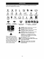
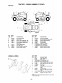
These symbols may appear on your tractor or in literature supplied with the product.
Learn and understand their meaning.
R N H L I',,I
REVERSE NEUTRAL NIGH LOW CHOKE FAST SLOW IGNITION
ENGINE OFF LIGHTS ON ENGINE ON ENGINE START PARKING BRAKE PARKING BRAKE PARKING BRAKE
LOCKED UNLOCKED
OVER TEMP FUEL OIL PRESSURE BATTERY REVERSE FORWARD
LIGHT MOWER HEIGHT MOWER LIFT
ATTACHMENT ATTACHMENT
CLUTCH ENGAGED CLUTCH DISENGAGED
FREE WHEEL
(Automatic Models only)
DANGER, KEEP HANDS
AND FEET AWAY
KEEP AREA CLEAR SLOPE HAZARDS
(SEE SAFETY RULES SECTION)
&
Failure to follow instructions
could result in serious injury or
death. The safety alert symbol
is used to identify safety inform-
ation about hazards which can
result in death, serious injury
and/or property damage.
&
&
&
DANGER indicatesa hazard which, if not avoided,
will result in death or serious injury.
WARNING indicatesa hazard which, if not avoided,
could result in death or serious injury.
CAUTION indicates a hazard which, ifnot avoided,
might result in minor or moderate injury.
CAUTION when used without the alert symbol,
indicates a situation that could result in damage
to the tractor and/or engine.
:_ HOT SURFACES indicatesa hazard which,
,dl_,., if not avoided, could result in death, serious injury
and/or property damage.
FIRE indicatesa hazard which, if not avoided,
could result in death, serious injury and/or
property damage.
12

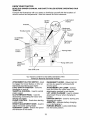
KNOW YOUR TRACTOR
READ THIS OWNER'S MANUAL AND SAFETY RULES BEFORE OPERATING YOUR
TRACTOR
Compare the illustrations with your tractor to familiarize yourself with the locations of
various controls and adjustments. Save this manual for future reference.
Ammeter
Ignition ht Switch
Switch Position
Throttle Control Clutch Switch
Lift Lever
Plunger
Clutch/Brake
Attachment
Lift Lever
Choke
Control Brake
Height
Adjustment
Knob
Gear Shift Lever
Range Shift Lever
\
Our tractors conform to the safety standards of the
American National Standards Institute.
ATTACHMENT CLUTCH SWITCH - Used
to engage the mower blades, or other at-
tachments mounted to your tractor.
LIGHT SWITCH POSITION - Turns the
headlights on and off.
THROTTLE CONTROL - Used to control
engine speed.
CLUTCH/BRAKE PEDAL - Used for
declutching and braking the tractor and
starting the engine.
CHOKE CONTROL - Used when starting
a cold engine.
HEIGHT ADJUSTMENT KNOB -Used to
adjust the mower cutting height.
GEARSHIFT LEVER - Selects the speed
and direction of the tractor.
RANGESHIFT LEVER - Allows high (H)
and low (L) speed for all forward and
reverse gears.
ATTACHMENT LIFT LEVER - Used to
raise and lower the mower deck or other
attachments mounted to your tractor.
LIFT LEVER PLUNGER - Used to release
attachment lift lever when changing its
position.
IGNITION SWITCH - Used for starting and
stopping the engine.
AMMETER - Indicates battery charging
(+) or discharging (-).
PARKING BRAKE - Locks clutch/brake
into the brake position.
13

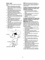
The operation of any tractor can result in foreign objects thrown into
the eyes, which can result in severe eye damage. Always wear safety
glasses or eye shields while operating your tractor or performing any
adjustments or repairs. We recommend standard safety glasses or a
wide vision safety mask worn over spectacles.
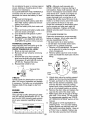
HOWTO USE YOUR TRACTOR
TO SET PARKING BRAKE
Your tractor is equipped with an operator
presence sensing switch. When engine
is running, any attempt by the operator
to leave the seat without first setting the
parking brake will shut off the engine.
1. Depress clutch/brake pedal all the way
down and hold.
2. Pull parking brake lever up and release
pressure from clutch/brake pedal.
Pedal should remain in brake position.
Make sure parking brake will hold trac-
tor secure.
Push-Into
"Disengaged"
Choke
Control
Throttle
Control
"Brake"
Attachment Clutch
Switch Pull Out To
"Engage"
Key
Brake
Clutch/ "Engaged"
Brake Pedal "Disengaged" Position
"Drive" . / Position Gear Shift
Position Height Adjustment Lever
Knob
STOPPING
MOWER BLADES -
• To stop mower blades, push attachment
clutch switch in to disengaged position.
GROUND DRIVE -
• To stop ground drive, depress clutch/
brake pedal all the way down.
• Move gearshift lever to neutral (N) posi-
tion.
ENGINE -
• Move throttle control to slow position.
NOTE: Failure to move throttle control to
slow position to allow engine to idle before
stopping may cause engine to "backfire".
• Turn ignition key to "STOP" position and
remove key. Always remove key when
leaving tractor to prevent unauthorized
use.
• Never use choke to stop engine.
IMPORTANT: Leaving the ignition switch
in any position other than "STOP" will
cause the battery to discharge and go
dead.
NOTE: Under certain conditions when
tractor is standing idle with the engine
running, hot engine exhaust gases may
cause "browning" of grass. To eliminate
this possibility, always stop engine when
stopping tractor on grass areas.
_CAUTION._ Always stop tractor com-
pletely, as described above, before leaving
the operator's position.
TO USE THROTTLE CONTROL
Always operate engine at full throttle.
• Operating engine at less than full
throttle reduces the battery charging
rate.
• Full throttle offers the best mower perfor-
mance.
TO USE CHOKE CONTROL
Use choke control whenever you are start-
ing a cold engine. Do not use to start a
warm engine.
• To engage choke control, pull knob out.
Slowly push knob in to disengage.
TO MOVE FORWARD AND BACKWARD
The direction and speed of movement is
controlled by the gearshift lever.
1. Start tractor with clutch/brake pedal de-
pressed and gearshift lever in neutral
(N) position.
2. Move gearshift and range shift levers
to desired position.
3. Slowly release clutch/brake pedal to
start movement.
IMPORTANT: Bring tractor to a complete
stop before shifting or changing gears.
Failure to do so will shorten the useful life
of your transaxle.
TO ADJUST MOWER CUTTING HEIGHT
The cutting height is controlled by turn-
ing the height adjustment knob in desired
direction.
•Turn knob clockwise (J_l) to raise cutting
height.
•Turn knob counterclockwise (v9 to
lower cutting height.
14

The cutting height range is approximately
1-1/2" to 4-1/2". The heights are mea-
sured from the ground to the blade tip with
the engine not running. These heights
are approximate and may vary depending
upon soil conditions, height of grass and
types of grass being mowed.
• The average lawn should be cut to
approximately 2-1/2 inches during the
cool season and to over 3 inches during
hot months. For healthier and better
looking lawns, mow often and after
moderate growth.
• For best cutting performance, grass over
6 inches in height should be mowed
twice. Make the first cut relatively high;
the second to desired height.
TO ADJUST GAUGE WHEELS
Gauge wheels are properly adjusted
when they are slightly off the ground when
mower is at the desired cutting height in
operating position. Gauge wheels then
keep the deck in proper position to help
prevent scalping in most terrain conditions.
NOTE: Adjust gauge wheels with tractor
on a flat level surface.
1. Adjust mower to desired cutting height.
2. Lower mower with lift control. Remove
rear retainer spring and clevis pin
which secure each gauge wheel.
3. Lower gauge wheels to ground. Raise
gauge wheels slightly to align holes in
bracket and gauge wheel bar and in-
sert clevis pins. Gauge wheels should
be slightly off the ground.
4. Replace retainer springs into clevis
pins.
Clevis Pin
Retainer
Spring _
Gauge _
Gauge / --_.
Wheel Bracket _
TO OPERATE MOWER
Your tractor is equipped with an operator
presence sensing switch. Any attempt
by the operator to leave the seat with the
engine running and the attachment clutch
engaged will shut off the engine.
1. Select desired height of cut.
2. Lower mower with attachment lift con-
trol.
3. Start mower blades by engaging at-
tachment clutch control.
TO STOP MOWER BLADES -
_JScengageattachment clutch control.
AUTION: Do not operate the mower
without either the entire grass catcher,
on mowers so equipped, or the deflector
shield in place. Attachment Lift Lever
_ttwatCchmpeL?_Ctu_tcTh High Positi/on Low
"Enga_ JJ/',-)'/Position
[ _ _I_"_/ _ _','_' Deflector
_- "_O_y \'_LJ \, :,'- Shield
D,s.." -'-?h
TO OPERATE ON HILLS
_i,WARNING: Do not drive up or down
hills with slopes greater than 15° and do
not drive across any slope. Use the slope
guide at the back of this manual.
• Choose the slowest speed before starting
up or down hills.
• Avoid stopping or changing speed on
hills.
• If slowing is necessary, move throttle
control lever to slower position.
• If stopping is absolutely necessary, push
clutch/brake pedal quickly to brake position
and engage parking brake.
• Move gearshift lever to 1st gear and range
shift lever to low (L) position. Be sure you
have allowed room for tractor to roll slightly
as you restart movement.
• To restart movement, slowly release park-
ing brake and clutch/brake pedal.
• Make all turns slowly.
TOTRANSPORT
• Raise attachment lift to highest position
with attachment lift control.
• When pushing or towing your tractor,
be sure gearshift lever is in neutral (N)
position.
• Do not push or tow tractor at more than
five (5) MPH.
NOTE: To protect hood from damage
when transporting your tractor on a truck
or a trailer, be sure hood is closed and
secured to tractor. Use an appropriate
means of tying hood to tractor (rope, cord,
etc.).
15

TOWING CARTS AND OTHER ATTACH-
MENTS
Tow only the attachments that are recom-
mended by and comply with specifications
of the manufacturer of your tractor. Use
common sense when towing. Too heavy
of a load, while on a slope, is dangerous.
Tires can lose traction with the ground and
cause you to lose control of your tractor.
BEFORE STARTING THE ENGINE
CHECK ENGINE OIL LEVEL
The engine in your tractor has been
shipped, from the factory, already filled
with summer weight oil.
1. Check engine oil with tractor on level
ground.
2. Remove oil fill cap/dipstick and wipe
clean, reinsert the dipstick and screw
cap tight, wait for a few seconds, re-
move and read oil level. If necessary,
add oil until "FULl" mark on dipstick is
reached. Do not overfill.
•For cold weather operation you should
change oil for easier starting (See the
oil viscosity chart in the Maintenance
section of this manual).
• To change engine oil, see the Mainte-
nance section in this manual.
ADD GASOLINE
• Fill fuel tank to bottom of filler neck. Do
not overfill. Use fresh, clean, regular
unleaded gasoline with a minimum of
87 octane. (Use of leaded gasoline will
increase carbon and lead oxide deposits
and reduce valve life). Do not mix oil
with gasoline. Purchase fuel in quan-
tities that can be used within 30 days to
assure fuel freshness.
_, CAUTION: Wipe off any spilled oil or
fuel. Do not store, spill or use gasoline
near an open flame.
IMPORTANT: When operating in temper-
atures below32°F(0°C), use fresh, clean
winter grade gasoline to help insure good
cold weather starting.
CAUTION: Alcohol blended fuels (called
gasohol or using ethanol or methanol) can
attract moisture which leads to separa-
tion and formation of acids during storage.
Acidic gas can damage the fuel system
of an engine while in storage. To avoid
engine problems, the fuel system should
be emptied before storage of 30 days
or longer. Drain the gas tank, start the
engine and let it run until the fuel lines
and carburetor are empty. Use fresh fuel
next season. See Storage Instructions for
additional information. Never use engine
or carburetor cleaner products in the fuel
tank or permanent damage may occur.
TO START ENGINE
When starting the engine for the first time
or if the engine has run out of fuel, it will
take extra cranking time to move fuel from
the tank to the engine.
1. Sit on seat in operating position,
depress clutch/brake pedal and set
parking brake.
2. Place gear shift lever in neutral (N)
position.
3. Move attachment clutch to disengaged
position.
4. Move throttle control to fast position
5. Pull choke control out for a cold engine
start attempt. For a warm engine start
attempt the choke control may not be
needed.
NOTE: Before starting, read the warm and
cold starting procedures below.
6. Insert key into ignition and turn key
clockwise to start position and release
key as soon as engine starts. Do
not run starter continuously for more
than fifteen seconds per minute. If the
engine does not start after several
attempts, push choke control in, wait
a few minutes and try again. If engine
still does not start, pull the choke con-
trol out and retry.
WARM WEATHER STARTING (50 ° F and
above)
7. When engine starts, slowly push choke
control in until the engine begins to
run smoothly. If the engine starts to
run roughly, pull the choke control out
slightly for a few seconds and then
continue to push the control in slowly.
16

• The attachments and ground drive can
now be used. If the engine does not
accept the load, restart the engine and
allow it to warm up for one minute using
the choke as described above.
COLD WEATHER STARTING (50° F and
below)
7. When engine starts, slowly push choke
control in until the engine begins to run
smoothly. Continue to push the choke
control in small steps allowing the en-
gine to accept small changes in speed
and load, until the choke control is fully
in. If the engine starts to run roughly,
pull the choke control out slightly for a
few seconds and then continue to push
the control in slowly. This may require
an engine warm-up period from several
seconds to several minutes, depending
on the temperature.
• The attachments can be used during
the engine warm-up period and may
require the choke control be pulled out
slightly.
NOTE: If at a high altitude (above 3000
feet) or in cold temperatures (below 32 F)
the carburetor fuel mixture may need to
be adjusted for best engine performance.
See "TO ADJUST CARBURETOR" in the
Service and Adjustments section of this
manual.
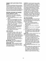
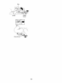
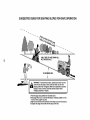
MOWING TIPS
• Tire chains cannot be used when the
mower housing is attached to tractor.
• Mower should be properly leveled for
best mowing performance. See "TO
LEVEL MOWER HOUSING" in the
Service and Adjustments section of this
manual.
• The left hand side of mower should be
used for trimming.
• Drive so that clippings are discharged
onto the area that has already been
cut. Have the cut area to the right of
the tractor. This will result in a more
even distribution of clippings and more
uniform cutting.
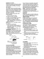
• When mowing large areas, start by
turning to the right so that clippings will
discharge away from shrubs, fences,
driveways, etc. After one or two rounds,
mow in the opposite direction making
left hand turns until finished.
f
1
f
f
C-J
• If grass is extremely tall, it should be
mowed twice to reduce load and pos-
sible fire hazard from dried clippings.
Make first cut relatively high; the second
to the desired height.
• Do not mow grass when it is wet.
Wet grass will plug mower and leave
undesirable clumps. Allow grass to dry
before mowing.
• Always operate engine at full throttle
when mowing to assure better mowing
performance and proper discharge of
material. Regulate ground speed by
selecting a low enough gear to give the
mower cutting performance as well as
the quality of cut desired.
• When operating attachments, select a
ground speed that will suit the terrain
and give best performance of the at-
tachment being used.
17

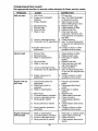
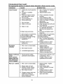
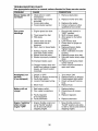
MAINTENANCE SCHEDULE ._*_ ,_ ,_-_ _ _. ,_/_
AS YOU COMPLETE
REGO RSERV,CE OATES
Chh:: kkTB_raek;,eOsPe_:i°n _
Check Operator Presence and
t Interlock Systems
R Check for Loose Fasteners
Sharpen/Replace Mower B_ades
t Lubrication Chart
0Check Battery Level
RC_ean Battery and Terminals
Check Transaxle Cooling
Check WBefts
Check Engine Oil Level
Change Engine Oil (with oil filter)
E Change Engine Oil (without oil filter)
N Clean Air Filter
(_ Clean Air Screen
Inspect Muffter/Spark Attester
E Replace Oil Filter (If equipped)
Clean Engine Cooling Fins
Replace Spark Plug
Replace Air Filter Paper Cartridge
Replace Fuel Filter
v'
v'
1 - Change more often when operating under a heavy load or
in high ambient temperatures.
2 _ Service more otten when operating in di_ty or dusty conditions.
3 - Replace blades more often when mowing in sandy soil
4 - Not required if equipped with maintenance-free battery.
5 - Tighten front axle pivot bolt to 35 ft.=tbs, maximum.
Do not ovedighten.
GENERAL RECOMMENDATIONS
The warranty on this tractor does not
cover items that have been subjected to
operator abuse or negligence. To receive
full value from the warranty, operator
must maintain tractor as instructed in this
manual.
Some adjustments will need to be made
periodically to properly maintain your
tractor.
All adjustments in the Service and Adjust-
ments section of this manual should be
checked at least once each season.
• Once a year you should replace the
spark plug, clean or replace air filter,
and check blades and belts for wear.
A new spark plug and clean air filter
assure proper air-fuel mixture and help
your engine run better and last longer.
BEFORE EACH USE
1. Check engine oil level.
2. Check brake operation.
3. Check tire pressure.
4. Check operator presence and
interlock systems for proper operation.
5. Check for loose fasteners.
LUBRICATION CHART
Ball Joints
@ -@ Spindle
Zerk Zerk
@Front Wheel @Front Wheel
Bearing Zerk
Zerk
@Steerin(
Sector
Gear
Teeth
_Check/ ® Engine
Add
Transaxle
Fluid
SAE 30 or 10w30 motor oil
@ General Purpose Grease
® Refer to Maintenance "ENGINE" Section
_) Spray silicone lubriant (Move Boots to
Lubricate)
IMPORTANT: Do not oil or grease the
pivot points which have special nylon
bearings. Viscous lubricants will attract
dust and dirt that will shorten the life of
the self-lubricating bearings. If you feel
they must be lubricated, use only a dry,
powdered graphite type lubricant sparingly.
18

TRACTOR
Always observe safety rules when per-
forming any maintenance.
BRAKE OPERATION
If tractor requires more than six (6) feet
stopping distance at high speed in highest
gear, then brake must be adjusted. (See
"TO ADJUST BRAKE" in the Service and
Adjustments section of this manual).
TIRES
• Maintain proper air pressure in all tires
(See "PRODUCT SPECIFICATIONS"
section of this manual).
• Keep tires free of gasoline, oil, or insect
control chemicals which can harm rub-
ber.
• Avoid stumps, stones, deep ruts, sharp
objects and other hazards that may
cause tire damage.
NOTE: To seal tire punctures and prevent
flat tires due to slow leaks, tire sealant
may be purchased from your local parts
dealer. Tire sealant also prevents tire dry
rot and corrosion.
OPERATOR PRESENCE SYSTEM
Be sure operator presence and interlock
systems are working properly. If your trac-
tor does not function as described, repair
the problem immediately.
• The engine should not start unless
the brake pedal is fully depressed and
attachement clutch control is in the
disengaged position.
• When the engine is running, any at-
tempt by the operator to leave the seat
without first setting the parking brake
should shut off the engine.
• When the engine is running and the
attachment clutch is engaged, any at-
tempt by the operator to leave the seat
should shut off the engine.
• The attachment clutch should never op-
erate unless the operator is in the seat.
BLADE CARE
For best results mower blades must be
kept sharp. Replace bent or damaged
blades.
BLADE REMOVAL
1. Raise mower to highest position to al-
low access to blades.
2. Remove blade bolt, lock washer and
flat washer securing blade.
3. Install new or resharpened blade
with trailing edge up towards deck as
shown.
IMPORTANT: To ensure proper assembly,
center hole in blade must align with star
on mandrel assembly.
4. Reassemble blade bolt, lock washer
and flat washer in exact order as
shown.
5. Tighten blade bolt securely (27-35 Ft.
Lbs. torque).
IMPORTANT: Blade bolt is grade 8 heat
treated.
k_-Blade Bolt
*A Grade 8 heat treated bolt can be identified
by six lines on the bolt head.
TO SHARPEN BLADE
NOTE: We do not recommend sharp-
ening blade - but if you do, be sure the
blade is balanced.
Care should be taken to keep the blade
balanced. An unbalanced blade will cause
excessive vibration and eventual damage
to mower and engine.
• The blade can be sharpened with a file
or on a grinding wheel. Do not attempt
to sharpen while on the mower.
• To check blade balance, you will need a
5/8" diameter steel bolt, pin, or a cone
balancer. (When using a cone balancer,
follow the instructions supplied with
balancer.)
NOTE: Do not use a nail for balancing
blade. The lobes of the center hole may
appear to be centered, but are not.
• Slide blade on to an unthreaded portion
of the steel bolt or pin and hold the
bolt or pin parallel with the ground. If
blade is balanced, it should remain in a
horizontal position. If either end of the
blade moves downward, sharpen the
heavy end until the blade is balanced.
Center Hole
BATTERY
Your tractor has a battery charging system
which is sufficient for normal use. How-
ever, periodic charging of the battery with
an automotive charger will extend its life.
• Keep battery and terminals clean.
• Keep battery bolts tight.
• Keep small vent holes open.
• Recharge at 6-10 amperes for 1 hour.
NOTE: The original equipment battery on
9Your tractor is maintenance free.
1

Donotattemptto openor removecaps or
covers.Addingorcheckinglevelofelec-
trolyteisnotnecessary.
TOCLEANBATTERYANDTERMINALS
Corrosionanddirt onthe batteryand
terminalscan causethe batteryto "leak"
power.
1. Removeterminalguard.
2. DisconnectBLACKbatterycablefirst
then RED batterycableandremove
batteryfromtractor.
3. Rinsethe batterywith plainwaterand
dry.
4. Cleanterminalsandbatterycableends
withwirebrushuntilbright.
5. Coatterminalswith greaseor petro-
leumjelly.
6. Reinstallbattery(See"REPLACING
BATTERY"inthe SERVICEANDAD-
JUSTMENTSsectionof thismanual).
TRANSAXLECOOLING
Keeptransaxlefreefrom build-upof dirt
and chaffwhichcan restrictcooling.
CHECKTRANSAXLEOIL LEVEL
1. Blockup rearaxle securely.
2. Removeleft rearwheelby removing
hubbolts.
3. Removefillerplugfromtransaxle. Oil
levelmustbe evenwith plugthreads.
Ifnecessary,fill with SAE30 motoroil,
APISF-SJ. Replacefillerplug.
4. Reassemblewheelto hub.
V-BELTS
Transaxle Filler
Plug
Check V-belts for deterioration and wear
after 100 hours of operation and replace
if necessary. The belts are not adjustable.
Replace belts if they begin to slip from
wear.
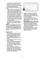
ENGINE
LUBRICATION
Only use high quality detergent oil rated
with API service classification SF-SJ. Se-
lect the oil's SAE viscosity grade accord-
ing to your expected operating tempera-
ture.
SAE VISCOSITY GRADES
8O
20
NOTE: Although multi-viscosity oils
(5W30, 10W30 etc.) improve starting in
cold weather, these multi-viscosity oils will
result in increased oil consumption when
used above 32°E Check your engine oil
level more frequently to avoid possible
engine damage from running low on oil.
Change the oil after every 50 hours of op-
eration or at least once a year if the tractor
is not used for 50 hours in one year.
Check the crankcase oil level before start-
ing the engine and after each eight (8)
hours of operation. Tighten oil fill cap/
dipstick securely each time you check the
oil level.
TO CHANGE ENGINE OIL
Determine temperature range expected
before oil change. All oil must meet API
service classification SF-SJ.
= Be sure tractor is on level surface.
= Oil will drain more freely when warm.
= Catch oil in a suitable container.
1. Remove oil fill cap/dipstick. Be careful
not to allow dirt to enter the engine
when changing oil.
2. Remove yellow cap from end of drain
valve and install the drain tube onto the
fitting. Oil Drain Valve
Yellow _
Cap'_ _ / C'°sed.J and
!_- Locked
Drain _ I I Position
Tube -
3. Unlock drain valve by pushing upward
slightly and turning counterclockwise.
4. To open, pull down on the drain valve.
5. After oil has drained completely, close
and lock the drain valve by pushing
upward and turning clockwise until the
pin is in the locked position as shown.
6. Remove the drain tube and replace the
cap onto the end of the drain valve.
7. Refill engine with oil through oil fill dip-
stick tube. Pour slowly. Do not overfill.
For approximate capacity see "PROD-
UCT SPECIFICATIONS" section of this
manual.
8. Use gauge on oil fill cap/dipstick for
checking level. For accurate reading,
tighten dipstick cap securely onto the
tube before removing dipstick. Keep oil
at "FULl.:' line on dipstick. Tighten cap
onto the tube securely when finished.
Page is loading ...
Page is loading ...
Page is loading ...
Page is loading ...
Page is loading ...
Page is loading ...
Page is loading ...
Page is loading ...
Page is loading ...
Page is loading ...
Page is loading ...
Page is loading ...
Page is loading ...
Page is loading ...
Page is loading ...
Page is loading ...
Page is loading ...
Page is loading ...
Page is loading ...
Page is loading ...
Page is loading ...
Page is loading ...
Page is loading ...
Page is loading ...
Page is loading ...
Page is loading ...
Page is loading ...
Page is loading ...
Page is loading ...
Page is loading ...
Page is loading ...
Page is loading ...
Page is loading ...
Page is loading ...
Page is loading ...
Page is loading ...
-
 1
1
-
 2
2
-
 3
3
-
 4
4
-
 5
5
-
 6
6
-
 7
7
-
 8
8
-
 9
9
-
 10
10
-
 11
11
-
 12
12
-
 13
13
-
 14
14
-
 15
15
-
 16
16
-
 17
17
-
 18
18
-
 19
19
-
 20
20
-
 21
21
-
 22
22
-
 23
23
-
 24
24
-
 25
25
-
 26
26
-
 27
27
-
 28
28
-
 29
29
-
 30
30
-
 31
31
-
 32
32
-
 33
33
-
 34
34
-
 35
35
-
 36
36
-
 37
37
-
 38
38
-
 39
39
-
 40
40
-
 41
41
-
 42
42
-
 43
43
-
 44
44
-
 45
45
-
 46
46
-
 47
47
-
 48
48
-
 49
49
-
 50
50
-
 51
51
-
 52
52
-
 53
53
-
 54
54
-
 55
55
-
 56
56


Craftsman 917.275970 Owner's manual
- Category
- Lawnmowers
- Type
- Owner's manual
- This manual is also suitable for
Ask a question and I''ll find the answer in the document
Finding information in a document is now easier with AI
Related papers
-
Craftsman 917.27632 User manual
-
-
-
-
-
-
-
-
-
Other documents
-
 Teraflex 2204000 Installation guide
-
 Hilmor 1839032 Operating instructions
-
Gibson 98023 User manual
-
 Bitspower BP-CMMK16-MBK Installation guide
-
Hotchkis 2236F Installation guide
-
Harold Beck & Sons 11-15X User manual
-
-
-
-
Stealth Products P91D274R3 User manual


