Sixnet Sixnet VT-MODEM-4 Installation guide

Type
Installation guide

This manual is also suitable for

Sixnet
®
Series
VT-MODEM-4
Hardware Guide | December 2018
Leased Line Industrial Modem
LP1087-A
©2018 Red Lion Controls, Inc. All rights reserved. Red Lion, the Red Lion logo and Sixnet are registered
trademarks of Red Lion Controls, Inc. All other company and product names are trademarks of their
respective owners.
Red Lion Controls, Inc.
20 Willow Springs Circle
York, PA 17406 USA
CONTACT INFORMATION:
Inside US: +1 (877) 432-9908
Outside US: +1 (717) 767-6511
Website: www.redlion.net
Revised 2018-12-10 Table of Contents
Drawing No. LP1087-A
i VT-MODEM-4
Hardware Guide
TableofContents
Preface
.............................................................................................. iii
Disclaimer ............... .......................................................................... iii
Purpose... ................................................ ................................ ........ iii
Audience .......... ................................................ ................................ iii
ComplianceStatements,Certifications &UserInformation ........................................ iii
FCCComplianceStatement ........
................................................................. iii
UserComplianceInformation .................................
............... ....................... iv
CanadianComplianceStatement.........
............... ............................................ iv
TrademarkAcknowledgments ................ ................................ ................ ......v
RegulatoryInformation.................................................... ................ .........v
ReleaseNotesandDocumentUpdates..............................................................v
PublicationHistory.......................................
..........................................v
RelatedDocuments.......
.........................................................................v
DocumentComments... .......................
............... .................................... vi
AdditionalProductInformation.................................................................... vi
SafetyInformation................................. ................................ ................ vi
Warnings/Cautions/Notes......................................................... ................ vi
HazardousLocationandInstallationRequirements................... ...
............... ................vii
AVERTISSEMENTSPOURINSTALLATIONETENDROITSDANGEREUX ......... .. ....
............... ..........vii
Chapter1ProductOverviewandHighlights .................................................1
ProductOverview..................................................................................1
ProductHighlights ..................................................................................1
VTMODEM4 .. ...............
....................................................................1
VTMODEM4FeaturesandBenefits.................... .......
............... ........................2
VTMODEM4Specifications .......................................................... ..............3
Chapter2 HardwareInstallation.................................. .. ................ ...........4
MountingtheVTMODEM4 ............... ................................................ .........4
ElectricalConnections......... ................ .. ................ .. .................................5
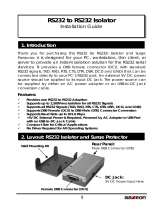
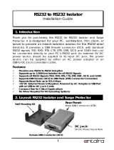
RS232Connections .....................
...........................................................5
IPmandSTGT1210RS232Connections....................................
...........................6
3rdPartyPLC/DeviceConnections .....................
...............................................7
VTMODEM4Power,
PhoneLineConnections ..........................................................8
DCPOWER ................................... .....
............... .............................8
Telep h oneCable ......
.........................................................................8
ModemConfiguration ..............................................................................9
VT-MODEM-4 Hardware Guide ii
Table of Contents Revised 2018-12-10
Drawing No. LP1087-A
ConfiguringaVTMODEM4 .........................................................................9
ATCommandStringAtPowerup ..................
...............................................9
ConfiguringaVTMODEM
4asanExternalModemonaPC.... ...........................................9
ModemInstallationinWindows®10.........................................
............... ......9
ModemInstallationinWindows®7................. ........
......................................9
ToRemoveaModem ..........
................................................................10
UsingaTermina lProgramtoConfiguretheVTMODEM4.............................
...............10
ConfiguringthePortParameters............ ................ .....
................................10
LeasedLineConnections ............................................................. .............13
TypesofLeasedLineconnections. ......................
.............................................13
MaintenanceInformation .......... ................................ .. ................ .............14
TroubleshootingTips ..........................
............... .....................................14
VTMODEMDefaultLEDIndications .................................. .. ..........
................14
ReconnectingSerialCables...................... .. ........
.....................................14
ResettingtheVTMODEM4..........
...........................................................14
ServiceandSupportInformation .................................. .............................16
ServiceInformation .................................................................. .............16
ProductSupport............................ .. ................ ................ .....................16
StatementofLimitedWarranty.......... .......................................................17
iii VT-MODEM-4 Hardware Guide
Revised 2018-12-10 Preface
Drawing No. LP1087-A
Preface
Disclaimer
Portions of this document are intended solely as an outline of methodologies to be followed during the
maintenance and operation of the VT-MODEM-4 equipment/software. It is not intended as a step-by-step guide or
a complete set of all procedures necessary and sufficient to complete all operations.
While every effort has been made to ensure that this document is complete and accurate at the time of release, the
information that it contains is subject to change. Red Lion Controls is not responsible for any additions to or
alterations of the original document. Industrial networks vary widely in their configurations, topologies, and traffic
conditions. This document is intended as a general guide only. It has not been tested for all possible applications,
and it may not be complete or accurate for some situations.
Users of this document are urged to heed warnings and cautions summarized at the front of the document, such as
electrical hazard warnings.
Purpose
This manual gives specific information on how to install and connect the VT-MODEM-4 to a PC.
Audience
The manual is intended for use by qualified personnel who are responsible for installing and maintaining network
equipment in an industrial environment.
ComplianceStatements,Certifications&UserInformation
FCCComplianceStatement
The Federal Communications Commission (FCC) has established rules which permit this device to be directly
connected to the telephone network. Standardized jacks are used for these connections. This equipment should
not be used on party lines or coin lines.
If this device is malfunctioning, it may also be causing harm to the telephone network; this device should be
disconnected until the source of the problem can be determined and until repair has been made. If this is not done,
the telephone company may temporarily disconnect service.
The telephone company may make changes in its technical operations and procedures; if such changes affect the
compatibility or use of this device, the telephone company is required to give adequate notice of the changes.
VT-MODEM-4 Hardware Guide iv
PREFACE REVISED 2018-12-10
D
RAWING NO. LP1087-A
If the telephone company requests information on what equipment is connected to their lines, inform them of:
The telephone number that it is connected to,
The Ringer Equivalence Number 0.3,
The USOC jack required RJ11, and
The FCC Registration Number 34579-MD-E
Items (b) and (d) are indicated on the label. The ringer equivalence number (REN) is used to determine how many
devices can be connected to your telephone line, In most areas, the sum of the RENs of all devices on any one line
should not exceed five (5.0). If too many devices are attached, they may not ring properly.
In the event of equipment malfunction, all repairs should be performed by our Company or authorized agent. It is the
responsibility of users requiring service to report the need for service to our company or one of our authorized agents.
UserComplianceInformation
If this equipment causes interference to radio or television reception, which can be determined by turning the
equipment off and on, the user is encouraged to try to correct the interference by one or more of the following
measures:
In order to meet FCC emissions limits, this equipment must be used only with cables that comply with IEEE 802.3.
If necessary, the user should consult the dealer or an experienced radio/television technician for additional
suggestions.
The user may find the following booklet prepared by the Federal Communications Commission helpful:
“How to Identify and Resolve Radio-TV Interference Problems”.
This booklet is available from: U.S. Government Printing Office, Washington DC, 20402 Stock No. 004-000-00345-4.
CanadianCompliance Statement
The VT-MODEM-4 meets the procedural and specification requirements for certification under the Terminal
Attachment Program.
Certification No.: 2991 8926 A
Issued To: Sixnet
Type Of Equipment: Multi-media Device
Trade Name And Model: VT-MODEM-4
Method Of Connection: CA11A
Ringer Equivalence No.: 0.3
v VT-MODEM-4 Hardware Guide
Revised 2018-12-10 Preface
Drawing No. LP1087-A
Certified To: Specification Cs03 Issue 8
Network Interface: LS
TrademarkAcknowledgments
Red Lion Controls acknowledges and recognizes ownership of the following trademarked terms used in this
document.
Microsoft
®
,
Windows
®
10, Windows
®
7, and Windows
®
are registered trademarks of the Microsoft
Corporation in the United States and/or other countries.
All other company and product names are trademarks of their respective owners.
RegulatoryInformation
FCC Part 15 and FCC Part 68; UL 508; CSA C22.2/142;
ACA TS 001- 1997; ACA TS 002-1997; AS/NZS3260-1993;
AS/NZS3548-1995; CTR21 (98/482/EC); EN55022; EIEC 950:1991;
Hazardous Locations: ANSI/ISA 12.12.01, CSA C22.2/213 (Class 1, Division 2 Groups A, B, C and D)
ReleaseNotesandDocumentUpdates
The hard copy and online versions of this document are revised only at major releases and, therefore, may not
always contain the latest product information. As needed, Tech Notes and or Product Bulletins will be provided
between major releases to describe any new information or document changes.
The latest online version of this document and all product updates can be accessed through the Red Lion web site
at w
ww.redlion.net/support/documentation
PublicationHistory
The following information lists the release history of this document.
RelatedDocuments
The following information lists available documents related to this product.
Issue/Revision Release Date Content Description
Revision A December 2018 Document updated to new format.
Initial Release August 2009 Original version.
VT-MODEM-4 Hardware Guide vi
PREFACE REVISED 2018-12-10
D
RAWING NO. LP1087-A
DocumentComments
Red Lion appreciates all comments that will help us to improve our documentation quality. The user can submit
comments through the Red Lion Customer Service. Simply email us at customer[email protected]
.
AdditionalProductInformation
Additional product information can be obtained by contacting the local sales representative or Red Lion through the
contact numbers and/or e-mail addresses listed on the back of the cover.
SafetyInformation
Warnings/Cautions/Notes
Warnings apply to situations where personal injury or death may result.
Mises en garde s'appliquent aux situations où les risques de blessures graves ou mortelles peuvent en résulter
Cautions apply where damage to equipment may result.
Les mises en garde s'appliquent dans le cas où les dommages matériels peuvent en résulter
Notes apply where additional noteworthy information, not in the general text flow but applicable, is made available
to the user.
Notes s'appliquent lorsque des informations dignes de mention, non pas dans l'enchaînement du texte mais il y a
lieu, est mis à la disposition de l'utilisateur
GeneralSafetyCautionsandWarnings/PrécautionsetAvertissementsdeSécuritéGénérale
Issue/Revision Release Date Document Title
LP1089 Revision A December 2018 VT-MODEM Industrial Modems Hardware Guide
LP1088 Revision A December 2018 VT-MODEM-5 Advanced 56K Modem Hardware Guide
WARNING – Must consult the guide in all cases where this symbol is marked.
AVERTISSEMENT – Doivent consulter le guide dans tous les cas où ce symbole est marqué.
vii VT-MODEM-4 Hardware Guide
Revised 2018-12-10 Preface
Drawing No. LP1087-A
HazardousLocationandInstallationRequirements
These products should not be used to replace proper safety interlocking. No software-based device (or any other
solid-state device) should ever be designed to be responsible for the maintenance of consequential equipment or
personnel safety. In particular, Red Lion disclaims any responsibility for damages, either direct or consequential,
that result from the use of this equipment in any application.
All power, input and output (I/O) wiring must be in accordance with Class I, Division 2 wiring methods and in
accordance with the authority having jurisdiction. Suitable for use in Class I, Division 2, Groups A, B, C and D
hazardous locations, or non-hazardous locations only.
AVERTISSEMENTSPOURINSTALLATIONETENDROITSDANGEREUX
Ces produits ne doivent pas être utilisés pour remplacer le verrouillage de sécurité approprié. Aucun dispositif
basé sur un logiciel (ou tout autre dispositif à l'état solide) devraient jamais être conçus pour être responsable de
l'entretien de l'équipement consécutifs ou la sécurité du personnel. En particulier, Red Lion décline toute
responsabilité pour les dommages, directs ou indirects, résultant de l'utilisation de cet équipement dans n'importe
quelle application.
Tout pouvoir, le câblage d'entrée et de sortie (I/O) doivent être conformes aux méthodes de câblage de Classe I,
Division 2 et conformément à l'autorité compétente. Cet équipement est adapté pour une utilisation en Classe1,
Division 2, Groupes A, B, C et D ou endroits non-dangereux
seulement.
CAUTION: If the equipment is used in the manner not specified by Red Lion, the protection
provided by the equipment may be impaired.
ATTENTION: Si l' équipement est utilisé d'une manière non spécifiée par Red Lion, la protection
fournie par l'équipement peut être compromise.
CAUTION: Do not operate the equipment in a manner not specified by this manual.
ATTENTION: Ne pas faire fonctionner l'équipement d'une manière non spécifiée par ce manuel.
WARNING: Install only in accordance with Local and National Codes of authorities having
jurisdiction.
AVERTISSEMENT: Installer uniquement, conformément aux codes locaux et nationaux des
autorités ayant compétence.
VT-MODEM-4 Hardware Guide viii
PREFACE REVISED 2018-12-10
D
RAWING NO. LP1087-A
WARNING: Explosion Hazard – Substitution of components may impair suitability for Class I,
Division 2.
AVERTISSEMENT - Risque d'explosion - La substitution de tout composant peut nuire à la
conformité de Classe 1, Division 2.
Warning – Do not remove or replace port connections while circuit is live unless the area is known
to be free of ignitible concentrations of flammable substances. For the required marking for the
port connections, instruction shall be included indicating that the marking shall be displayed on a
prominent place on the end-enclosure..
AvertissementNe pas retirer ou remplacer les connexions de port alors que le circuit est vivre à
moins que la région est connue pour être libre d'ignitible les concentrations de substances
inflammables. pour le marquage obligatoire pour les connexions de port, l'enseignement doit être
inclus en indiquant que le marquage doit être affichée sur une place de premier plan dans
l'enceinte.
WARNING – Explosion Hazard – Do not disconnect equipment unless power has been switched
off or the area is known to be non-hazardous.
AVERTISSEMENT - Risque d'explosion - Ne débranchez pas l’équipement à moins que l’ali-
mentation ait été coupée ou que l’environnement est connu pour être non dangereux.
WARNING - Never install or work on electrical equipment or cabling during periods of lightning
activity.
AVERTISSEMENT - Ne jamais installer ou travailler sur équipement électrique ou de câblage pen-
dant les périodes d'activité de la foudre.
CAUTION: Do not perform any services on the unit unless qualified to do so. Do not substitute
unauthorized parts or make unauthorized modifications to the unit.
ATTENTION: Ne pas effectuer de services sur l'appareil s'il n'est pas qualifié pour le faire. Ne pas
substituer pièces non autorisées ou de modifications non autorisées de l'appareil.
ix VT-MODEM-4 Hardware Guide
Revised 2018-12-10 Preface
Drawing No. LP1087-A
WARNING: Properly ground the unit before connecting anything else to the unit. Units not
properly grounded may result in a safety risk and could be hazardous and may void the warranty.
See the grounding technique section of this manual for proper ways to ground the unit.
AVERTISSEMENT: L'unité doit être correctement mise à la terre avant tout raccordement à l'unité.
Unités pas correctement mise à la terre peuvent causer un risque de sécurité et pourraient être
dangereuses et peuvent annuler la garantie. Voir la section technique de mise à la terre dans ce
mode d'emploi pour des moyens appropriés à la masse de l'appareil.
VT-MODEM-4 Hardware Guide 1-1
Product Overview and Highlights Revised 2018-12-10
Product Overview Drawing No. LP1087-A
Chapter1ProductOverviewandHighlights
1.1ProductOverview
The VT-MODEM-4 is a rugged industrial telephone modem that has been designed for operation in electrical
enclosures installed in harsh environments. The VT-MODEM-4 supports all standard Hayes AT commands, Fax
Class 1 and Class 2 commands and S-registers and therefore can be set-up as an external modem on any PC.
The VT-MODEM-4 is compatible with most telecommunications or dial-up networking software.
A VT-MODEM-4 allows easy access to PLCs, Sixnet
®
I/O and other devices via dial-in telephone connections or
leased line connections. The modem may be DIN rail or panel mounted for convenient and easy installation
adjacent to other DIN rail components inside of new or existing enclosures. Most Windows
®
software can
communicate through a VT-MODEM-4 to remote devices to perform file transfers, diagnostics, program debugging
and many other operations.
Use the VT-MODEM-4 in dial-up and leased line applications.
The Industrial Sixnet VT-MODEM-4 allows for remote access to 3rd Party devices.
1.2ProductHighlights
1.2.1VTMODEM4
Rated for -30° to +70°C operation
Proven in the toughest settings form pipelines in Alberta to remote locations in Sweden
DIN Rail or flat panel mounting
Supports all PLCs, RTUs and other devices
Compliant with telephone systems world-wide.
Revised 2018-12-10 Product Overview and Highlights
Drawing No. LP1087-A Product Highlights
1-2 VT-MODEM-4 Hardware Guide
1.2.2VTMODEM4FeaturesandBenefits
FEATURES AND BENEFITS
Rugged design for the toughest settings
-30° to 70°C operating temperature range
DIN Rail or flat panel mounting
Supports 2-wire leased line connections
Up to 33.6K
VT-MODEM-4 Hardware Guide 1-3
Product Overview and Highlights Revised 2018-12-10
VT-MODEM-4 Specifications Drawing No. LP1087-A
1.3VTMODEM4Specifications
TELEPHONE LINE
Max. Data Range 33600 bps (V.34)
Compatibility V.34 enhanced, V.34, V.32bis, V.32, V.22bis, V.22A/B, V.23, V.21, Bell212A & 103
Data Compression V.42 bis (4:1) and MNP 5 (2:1)
Error Correction V.42/MNP 3-4
Max. Fax Modem Rate 33.6 kbps
Fax Modem Compatibility ITU-T “Super” Group 3; Class 1.0, 2.0, 2.1; Group 3, Class 1 and 2, T.4, T.30, V.21,
V.27ter, V.29, V.34, V.17, and TIA/EIA TR29.2
Ringer Equivalent 0.3
Line Jack RJ11
Phone Jack RJ11
Transmit Level -11 dBm
Receiver Sensitivity -43 dBm under worst-case conditions
RS232 PORT
Max. RS232 Rate 115.2 kbps (Kilobaud)
RS232 Signal Support TXD, RXD, CTS, RTS, DCD, DTR, DSR, RI, GND
(Non- Flow Control Not Supported)
RS232 Connector DB9 female, RS232
Command Set All standard AT and S register commands including Class 1 and Class 2 Fax commands
STATUS LEDS
CD (Carrier detect) The modem has detected a carrier on the phone line (a remote modem has been
detected).
TR (Data Terminal Ready)
The PC (or Sixnet Station) has established a connection to the modem and is ready.
RD (Receive Data)
Flashes as data is received from the phone line.
TD (Transmit Data)
Flashes as data is sent out the phone line.
Power
On when power is present.
GENERAL CHARACTERISTICS
Input Power 10 - 30 VDC
Input Current 75mA @ 24VDC (typical)
52mA @ 24VDC (Sleep Inactivity Mode)
Certification FCC Part 15 and FCC Part 68; UL 508; CSA C22.2/142;
ACA TS 001- 1997; ACA TS 002-1997; AS/NZS3260-1993;
AS/NZS3548-1995; CTR21 (98/482/EC); EN55022; EIEC 950:1991;
Hazardous Locations: ANSI/ISA 12.12.01, CSA C22.2/213 (Class 1, Division 2 Groups
A, B, C and D)
Operating Temperature -30° to 70° C
Storage Temperature -40° to 85° C
Humidity 5 to 95% RH (non-condensing)
Mounting DIN rail or panel mount
Dimensions W x 4.75L x 1.35H inches (8.2 W x 12.1 L x 3.4H cm)
Revised 2018-12-10 Hardware Installation
Drawing No. LP1087-A Mounting the VT-MODEM-4
2-4 VT-MODEM-4 Hardware Guide
Chapter2 HardwareInstallation
2.1 Mounting the VT-MODEM-4
The VT-MODEM-4 snaps onto standard DIN rail (DIN EN 50022) or is mounted to a flat panel using #6 or #8
screws. See the image below. The modem can be installed in any orientation, directly adjacent to other DIN rail
components or in any convenient location within the enclosure. The modem should be installed within 6 feet of the
device it will be connected to.
For DIN rail mounting, hook the top, rear of the modem onto the top edge of the DIN rail. Using a small flathead
screwdriver, pull down on the spring-loaded tab on the bottom of the modem and push the modem back against the
rail. Reverse these steps to remove the modem. See the image below.
SIDE VIEW
FRONT VIEW
4.47" [11.35cm]
4.75" [12.07cm]
(clear for
#8 screw)
DIN
CD
TR
RD
TD
Power
VT-MODEM-2
SIXNET
Made in USA
Phone
Line
5 4 3 2 1
9 8 7 6
GND DTR TD RD DCD
RI CTS RTS DSR
1 2 3
0.25" [0.64cm]
0.28" [0.71cm]
3.17"
1.35"
+-
10-30 VDC
INDUSTRIAL MODEM
EN 50022
[8.05cm]
[3.44cm]
Ø0.17"
[Ø0.43]
2.92"
[7.42cm]
VT-MODEM-1,
DIN Rail (EN50022)
Insert screwdriver and pull down to release spring-loaded
tab Swing modem against rail and release
DIN Rail Mounting
VT-MODEM-4 Hardware Guide 2-5
Hardware Installation Revised 2018-12-10
Electrical Connections Drawing No. LP1087-A
2.2 Electrical Connections
2.2.1RS232Connections
Use the Sixnet
®
RS232 cable (VT-CABLE-MDM, which is 6 feet in length) or an equivalent cable to connect the
modem’s RS232 port (DB9 Male cable end) to the RS232 port on the SixTRAK
®
Gateway, VersaTRAK
®
RTU, or
PC (DB9 Female cable end). As shown in the image below, the VT-CABLE-MDM is a straight through serial
communications cable suitable for connecting a DTE device (PC, Gateway or VersaTRAK) to a DCE device (VT-
MODEM). For IPm
®
and ST-GT-1210 stations, use a straight-through Ethernet cable (not supplied) and the RJ45
to DB9 male adapter that comes with the station.
Cable requirements for PLCs and other devices may be different. Refer to the PLC or other device’s
documentation for cable pin-outs. Some PLC cables are documented in the Technical notes provided by Red Lion
technical support.
Note: The technical notes are not listed here.
Revised 2018-12-10 Hardware Installation
Drawing No. LP1087-A Electrical Connections
2-6 VT-MODEM-4 Hardware Guide
2.2.2IPmandSTGT1210RS232Connections
An un-wired DB9M to RJ45F adapter is provided for the RS232 port on the controller. The pin-outs follow the EIA/
TIA-561 standard (see the figure below). Use this adapter along with a RJ45 male to RJ45 male straight-thru wired
patch cable (not included) to make a connection between the VT-MODEM-4’s COM port (DB9 Female) and the
controllers RJ45 Female RS232 port. Enable hardware flow control in the IPm’s COM port configuration. Refer to
the Sixnet Electronic catalog for more information on connecting to other equipment.
TYPICAL MODEM ADAPTING WIRING
CABLE AND DB9M
SIXNET
RJ45F PIN #,
SIGNAL NAME
RJ45F TO DB9M
ADAPTER
WIRE COLOR
DB9 MALE CONNECTOR
PIN #,SIGNAL NAME
1 N/A Blue 9 RI out
2 N/A Orange 1 DCD out
3 N/A Black 4 DTR in
4GND Red 5 GND
5 RXD in Green 2 RXD out
6 TXD out Yellow 3 TXD in
7 CTS in Brown 8 CTS out
8 RTS out White 7 RTS in
5 4 3 2 1
9 8 7 6
“Pin Insertation” side of the DB9M
VT-MODEM-4 Hardware Guide 2-7
Hardware Installation Revised 2018-12-10
Electrical Connections Drawing No. LP1087-A
2.2.33rdPartyPLC/DeviceConnections
Determine if the device you are connecting to is a DTE or a DCE device. Use a straight-through cable to connect
the VT-MODEM to a DTE 3
rd
party device. A cross-wired cable must be used to connect the VT-MODEM to a DCE
3
rd
party device. If the 3
rd
party device does not support flow control pins 7 and 8 must be tied together.
Revised 2018-12-10 Hardware Installation
Drawing No. LP1087-A Electrical Connections
2-8 VT-MODEM-4 Hardware Guide
2.2.4VTMODEM4Power,PhoneLineConnections
2.2.4.1 DCPOWER
Connect 10 - 30 VDC to the VT-MODEM-4 as shown in the image in the section below. The modem can usually be
powered from the same DC source as other devices in the enclosure. All the screw terminals should be tightened to a
maximum of 3.48 in-lbs.
2.2.4.2 TelephoneCable
Connect analog phone lines to the RJ-11 jacks as appropriate. One RJ-11 jack is provided to connect directly to a
telephone (optional) and the second RJ-11 jack functions as the connection to the telephone network.
10-30 VDC
Input
INDUSTRIAL MODEM
Modem
RS232 Port
To Telephone
To Line
Pin
Signal
DCD out
RD out
TD in
DTR in
Sig GND
DSR out
RTS in
CTS out
RI out
1
2
3
4
5
6
7
8
9
CD
TR
RD
TD
Power
VT-MODEM SIXNET
Made in USA
Phone
Line
10-30 VDC
1 2 3
RI CTS RTS DSR
GND DTR TD RD DCD
5 4 3 2 1
9 8 7 6
VT-MODEM-4 Hardware Guide 2-9
Hardware Installation Revised 2018-12-10
Modem Configuration Drawing No. LP1087-A
2.3 Modem Configuration
2.3.1ConfiguringaVTMODEM4
All VT-MODEM models are factory configured to use the default communication settings for Sixnet
Stations. If a
VT-MODEM-4 is connected to a PLC, PC or other non-Sixnet device, then it may be necessary to reconfigure the
modem. To modify these parameters use the VT-MODEM Setup Wizard (v2.00 or later) located at
www.redlion.net/resources/software/sixnet-software/automation-devices-software-firmware
. The parameters can
also be modified using a Windows
®
terminal program.
2.3.1.1 ATCommandStringAtPowerup
Upon power-up, a Sixnet station can send a command string to a VT-MODEM-4. This capability can be used to
assure that the modem is set to a particular mode of operation, such as auto answer mode. Refer to the “Setting
Modem String” topic in the Sixnet I/O Tool Kit program’s online help for information on this capability. The Sixnet
Station can send any standard AT command.
2.3.2ConfiguringaVTMODEM4asanExternalModemonaPC
The VT-MODEM-4 can be connected directly to a PC. The modem will need to be installed in Windows prior to use.
Here are instructions to install the modem in most Windows Operating Systems.
2.3.2.1 ModemInstallationinWindows®10
1. Connect the DC power, communications cable (VT-CABLE-MDM or equivalent) and telephone line as
described above.
2. In the search box next to the Windows button type “Phone and Modem” and select the Phone and Modem in
Control Panel.
3. In the Modems tab, click the “Add” button. Do not select the “Don’t detect my modem, I will select it from a
list”. Instead, click Next and allow Windows to search the com ports and detect the modem.
4. Windows should find a modem called Standard Modem. Click Next and Windows will complete installation of
the Standard Modem. (Alternatively, click Change and select “Standard Modem Types” from the Manufactur-
ers list, and “Standard 28800 bps Modem” from the Models list.)
5. To verify that the modem has been installed, go to the “Phone and Modems” in Control Panel, then go to the
“modems” tab. The modem should be listed as either a “Standard Modem” or a “Standard 28800 bps Modem”
depending on the steps followed above.
6. Upon re-booting the machine, Windows may still find the VT-MODEM-4 as new hardware. If this happens,
select “Do not install a driver (Windows will not prompt again)”.
2.3.2.2 ModemInstallationinWindows®7
1. Select StartControl Panel, and then double click the Phone and Modems icon.
2. In the Modems tab, click the “Add” button. Do not select the “Don’t detect my modem, I will select it from a
list”. Instead, click Next and allow Windows to search the com ports and detect the modem.
3. Windows should find a modem called Standard Modem. Click Next and Windows will complete installation of
the Standard Modem. (Alternatively, click Change and select “Standard Modem Types” from the Manufactur-
ers list, and “Standard 28800 bps Modem” from the Models list.)
  • Page 1 1
  • Page 2 2
  • Page 3 3
  • Page 4 4
  • Page 5 5
  • Page 6 6
  • Page 7 7
  • Page 8 8
  • Page 9 9
  • Page 10 10
  • Page 11 11
  • Page 12 12
  • Page 13 13
  • Page 14 14
  • Page 15 15
  • Page 16 16
  • Page 17 17
  • Page 18 18
  • Page 19 19
  • Page 20 20
  • Page 21 21
  • Page 22 22
  • Page 23 23
  • Page 24 24
  • Page 25 25
  • Page 26 26
  • Page 27 27

Sixnet Sixnet VT-MODEM-4 Installation guide

Type
Installation guide
This manual is also suitable for

Ask a question and I''ll find the answer in the document

Finding information in a document is now easier with AI

in other languages