Page is loading ...

2704.1-082318
IMPORTANT: Read all instructions carefully before using this product. Retain
this owner’s manual for future reference. The specifications of this product
may vary from this photo, and, are subject to change without notice.
Sit-Up Bench


SERVICE--------------------------------------------------------------------
2
LABEL PLACEMENT-----------------------------------------------------
3
PRODUCT SAFETY------------------------------------------------------
4
ASSEMBLY PREPARATION--------------------------------------------
5
OVERVIEW------------------------------------------------------------------
6
HARDWARE PACK--------------------------------------------------------
7
PART LIST-------------------------------------------------------------------
8
STEP 1-----------------------------------------------------------------------
10
STEP 2-----------------------------------------------------------------------
12
STEP 3-----------------------------------------------------------------------
14
STEP 4-----------------------------------------------------------------------
16
STEP 5-----------------------------------------------------------------------
18
ADJUSTMENTS------------------------------------------------------------
20
WARRANTY-----------------------------------------------------------------
21
PART REQUEST FORM-------------------------------------------------
22
TABLE OF CONTENTS
1

IMPORTANT: FOR NORTH AMERICA ONLY
For a damaged or defective product, questions, replacement parts or any other service support, please
contact our customer service department by the below methods:
For The Best Service, please Email:
service@paradigmhw.com
Response Time: 1-2 Business Days
Emailing us with the information above will be the best method to receive a response during peak business
hours
Website:
www.paradigmhw.com
Toll-Free:
1-844-641-7920
(8:00 AM - 5:00 PM Pacific Standard Time, Monday thru Friday)
Response time may vary via calling
Please have the following information ready when requesting for service:
Your name
Phone number
Model number
Serial number
Part number
Proof of Purchase
For damaged or defective product please contact our customer service before returning to the store.
Paradigm Health & Wellness, Inc.
1189 Jellick Ave.
City of Industry, CA 91748, USA
SERVICE
2

LABEL PLACEMENT
3

WARNING: Before using this equipment you should consult with your personal physician to
see if the Sit-Up Bench is appropriate for you. Do not use this equipment without your
physician’s approval. Do not use this equipment if you have any of the following
conditions or ailments:
Extreme obesity
Glaucoma, retinal detachment or conjunctivitis
Pregnancy
Spinal injury, Cerebral Sclerosis, or acutely swollen joints
Middle ear infection
High blood pressure, hypertension, recent stroke or transient ischemic attack
Heart or circulatory disorders for which you are being treated
A hiatus hernia or a ventral hernia
Bone weaknesses including osteoporosis, unhealed fractures, modularly pins, or surgically
implanted orthopedic supports
Use of anticoagulants including Aspirin in high doses
The Maximum Weight Capacity for this product is 650lbs/295kgs.
Read all instructions carefully before assembling or operating this product. Retain this
owner’s manual, do not remove any safety labels from the machine and keep the original
purchase receipt for future reference.
This bench was designed and built for optimum safety. However, certain precautions apply
whenever you operate this exercise equipment. Be sure to read the entire manual before
assembling and operating this equipment. Also, please note the following safety instructions:
1. Consult your physician or other health care professionals before using the Sit-Up Bench.
2. Always wear proper exercise apparel when using this equipment. Use care when getting on or
off the unit.
3. If anytime you feel faint, light-headed, or dizziness while operating the equipment, stop
exercising immediately and contact your physician. You should also stop exercising if you
are experiencing pain or any kind of discomfort.
4. Keep children and pets away from this equipment at all times.
5. Only one person should use this equipment at a time.
6. Make sure your equipment is correctly assembled before you use it. Be sure all screws, nuts,
and bolts are tightened prior to use.
7. Do not operate this or any exercise equipment if it is damaged.
8. Wait 2 hours after eating before using this exercise equipment. If you get nauseous, stop
exercising as soon as you feel queasy.
9. Always use this equipment on a clear and level surface. Do not use outdoors or near water.
10. Keep hands and feet away from any moving parts. Do not insert any object into any
openings.
11. Keep loose clothes, jewelry, limbs and long hair away from moving parts.
12. Children under the age of 12 should not use this fitness equipment.
WARNING: CANCER AND REPRODUCTIV HARM--WWW.P65WARNINGS.CA.GOV.
PRODUCT SAFETY
4

Warning: It is highly recommended that you have assistance during the assembly of this
strength equipment.
1. Tools for assembly:
General tools needed for the assembly of this strength equipment:
Metric Allen Key Set
Metric Wrench Set and Adjustable Wrench
Flat Screwdrivers
Phillips Screwdrivers
Rubber Mallet
Silicone Spray Oil
2. Insert the bolts into the frame as illustrated in the drawing of each of the steps.
3. Hand-tighten the bolts, nuts, and screw during assembly. Hand-tightening will allow for easily
aligning the parts during assembly. Tighten all the hardware once the entire unit has been
completely assembled.
4. It is highly recommended that a professional installer assembles the strength equipment. But,
with the proper assistance, the right tools, strictly following the assembly steps, and given
enough time, the assembly of the unit can be achieved without professional help.
5. Thoroughly read each step before proceeding to assemble the items of that step.
6. To aid in assembly of the equipment, the hardware (bolts, nuts, washer…etc.) has been
presorted according to their corresponding steps. Each bag of hardware is labeled with its
corresponding step number.
7. When the equipment is fully assembled check all the functions for correct operation. Consult the
manual if you experience any issues, or for further help please contact our service department.
See page 2.
5
ASSEMBLY PREPARATION

OVERVIEW DRAWING
6

HARDWARE PACK
7

Part#
Description
Qty.
Part#
Description
Qty.
A
Main Frame
1
52
Flat Washer
D24*D13.5*D2.5T
14
B
Rear Stabilizer
1
54
Spring Washer
D15.4*D8.2*2T
10
C
Front Stabilizer
1
76
Nylon Nut
M12*1.75*12T
7
D
Supporting Tube
1
77
Nylon Nut
M8*1.25*8T
4
E
Adjusting Tube
1
180
Buffer 52*52*5T
1
F
Bed Frame
1
220
Inner Tube
60*60*50*50*197L
1
G
Seat Pad
1
221
Round Wheel
D70.5*23
2
H
Backrest
1
222
Foam
4
I
Headrest
1
223
Sleeve
4
J
Air Piston
1
270
Bushing
D29*D12.1*9T
6
3
Hex Bolt
M8*1.25*25L
10
271
Bushing
D22.2*D8.2*7T
4
8
Hex Bolt
M12*1.75*105L
6
301
Allen Screw
M3*0.5*4L
12
12
Allen Bolt
M8*1.25*45L
2
302
End Cap
D32*D26*24
5
50
Flat Washer
D18*D8.5*1.2T
10
303
Dip Foam
1
PART LIST
8

Part#
Description
Qty.
Part#
Description
Qty.
304
Fixing Ring
D32*D26*13
1
322
Hex Bolt
M8*1.25*75L
1
311
Buffer(1)
65*100*5T
4
323
Bushing D15*23.5L
2
316
Disk D60*D26.5*3T
4
328
Adjustable Pin
1
317
Roller Rod
2
329
Spring
D12*D1.0*56.5L
1
318
Hex Bolt
M12*1.75*95L
1
330
Nut
1
319
Hex Bolt
M8*1.25*65L
1
331
Round Knob
1
320
Bushing D15*18.5L
2
PART LIST
9

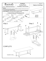
1A. Attach the Front Stabilizer (C) onto the Main Frame (A).Fasten the Front
Stabilizer (C) to the Main Frame (A) using:
2 - (8) Hex Bolt M12x1.75x105L
4 - (52) Flat Washer D24xD13.5x2.5T
2 - (76) Nylon Nut M12x1.75x12T
1B. Attach the Rear Stabilizer (B) onto the Main Frame (A).Fasten the Rear
Stabilizer (B) to the Main Frame (A) using:
2 - (8) Hex Bolt M12x1.75x105L
4 - (52) Flat Washer D24xD13.5x2.5T
2 - (76) Nylon Nut M12x1.75x12T
STEP 1
10

STEP 1
11
Open Wrench 13,19mm
2 PCS
NO.8 Hex Bolt
M12x1.75x105L
4PCS
NO. 76 Nylon Nut
M12x1.75x12T
4PCS
NO.52 Flat Washer
D24xD13.5xD2.5T
8PCS

2A. Insert Supporting Tube (D) into the bracket of Main Frame (A) and fasten
together using:
1 - (8) Hex Bolt M12x1.75x105L
2 - (52) Flat Washer D24xD13.5x2.5T
1 - (76) Nylon Nut M12x1.75x12T
STEP 2
12

STEP 2
13
NO.8 Hex Bolt
M12x1.75x105L
1PC
NO. 76 Nylon Nut
M12x1.75x12T
1PC
NO.52 Flat Washer
D24xD13.5xD2.5T
2PCS
Open Wrench 13,19mm
2 PCS

3A. Insert the front of the Bed Frame (F) into the bracket of Main Frame (A) using
1 - (8) Hex Bolt M12x1.75x105L
2 - (52) Flat Washer D24xD13.5x2.5T
1 - (76) Nylon Nut M12x1.75x12T
3B. Insert the free end of the Adjustable Tube (E) into the bracket under the Bed
Frame (F) using:
1 - (318) Hex Bolt M12x1.75x95L
2 - (52) Flat Washer D24xD13.5x2.5T
1 - (76) Nylon Nut M12x1.75x12T
3C. Now fully tighten the hardware installed on step 1, 2, and 3.
STEP 3
14

15
STEP 3
NO.8 Hex Bolt
M12x1.75x105L
1PC
NO. 76 Nylon Nut
M12x1.75x12T
2PCS
NO.52 Flat Washer
D24xD13.5xD2.5T
4PCS
NO.318 Hex Bolt
M12x1.75x95L
1PC
Open Wrench 13,19mm
2 PCS

4A. Attach the Headrest (I) onto the front of the Bed Frame (F) using:
2 - (3) Hex Bolt M8x1.25x25L
2 - (54) Spring Washer D15.4xD8.2x2T
2 - (50) Flat Washer D18xD8.5x1.2T
4B. Attach the Backrest (H) onto the middle of the Bed Frame (F) using:
4 - (3) Hex Bolt M8x1.25x25L
4 - (54) Spring Washer D15.4xD8.2x2T
4 - (50) Flat Washer D18xD8.5x1.2T
4C. Attach the Seat Pad (G) onto the middle of the Bed Frame (F) using:
4 - (3) Hex Bolt M8x1.25x25L
4 - (54) Spring Washer D15.4xD8.2x2T
4 - (50) Flat Washer D18xD8.5x1.2T
16
STEP 4

STEP 4
17
NO.3 Hex Bolt
M8x1.25x25L
10PCS
NO.54 Spring Washer
D15.4xD8.2x2T
10PCS
NO.50 Flat Washer
D18xD8.5x1.2T
10PCS
Open Wrench 13,19mm
1PC

5A. Insert and center the Roller Rods (317) into the Bed Frame (F). Slide the
Foam Rollers (222) with Sleeves (223) onto the ends of the Roller Rods (317).
Slide the Disks (316) onto the tips of the Roller Rods (317).
4 - (222) Foam Roller D23xD100x200L
4 - (223) Sleeve (ALREADY INSTALLED ON PART 222)
2 - (316) Disk D60xD26.5x3T
5B. Loosen the Allen Screws (301) in the End Cap (302) using the 1.5mm
Allen Wrench to slide the End Cap (302) onto Roller Rod (317). Position the
two Allen Screws (301) to fit into the two dimples on Roller Rods (317). Secure
the End Caps (302) by tightening the Allen Screws (301) using the 1.5mm
Allen Wrench.
2 - (302) End Cap D32xD26x24
4 - (301) Allen Screw M3x0.5x4L (ALREADY INSTALLED ON PART 302)
STEP 5
18
/