Makita LC1230 User manual

Category
Power universal cutters
Type
User manual

Makita LC1230 is a powerful 12-inch metal cutting saw designed for precise and efficient cutting of various metals. With its 1,300 RPM no-load speed and a sturdy base, it delivers clean and accurate cuts in materials like steel, aluminum, and pipes. The double insulation feature enhances user safety by preventing electric shock. It features a 305mm blade diameter and a maximum cutting capacity of 90mm x 85mm at a 90-degree angle and 45mm x 85mm at a 45-degree angle. It also has adjustable cutting angles, a safety cover, and a vise to securely hold the workpiece during operation.

Makita LC1230 is a powerful 12-inch metal cutting saw designed for precise and efficient cutting of various metals. With its 1,300 RPM no-load speed and a sturdy base, it delivers clean and accurate cuts in materials like steel, aluminum, and pipes. The double insulation feature enhances user safety by preventing electric shock. It features a 305mm blade diameter and a maximum cutting capacity of 90mm x 85mm at a 90-degree angle and 45mm x 85mm at a 45-degree angle. It also has adjustable cutting angles, a safety cover, and a vise to securely hold the workpiece during operation.

Metal Cutting Saw
305
mm
(12”)
MODEL
LC1230
INSTRUCTION MANUAL
DOUBLE
INSULATION
SPECIFICATIONS
Blade diameter
.............................................. ,305
mm
(1
2")
Hole
(arbor) diameter
..........................................
.25.4
mm
(1
"1
Noloadspeed(RPM)
.................................................
1,300
Dimensions
(L
x
W
x
H)
.........
516
mm
x
306
mm
603
mm
(20-1/3"
x
12"
x
23-W8")
Net weight
................................................
19.0
kg
(41.8
Ibs)
Cutting capacity
rB-I
AxB
t
_.
Cutting angle
45"
90
mm
(3-1/2")
85
mm
x
85
mm
(3-5/16"
x
3-5/16")
2
For
Your
Own
Safety
Read
Instruction
Manual
Before
Operating
Tool
Save
it
for
future reference
GENERAL SAFETY
PRECAUTIONS
(For
All
Tools)
1.
KNOW YOUR POWER TOOL. Read the owner's manual carefully. Learn the
tools applications and limitations, as well as the specific potential hazards
peculiar to
it.
2.
KEEP GUARDS IN PLACE and
in
working order.
3.
REMOVE ADJUSTING KEYS AND WRENCHES. Form habit of checking to
see that keys and adjusting wrenches are removed from tool before turning
it
on.
4.
KEEP WORK AREA CLEAN. Cluttered areas and benches invite accidents.
5.
DON'T USE IN DANGEROUS ENVIRONMENT. Don't use power tools
in
damp
or wet locations, or expose them to rain. Keep work area well lighted.
Don't use tool
in
presence of flammable liquids or gases.
6.
KEEP CHILDREN AWAY. All visitors should be kept safe distance from work
area.
7.
MAKE WORKSHOP KID
PROOF
with
padlocks, master switches, or by
removing starter keys.
8.
DON'T FORCE TOOL.
It
will do the job better and safer at the rate for which
it
was designed.
9.
USE RIGHT TOOL. Don't force tool or attachment to do a job for which
it
was not designed.
IO.
WEAR PROPER APPAREL. Do not wear loose clothing, gloves, neckties, rings,
bracelets, or other jewelry which may get caught
in
moving parts. Nonslip
footwear is recommended. Wear protective hair covering to contain long hair.
11.
ALWAYS USE SAFETY GLASSES. Also use face or dust mask
if
cutting
operation is dusty. Everyday eyeglasses only have impact resistant lenses,
they are NOT safety glasses.
12.
SECURE WORK. Use clamps or a vise to hold work when practical. It's safer
than using your hand and
it
frees both hands to operate tool.
13.
DON'T OVERREACH. Keep proper footing and balance at all times.
14.
MAINTAIN TOOLS WITH CARE. Keep tools sharp and clean for best and
safest performance. Follow instructions for lubricating and changing acces-
sories.
3
Ampere Rating
More Than More Than
Not
Volts
I
Total
length of cord in feet
120
V
I
25
ft.
50
ft.
100
ft.
150
ft.
AWG
4
0
6
6
10
10 12
12 16
18 16 16 14
18 16 14 12
16 16 14 12
14 12
Not Recommended
VOLTAGE WARNING: Before connecting the tool
to
a
power source (receptacle,
outlet, etc.) be sure the voltage supplied is the same as that specified
on
the
nameplate of the tool. A power source with voltage greater than that specified
for the tool can result
in
SERIOUS INJURY to the user
-
as well as damage to
the tool. If in doubt, DO NOT PLUG IN THE TOOL. Using a power source with
voltage less than the nameplate rating is harmful to the motor.
ADDITIONAL
SAFETY
RULES
1.
Wear eye protection.
2.
Do not operate saw without guards
in
place.
3.
Don't use the tool
in
the presence of flammable liquids
or
gases.
4.
Check the blade carefully for cracks
or
damage before operation.
5.
Use only flanges specified for this tool.
6.
Be careful not to damage the arbor, flanges (especially the installing surface)
7. Make sure that the base is properly secured
so
it
will not move during
8.
For
your safety, remove the chips, small pieces, etc. from the table top before
9.
Make sure the shaft lock is released before the switch is turned on.
Replace cracked or damaged blade immediately.
or bolt. Damage to these parts could result in blade breakage.
operation.
operation.
IO.
Be sure that the blade does not contact the base
in
the lowest position.
11.
Hold the handle firmly. Be aware that the saw moves up or down slightly
during start-up and stopping.
12.
Do
not perform any operation freehand. The workpiece must be secured
firmly with the vise during all operations.
13.
Keep hands out of path of saw blade, Avoid contact with any coasting blade.
It
can still cause severe injury.
14.
Never reach around saw blade.
15.
Make sure the blade is not contacting the workpiece before the switch is
turned on.
16.
Before using the tool on an actual workpiece, let
it
run for a while. Watch
for vibration or wobbling that could indicate poor installation or a poorly
balanced blade.
17. Wait until the blade attains
full
speed before cutting.
18. Stop operation immediately
if
you notice anything abnormal.
19.
DO
not attempt to lock the trigger in the on position.
20.
Shut off power and wait for saw blade to stop before servicing or adjusting
tool.
5
Socket
wrench
The socket wrench is stored on the left
side
of
the tool base. When using the
socket wrench, pull it out
of
the wrench
holder. After using the socket wrench,
return it to the wrench holder.
Positioning the
tool
When the tool is shipped from the factory,
the handle is locked in the lowered posi-
tion. Release the handle from the lowered
position by lowering is slightly and remov-
ing the chain from the hook on the handle.
Bolt the tool with two bolts to
a
level and
stable surface using the bolt holes provided
in the
tool
base. This will help prevent tip-
ping and possible injury.
Bolt
-
U
7
Removing
or
installing
saw
blade
CAUTION:
.Always be sure that the tool is switched off and unplugged before removing or installing
the blade.
.When mounting the blade, make sure that the direction
of
the arrow on the surface of
the blade matches the direction of the arrow on the blade case.
.Use only the Makita socket wrench provided to install or remove the blade. Failure to do
so
may result in overtightening or insufficient tightening of the hex bolt. This could cause
serious injury to operator or others in the general vicinity of the tool.
.Do
not touch the blade immediately after operation; it may be extremely hot and could
burn your skin.
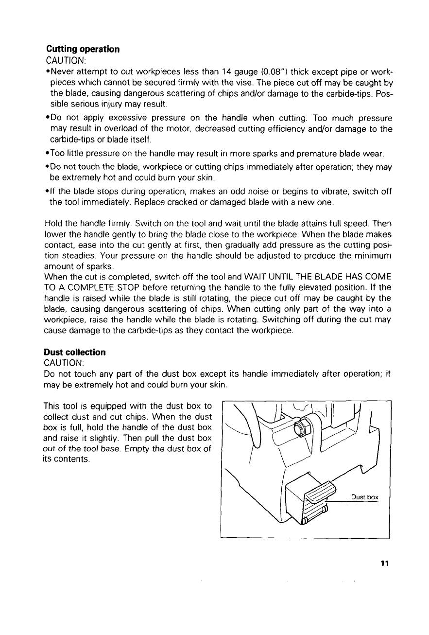
To
remove the blade, loosen the hex bolt
holding the center cover with the socket
wrench. Raise the safety cover (safety
guard) and center cover.
Center cover
Hex
bolt
Safety
cover
1
Socket wrench
Press the shaft lock to lock the spindle and
use the socket wrench to loosen the hex
bolt by turning counterclockwise. Then
remove the hex bolt, outer flange and
blade.
8
To install the blade, mount the inner flange,
saw blade, outer flange and hex bolt onto
the spindle in that order. Tighten the hex
bolt by turning clockwise while pressing the
shaft lock. Return the safety cover and
center cover to the original position. Then
tighten the hex bolt clockwise to secure the
center cover. Lower the handle to make
sure that the safety cover moves properly.
Carbide-tipped saw blade Hex bolt
I
I7
Setting for desired cutting angle
CAUTION:
Always tighten the hex bolt securely after changing the cutting angle.
To change the cutting angle, loosen the
lever. Move the vise stop
so
that the indi-
cator
will
point to the desired graduation.
Then tighten the lever to secure the vise
stop.
Graduation Indicator
Securing workpieces
CAUTION:
Always set the vise nut to the right fully when securing the workpiece. Failure to do
so
may result in insufficient securing of the workpiece. This could cause the workpiece to be
ejected or cause damage to the blade.
By
turning the vise handle counterclock-
wise and then flipping the vise nut to the
left, the vise is released from the shaft
threads and can be moved rapidly in and
out. To grip workpieces, push the vise
handle until the vise plate contacts the
workpiece. Flip the vise nut to the right and
then turn the vise handle clockwise to
securely retain the workpiece.
Vise plate Vise nut
I
9
Long workpieces must be supported by
blocks of non-flammable material on either
side
so
that it will be level with the base
top.
To
prevent the trigger from being acciden-
When cutting angles or channels, secure them as shown in the figure below.
I
0 0 0
L
L
L
Angle
Channel
Switch
action
CAUTION:
Before plugging in the tool, always check to see that the switch trigger actuates properly
10
Carrying the tool
Fold down the tool head to the position
where you can attach the chain to the hook
on the handle. Grasp the carrying grip
when carrying the tool.
I
Ill
MAINTENANCE
CAUTION:
Always be sure that the tool is switched off and unplugged before attempting to perform
inspection or maintenance.
Replacing saw blade
Continuing to use
a
dull and worn blade may cause motor overload and decreased cutting
efficiency. Replace with
a
new blade as soon as it is no longer effective.
Replacing carbon brushes
Remove and check the carbon brushes
regularly. Replace when they wear down
to
the limit mark. Keep the carbon brushes
clean and free to slip in the holders. Both
carbon brushes should be replaced at
the same time. Use only identical carbon
brushes.
Use
a
screwdriver to remove the brush
holder caps. Take out the worn carbon
brushes, insert the new ones and secure
the brush holder caps.
/
Limit mark
To maintain product SAFETY and
RELIABILITY,
repairs, maintenance or adjustment should
be performed by Makita Authorized or Factory Service Centers, always using Makita
replacement parts.
12
ACCESSORIES
CAUTION
These accessories or attachments are recommended for use
with
your Makita tool specified in thls
manual The use
of
any other accessories or attachments might present
a
risk
of
injury to persons
The accessories or attachments should be used
only
in
the proper and intended manner.
*Carbide-tipped saw blade
305
mm
(12”)
Carbide-tipped saw blade
&
workpiece ranges
(NA
Not
applicable
CAUTION:
Always use carbide-tipped saw blades appropriate for your job.
Do
not cut aluminum, wood, plastics, concrete, tiles, etc
Carbide-tipped saw blades for metal cutting saw are not to be re-sharpened.
13
June-7-’99
US
305
mm
(12”)
METAL CUTTING SAW
Model LC1230
14
114
Note: The switch and other part configurations
may differ from country
to
country.
15
"."D.l
P..
6
Mf.4
MAKITA LIMITED ONE YEAR WARRANTY
Warranty
Policy
Every Makita tool is thoroughly inspected and tested before leaving the factory. It
IS
warranted to
be free
of
defects from workmanship and materials for the period of ONE YEAR from the date
of
original purchase. Should any trouble develop during this one-year period, return the COMPLETE
tool, freight prepaid, to one of Makita's Factory
or
Authorized Service Centers. If inspection shows
the trouble is caused by defective workmanship
or
material. Makita
will
repair
(or
at
our
option,
replace) without charge.
This
Warranty does not apply where:
repairs have been made or attempted by others:
repairs are required because of
normal
wear
and
tear
The
tool
has been abused, misused
or
improperly maintained,
alterations have been made to the tool.
IN NO EVENT SHALL MAKITA BE LIABLE FOR ANY INDIRECT. INCIDLNTAL
OR
CON-
SEQUENTIAL DAMAGES FROM THE SALE
OR
USE OF THt PRODUCT. THIS DlSCLAlMhR
APPLIES BOTH DURING AND AFTER THE TERM OF THIS WARRANTY.
MAKITA DISCLAIMS LIABILITY FOR ANY IMPLIED WARRANTltS, INCLUDING IMPLED
WARRANTIES OF "MERCHANTABILITY" AND "FITNESS FOR A SPECIFIC PURPOSE,"
AFTER THE ONE-YEAR TERM OF THIS WARRANTY.
~~
This Warranty
gives
you specific
legal
rights, and you may
also
have other nghts which vary from
state
to
state. Some stater do not allow the exclusion
or
limitation of incidental
or
consequential
damages.
so
the above limitation
or
exclusion may not apply
to
you. Some states do not allow
limitation
on
haw
long an implied warranty lasts,
so
the above hitatton may not apply to you.
J
Makita Corporation
884227~983
3-11
-8,
Sumiyoshi-cho,
Anjo,
Aichi
446-8502
Japan
PRINTED
IN
JAPAN
1999-1
0-N
  • Page 1 1
  • Page 2 2
  • Page 3 3
  • Page 4 4
  • Page 5 5
  • Page 6 6
  • Page 7 7
  • Page 8 8
  • Page 9 9
  • Page 10 10
  • Page 11 11
  • Page 12 12
  • Page 13 13
  • Page 14 14
  • Page 15 15
  • Page 16 16

Makita LC1230 User manual

Category
Power universal cutters
Type
User manual

Makita LC1230 is a powerful 12-inch metal cutting saw designed for precise and efficient cutting of various metals. With its 1,300 RPM no-load speed and a sturdy base, it delivers clean and accurate cuts in materials like steel, aluminum, and pipes. The double insulation feature enhances user safety by preventing electric shock. It features a 305mm blade diameter and a maximum cutting capacity of 90mm x 85mm at a 90-degree angle and 45mm x 85mm at a 45-degree angle. It also has adjustable cutting angles, a safety cover, and a vise to securely hold the workpiece during operation.

Ask a question and I''ll find the answer in the document

Finding information in a document is now easier with AI