Black & Decker TL10 User manual
- Category
- Mini tillers
- Type
- User manual

Garden Tiller
INSTRUCTION MANUAL
Date Code:
Catalog Number
TL10
INSTRUCTIVO DE OPERACIÓN, CENTROS DE SERVICIO Y PÓLIZA DE GARANTÍA.
ADVERTENCIA: LÉASE ESTE INSTRUCTIVO ANTES DE USAR EL PRODUCTO.
VEA EL ESPAÑOL EN LA CONTRAPORTADA.
SAVE THIS INSTRUCTION MANUAL FOR FUTURE REFERENCE.
Thank you for choosing Black & Decker! Go to
www.BlackandDecker.com/NewOwner to register your new product.
PLEASE READ BEFORE RETURNING THIS PRODUCT FOR ANY REASON:
If you have a question or experience a problem with your Black & Decker purchase, go to
WWW.BLACKANDDECKER.COM/INSTANTANSWERS for instant answers 24 hours a day.
If you canʼt find the answer or do not have access to the internet,
call 1-800-544-6986 from 8 a.m. to 5 p.m. EST Mon. - Fri. to speak with an agent.
Please have the catalog number available when you call.

TABLE OF CONTENTS
Safety Guidelines - Definitions.......................................................................2
Important Safety Instructions .........................................................................3
Extension Cords.............................................................................................4
Functional Description ...................................................................................5
Assembly Instructions ....................................................................................6
Unpacking ...................................................................................................6
Mid Handle Assembly .................................................................................6
Upper Handle Assembly .............................................................................6
Wheel Assembly..........................................................................................7
Tine Assembly.............................................................................................7
Drag Bar Assembly .....................................................................................7
Operating Instructions....................................................................................8
Ballast Tank.................................................................................................8
Attaching Extension Cord............................................................................8
Switch Use ..................................................................................................8
Adjusting the Drag Bar ................................................................................9
Using the Tiller ............................................................................................9
Troubleshooting .............................................................................................10
Maintenance ..................................................................................................10
Storage...........................................................................................................10
Accessories....................................................................................................10
Service Information ........................................................................................10
Warranty.........................................................................................................11
SAFETY GUIDELINES - DEFINITIONS
It is important for you to read and understand this manual. The information it contains relates to protecting YOUR
SAFETY and PREVENTING PROBLEMS. The symbols below are used to help you recognize this information.
DANGER: Indicates an imminently hazardous situation which, if not avoided, will result in death or serious injury.
WARNING: Indicates a potentially hazardous situation which, if not avoided, could result in death or serious
injury.
CAUTION: Indicates a potentially haz ard ous situation which, if not avoided, may result in minor or mod er ate
injury.
NOTICE: Used without the safety alert symbol indicates a potentially hazardous situation which, if not avoided, may
result in property damage.
2

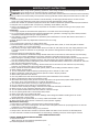
IMPORTANT SAFETY INSTRUCTIONS
DANGER:
When using electric gardening appliances, basic safety precautions should always be followed to
reduce the risk of fire, electric shock, and personal injury, including the following:
DANGER: When using the unit, you must follow the safety rules. Please read these instructions before operating
the unit in order to ensure the safety of the operator and any bystanders. Please keep these instructions for later use.
Training
1. Read the operating and service instruction manual carefully. Be thoroughly familiar with the controls and the
proper use of the equipment. Know how to stop the unit and disengage the controls quickly.
2. Never allow children to operate the equipment. Never allow adults to operate the equipment without proper instruction.
3. Keep the area of operation clear of all persons, particularly small children, and pets.
4. Keep in mind that the operator or user is responsible for accidents or hazards occurring to other people, their
property, and themselves.
Preparation
1. Thoroughly inspect the area where the equipment is to be used and remove all foreign objects.
2. Do not operate the equipment without wearing adequate outer garments, including long pants. Wear protective
footwear that will improve footing on slippery surfaces.
3. Use extension cords and receptacles as specified by the manufacturer for all units with electric drive motors or
electric starting motors.
4. Never attempt to make any adjustments while the motor is running.
Operation
1. Do not put hands or feet near or under rotating parts.
2. Exercise extreme caution when operating on or crossing gravel drives, walks, or roads. Stay alert for hidden
hazards or traffic. Do not carry passengers.
3. After striking a foreign object, release switch lever to turn tiller off, wait until tines stop and unplug extension cord.
Thoroughly inspect the machine for any damage, and repair the damage before restarting and operating the
machine.
4. Exercise caution to avoid slipping or falling.
5. If the unit should start to vibrate abnormally, release switch lever to turn tiller off, wait until tines stop and unplug
extension cord. Check immediately for the cause. Vibration is generally a warning sign of trouble.
6. When leaving the operating position, release switch lever to turn tiller off, wait until tines stop and unplug extension
cord, This includes before unclogging the tines, and when making any repairs, adjustments, and inspections.
7. Take all possible precautions when leaving the machine unattended. Release switch lever to turn tiller off, wait until
tines stop and unplug extension cord.
8. Before cleaning, repairing, or inspecting, release switch lever to turn tiller off, wait until tines stop and unplug
extension cord. Make certain all moving parts have stopped.
9. Never operate the machine without proper guards, plates, or other safety protective devices in place.
10. Keep children and pets away.
11. Do not overload the machine capacity by attempting to till too deep at too fast a rate.
12. Never operate the machine at high transport speeds on hard or slippery surfaces.
13. Never allow bystanders near the unit.
14. Use only attachments and accessories approved by the manufacturer of the machine.
15. Never operate the tiller without good visibility or light.
16. Be careful when tilling in hard ground. The tines may catch in the ground and propel the tiller forward, If
this occurs, let go of the handle and do not restrain the machine.
17. Use extreme caution when reversing or pulling the machine towards you.
18. Do not change the motor settings or overspeed the motor.
19. Start the motor carefully according to instructions and with feet well away from the tines.
20. Never pick up or carry a machine while the motor is running.
21. Do not operate the tiller while under the influence of alcohol or drugs.
22. Do not operate garden tiller on excessively steep slopes.
23. Keep a firm hold on the handle at all times.
24. Use caution when cultivating near fences, buildings and underground utilities. Rotating tines can cause
property damage or person injury.
25. When picking up the garden tiller, do not lift by ballast tank handle or latch.
26. Never tamper with safety devices. Check their proper operation regularly.
Maintenance and Storage
1. Keep machine, attachments, and accessories in safe working condition.
2. Check shear bolts, motor mounting bolts, and other bolts at frequent intervals for proper tightness to be sure the
equipment is in safe working condition.
3. Allow the motor to cool before storing in any enclosure.
4. Always refer to the instruction manual for important details if the tiller is to be stored for an extended period.
5. Follow instruction manual recommendations for safe loading, unloading, transport, and storage of machine.
SAVE THESE INSTRUCTIONS
FOR ALL DOUBLE-INSULATED APPLIANCES
1) Replacement Parts
When servicing use only identical replacement parts.
2) Polarized Appliance Connections
3

To reduce the risk of electric shock, this appliance has a polarized plug (one blade is wider than the other) and will
require the use of a polarized extension cord. The appliance plug will fit into a polarized extension cord only one
way. If the plug does not fit fully into the extension cord, reverse the plug. If the plug still does not fit, obtain a correct
polarized extension cord. A polarized extension cord will require the use of a polarized wall outlet. The plug will fit
into the polarized wall outlet only one way. If the plug does not fit fully into the wall outlet, reverse the plug. If the plug
still does not fit, contact a qualified electrician to install the proper wall outlet. Do not change the equipment plug,
extension cord receptacle, or extension cord plug in any way.
SAFETY WARNINGS AND INSTRUCTIONS: DOUBLE INSULATION
Double insulated tools are constructed throughout with two separate layers of electrical insulation or a
double thickness of insulation between you and the toolʼs electrical system. Tools built with double insulation
are not intended to be grounded. As a result, your tool is equipped with a two prong plug which permits you
to use extension cords without concern for maintaining a ground connection.
Double insulation does not take the place of normal safety precautions when operating this tool. The insulation system
is for added protection against injury resulting from a possible electrical insulation failure within the tool.
REPLACEMENT PARTS: When servicing use only identical replacement parts. Repair or replace damaged cords.
FOR ALL APPLIANCES
1) Avoid Dangerous Environment – Donʼt use appliances in damp or wet locations.
2) Donʼt Use in Rain .
3) Keep Children Away – All visitors should be kept at a distance from work area.
4) Dress Properly – Do not wear loose clothing or jewelry. They can be caught in moving parts. Use of rubber gloves
and substantial footwear is recommended when working outdoors. Wear protective hair covering to contain long hair.
5) Use Safety Glasses – Always use face or dust mask if operation is dusty.
6) Use Right Appliance – Do not use appliance for any job except that for which it is intended.
7) Ground Fault Circuit Interrupter (GFCI) protection should be provided on the circuit(s) or outlet(s) to be used for
the gardening appliance. Receptacles are available having built-in GFCI protection and may be used for this
measure of safety.
8) To reduce the risk of electric shock, use only with an extension cord intended for outdoor use, such as an
extension cord of cord type SW-A, SOW-A, STW-A, STOW-A, SJW-A, SJOW-A, SJTW-A or SJTOW-A.
9) Extension Cord – Make sure your extension cord is in good condition. When using an extension cord, be sure to
use one heavy enough to carry the current your product will draw. An undersized extension cord will cause a drop
in line voltage resulting in loss of power and overheating.
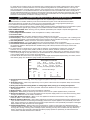
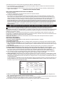
The table shows the correct size to use depending on cord length and nameplate ampere rating. If in doubt, use the
next heavier gauge. The smaller the gauge number, the heavier the cord.
10) Avoid Unintentional Starting – Donʼt carry plugged-in appliance with finger on switch. Be sure switch is off when
plugging in.
11) Donʼt Abuse Cord – Never carry appliance by cord or yank it to disconnect from receptacle. Keep cord from heat,
oil, and sharp edges.
12) Donʼt grasp the exposed cutting blades or cutting edges when picking up or holding the appliance.
13) Donʼt Force Appliance – It will do the job better and with less likelihood of a risk of injury at the rate for which it
was designed.
14) Donʼt Overreach – Keep proper footing and balance at all times.
15) Stay Alert – Watch what you are doing. Use common sense. Do not operate appliance when you are tired.
16) Disconnect Appliance – Disconnect the appliance from the power supply when not in use, before servicing, when
changing accessories such as blades, and the like.
17) Store Idle Appliances Indoors – When not in use, appliances should be stored indoors in dry, and high or
locked-up place – out of reach of children.
18) Maintain Appliance With Care – Keep cutting edge sharp and clean for best performance and to reduce the risk of
injury. Follow instructions for lubricating and changing accessories. Inspect appliance cord periodically, and if dam
aged, have it repaired by an authorized service facility. Inspect extension cords periodically and replace if damaged.
Keep handles dry, clean and free from oil and grease.
19) Check Damaged Parts – Before further use of the appliance, a guard or other part that is damaged should be
carefully checked to determine that it will operate properly and perform its intended function. Check for alignment of
moving parts, binding of moving parts, breakage of parts, mounting, and any other condition that may affect its op
eration. A guard or other part that is damaged should be properly repaired or replaced by an authorized service
center unless indicated elsewhere in this manual.
Minimum Gauge for Cord Sets
Volts Total Length of Cord in Feet
120V 0-25 26-50 51-100 101-150
(0-7,6m) (7,6-15,2m) (15,2-30,4m) (30,4-45,7m)
240V 0-50 51-100 101-200 201-300
(0-15,2m) (15,2-30,4m) (30,4-60,9m) (60,9-91,4m)
Ampere Rating
More Not more American Wire Gauge
Than Than
0 - 6 18 16 16 14
6 - 10 18 16 14 12
10 - 12 16 16 14 12
12 - 16 14 12 Not Recommended
4

WARNING: Some dust created by this product contains chemicals known to the State of California to cause
cancer, birth defects or other reproductive harm.
Some examples of these chemicals are:
• compounds in fertilizers
• compounds in insecticides, herbicides and pesticides
• arsenic and chromium from chemically treated lumber
To reduce your exposure to these chemicals, wear approved safety equipment such as dust masks that are specially
designed to filter out microscopic particles.
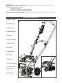
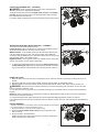
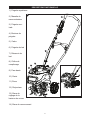
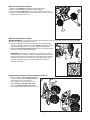
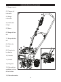
FUNCTIONAL DESCRIPTION
1.) Upper handle
2.) Switch lever
3.) Mid handle
4.) Handle knobs
5.) Frame
6.) Ballast handle
7.) Ballast tank
8.) Fill port
9.) Tine shield
10.) Tines
11.) Wheel
12.) Circuit breaker
13.) Wheel height
assembly bar
14.) Drag bar
1
11
9
7
6
2
10
8
A
3
4
5
12
14
13
5

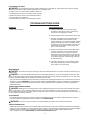
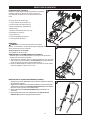
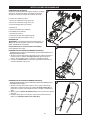
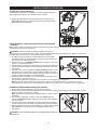
ASSEMBLY INSTRUCTIONS
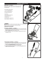
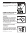
UNPACKING - (FIGURE B)
Remove the frame / upper handle assembly, mid handle,
ballast tank, wheels, drag bar, tines and hardware bag
from the carton.
The hardware bag contains:
1. Long Carriage Bolts (2)
2. Short Carriage Bolts (4)
3. Flanged Hex Nuts (4)
4. Knobs (2)
5. Wheel Machine Bolts (2)
6. Wheel Washers (4)
7. Steel Pin (1)
8. Long Hairpin Cotter Pin (2)
9. Short Hairpin Cotter Pin (1)
ASSEMBLY
DANGER: To prevent serious personal injury, do not connect electric
extension cord to unit until fully completing assembly.
Tools required for assembly:
Adjustable or 10 mm wrench
MID HANDLE ASSEMBLY - (FIGURE C)
Ensure that the cord is not pinched and is routed on the top side of the handles.
1. Align the holes in the mid handle with holes in the frame and insert the
short carriage bolts (C-1) through the holes.
2. Place a nut (C-2) on each bolt and tighten securely with a 10 mm or
adjustable wrench.
UPPER HANDLE ASSEMBLY - (FIGURE D)
Ensure that the cord is not pinched and is routed on the top side of the handles.
1. Align the holes in the upper handle with holes in the mid handle and
insert the long carriage bolts (D-1) through the holes.
2. Hand tighten plastic knob (D-2) onto carriage bolts.
3. Clip the lower part of the cord into the lower cord clip (D-3) after the
handles are fastened together.
B
C
3
D
6

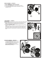
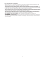
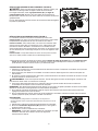
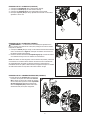
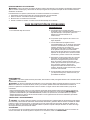
WHEEL ASSEMBLY - (FIGURE E)
1. Place a washer (E-1) on each end of the axle.
2. Place a wheel (E-3) on each end of the axle.
3. Place another washer (E-1) on the outside of the wheel.
3. Thread bolt (E-2) into axle. Tighten securely with a 10 mm or
adjustable wrench.
TINE ASSEMBLY - (FIGURE F)
WARNING: Garden tiller tines are sharp. Always wear leather gloves to protect your hands when handling tines.
1. Place a tine (F-1) with the fins facing inward on the axle as shown in
figure F. Place another tine against it with the fins facing out.
2. Insert the long hairpin cotter pin (F-2) through the hole in the end of
the axle as shown in the inset.
NOTE: For tilling in a narrow area, such as between plant rows, it may
be desirable to leave the outer tine pairs off. Unplug the tiller before
removing the outer tine. Ensure that the cotter pin is inserted in the
inner hole location on the axle when only the inner tine positions are
used.
DRAG BAR ASSEMBLY - (FIGURE G)
1. Insert the drag bar (G-1) through the slot in
the drag bar bracket (G-2). Align the hole in
the drag bar with the hole in the bracket and
insert the locating pin (G-3). Push the
hairpin cotter pin (G-4) through the hole in
the end of the bolt to secure.
E
F
G
7

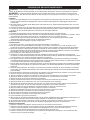
OPERATING INSTRUCTIONS
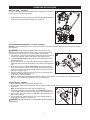
BALLAST TANK - (FIGURE H)
To improve the tilling performance, ballast (extra weight), can be added to
the tiller with the provided ballast tank.
1. Fill the ballast tank with dry sand only. Open the door (H-1) of the tank
and pour in the fill material to the MAX line on the tank.
ATTACHING EXTENSION CORD TO TILLER - (FIGURE I)
DO NOT connect the extension cord to power source until you have finished reading this manual and you are ready to
start operation.
DANGER: Avoid accidental starting. Make sure you are in the
operating position behind the tiller when using it. To avoid serious injury,
the operator and unit should be in a stable position while starting.
1. The extension cord must be polarized and will only plug in one way, by
orienting the wide slot with the wide blade in the switch housing.
2. Loop the extension cord (I-1) and push the loop up through the hole in
the switch housing.
3. Pull the extension cord on the side of the loop that is plugged into the
switch housing and remove all the slack in this section of the extension
cord.
4. Place the loop over the strain relief tab (I-2) on the switch housing
and pull the extension cord so the loop draws down around the strain
relief tab as shown in the detail. Double check to see that you did not
loosen the extension cord.
5. Plug the extension cord into a 120 volt, 60 cycle AC grounded outlet.
The tiller will operate satisfactorily on a
circuit with a 15 ampere breaker.
Note: To avoid tripping circuit breakers, select an outlet on a circuit that is not overloaded. Do not select an outlet
that is on a circuit with other appliances such as a refrigerator.
ON-OFF SWITCH - FIGURE J
1. Stand behind the tiller and grasp the upper handle.
2. Pivot the tiller slightly toward the rear, so that its weight is resting on its wheels and the tines are not in contact with
the ground.
Note: Starting the tiller motor also starts the tilling action.
3. To operate the switch, insert your finger into the opening (J-1) and
push the lever (J-2) out so that you can grasp it with your other hand.
4. Pull the lever back to turn the unit on and hold it against the tiller han-
dle to keep it running.
5. To turn the tiller off, release the lever. The spring loaded "SNAP AC-
TION" lever will quickly turn the tiller off.
DANGER: NEVER ATTEMPT TO OVERRIDE THE OPERATION OF
THIS SWITCH.
H
I
J
8
H1

ADJUSTING THE DRAG BAR - (FIGURE K)
DANGER: Avoid accidental starting. Stop motor and disconnect
extension cord prior to adjusting the drag bar.
To adjust the drag bar, remove the hairpin cotter pin (K-1) and locating
pin (K-2). Align the drag bar hole in the desired position with the frame
hole. Reinsert bolt and cotter pin.
For deeper tilling, the drag bar should be positioned in the lowest position.
ADJUSTING THE WHEEL HEIGHT POSITION - (FIGURE L)
The Tiller has three wheel height positions.
Lowest Position - When the wheels are in their lowest position this will
allow easy transportation to and from your work area.
Middle Position - In the middle position the wheels will be lifted up, but
can still contact the ground. This may provide some users additional
control and stability while tilling. It is recommended to raise or remove the
drag bar when tilling in this wheel position.
Highest Position - In the highest position the wheels will not contact the
ground. This position can be used for deep tilling.
1. To adjust the wheel height position remove the hairpin cotter pin (L-
1) and locating pin (L-2). Align the desired wheel assembly connect-
ing rod hole with the frame bracket hole. Replace bolt and cotter pin.
USING THE TILLER
1. Move the tiller to the work area prior to starting the motor. Transport the tiller by pushing or pulling it along on its
wheels.
2. Attach the extension cord and start the tiller following all steps under On-Off Switch section.
3. With both hands on the upper handle, slowly pivot the tiller forward until the tines make contact with the soil.
WARNING: Avoid risk of injury. Keep the extension cord clear of the tilling path at all times. Do not allow the
tines to contact the extension cord.
4. Once the tines are in the ground, till at a moderate pace until you are familiar with the controls and the handling of
the tiller.
NOTE: Be aware of the extension cord's location at all times. Never allow the tiller's tines to come into contact with
the extension cord while operating.
5. To adjust the tilling depth, adjust the drag bar bracket and wheel height adjustment position as required.
6. For deeper tilling move your tiller slowly back and forth. Work the same area over and over until the desired depth is
reached.
CIRCUIT BREAKER
The tiller is protected from overheating with a manually resettable circuit breaker. It
may require resetting if an overload condition existed.
1. Unplug the extension cord from the tiller switch housing.
2. Press the circuit breaker button (M-1) at the rear left side of the
motor housing.
3. Plug cord back in and restart tiller.
NOTE: The tiller may need a few minutes to cool down. Pushing the
breaker button back in will reset it.
9
K
L
M

UNJAMMING THE TINES
DANGER: Avoid accidental starting. Release switch lever to turn tiller off, wait until the tines stop and unplug
extension cord from the tiller switch housing prior to unjamming tines.
To unjam a rock or to clear debris tangled in the tines:
1. Unplug extension cord from the tiller switch housing.
2. Remove the tines. Refer to Tine Assembly section.
3. Clear all debris from the tines.
4. Reinstall the tines. Refer to Tine Assembly section.
TROUBLESHOOTING GUIDE
PROBLEM RECOMMENDATION
1. Tiller stops operating. A. Check that the extension cord plug is fully
inserted into the switch housing. Check that
other end is still plugged into outlet.
B. Check that the house circuit breaker did not trip.
C. The tiller is protected from overheating with a
manually resettable circuit breaker. It may
require resetting if an overload condition existed.
Unplug the extension cord from the tiller switch
housing. Press the circuit breaker button at the
rear left side of the motor housing. Plug cord
back in and restart tiller.
D. Unplug the extension cord from the tiller switch
housing. Inspect the tines to make sure your
tines are clear of rocks or debris. Clear any
debris that may prevent the tines from spinning.
If necessary, remove the tines to make sure all
of the debris has been cleared. Plug cord back
in and restart tiller.
E. If the tiller continues to stop operating and the
tiller circuit breaker trips, slow the tilling pace
down and do not dig as deep.
MAINTENANCE
DANGER: To prevent serious personal injury, disconnect electric extension cord from unit before performing any
maintenance.
DANGER: Do not wash garden tiller with a hose. Avoid getting water on motor and electrical connections. After
tilling, the mud and debris may be easily removed from the tines by removing them from the tiller first. You may spray
the tines with water while they are detached and away from the tiller.
Use only mild soap and damp cloth to clean the tool. Never let any liquid get inside the tool; never immerse any part of
the tool into a liquid. IMPORTANT: To assure product SAFETY and RELIABILITY, repairs, maintenance and adjustment
should be performed by authorized service centers or other qualified service organizations, always using identical
replacement parts.
TRANSPORTING AND STORAGE
DANGER: Rotating tines can cause serious injury. Release switch lever to turn tiller off and unplug cord before
lifting, transporting or storing the tiller. Never pick up or carry the unit while the motor is running, serious personal
injury could result. Store in a dry place. Note: The tiller will not be as heavy to lift if the ballast tank is removed first. Do
not use ballast tank handle to lift unit.
ACCESSORIES
Recommended accessories for use with your tiller are available from your local dealer or authorized service center. If
you need assistance regarding accessories, please call: 1-800-544-6986
WARNING: The use of any accessory not recommended for use with this tool could be hazardous.
SERVICE INFORMATION
All Black & Decker Service Centers are staffed with trained personnel to provide customers with efficient and reliable
power tool service. Whether you need technical advice, repair, or genuine factory replacement parts, contact the Black
& Decker location nearest you. To find your local service location, refer to the yellow page directory under
"Tools—Electric" or call: 1-800-544-6986 or visit www.blackanddecker.com
10

FULL TWO-YEAR HOME USE WARRANTY
Black & Decker (U.S.) Inc. warrants this product for two years against any defects in material or workmanship. The
defective product will be replaced or repaired at no charge in either of two ways.
The first, which will result in exchanges only, is to return the product to the retailer from whom it was purchased
(provided that the store is a participating retailer). Returns should be made within the time period of the retailerʼs policy
for exchanges (usually 30 to 90 days after the sale). Proof of purchase may be required. Please check with the retailer
for their specific return policy regarding returns that are beyond the time set for exchanges.
The second option is to take or send the product (prepaid) to a Black & Decker owned or authorized Service Center for
repair or replacement at our option. Proof of purchase may be required.Black & Decker owned and authorized Service
Centers are listed under "Tools-Electric" in the yellow pages of the phone directory.
This warranty does not apply to accessories. This warranty gives you specific legal rights and you may have other
rights which vary from state to state or province to province. Should you have any questions, contact the manager of
your nearest Black & Decker Service Center. This product is not intended for commercial use.
FREE WARNING LABEL REPLACEMENT: If your warning labels become illegible or are missing, call
1-800-544-6986 for a free replacement.
LATIN AMERICA: This warranty does not apply to products sold in Latin America. For products sold in Latin America,
check country specific warranty information contained in the packaging, call the local company or see the website for
warranty information.
11
Page is loading ...
Page is loading ...
Page is loading ...
Page is loading ...
Page is loading ...
Page is loading ...
Page is loading ...
Page is loading ...
Page is loading ...
Page is loading ...
Page is loading ...
Page is loading ...
Page is loading ...
Page is loading ...
Page is loading ...
Page is loading ...
Page is loading ...
Page is loading ...
Page is loading ...
Page is loading ...
Page is loading ...
Page is loading ...
Page is loading ...
Page is loading ...
Page is loading ...
-
 1
1
-
 2
2
-
 3
3
-
 4
4
-
 5
5
-
 6
6
-
 7
7
-
 8
8
-
 9
9
-
 10
10
-
 11
11
-
 12
12
-
 13
13
-
 14
14
-
 15
15
-
 16
16
-
 17
17
-
 18
18
-
 19
19
-
 20
20
-
 21
21
-
 22
22
-
 23
23
-
 24
24
-
 25
25
-
 26
26
-
 27
27
-
 28
28
-
 29
29
-
 30
30
-
 31
31
-
 32
32
-
 33
33
-
 34
34
-
 35
35
-
 36
36


Black & Decker TL10 User manual
- Category
- Mini tillers
- Type
- User manual
Ask a question and I''ll find the answer in the document
Finding information in a document is now easier with AI
in other languages
- français: Black & Decker TL10 Manuel utilisateur
- español: Black & Decker TL10 Manual de usuario
Related papers
-
Black & Decker CTL36 User manual
-
-
Black & Decker HT22 User manual
-
-
BLACK DECKER HG1300 User manual
-
-
-
-
-
Other documents
-
Craftsman 917.293340 Owner's manual
-
 Poulan Pro DRT70 User manual
-
Poulan 401423 User manual
-
-
-
-
Husqvarna DRT900H Owner's manual
-
Troy-Bilt 12212 User manual
-
-
 EarthQuake 29409 User manual

