Page is loading ...

8 ft, 12 ft, and 16 ft
OM-252 045B 2011−10
Processes
Description
MIG (GMAW) Welding
Flux Cored (FCAW) Welding
(Gas-and Self-Shielding)
Submerged (SAW) Welding
Boom w/drive
S-74 Boom w/Drive
Visit our website at
www.MillerWelds.com
File: MIG (GMAW)

Miller Electric manufactures a full line
of welders and welding related equipment.
For information on other quality Miller
products, contact your local Miller distributor to receive the latest full
line catalog or individual specification sheets. To locate your nearest
distributor or service agency call 1-800-4-A-Miller, or visit us at
www.MillerWelds.com on the web.
Thank you and congratulations on choosing Miller. Now you can get
the job done and get it done right. We know you don’t have time to do
it any other way.
That’s why when Niels Miller first started building arc welders in 1929,
he made sure his products offered long-lasting value and superior
quality. Like you, his customers couldn’t afford anything less. Miller
products had to be more than the best they could be. They had to be the
best you could buy.
Today, the people that build and sell Miller products continue the
tradition. They’re just as committed to providing equipment and service
that meets the high standards of quality and value established in 1929.
This Owner’s Manual is designed to help you get the most out of your
Miller products. Please take time to read the Safety precautions. They
will help you protect yourself against potential hazards on the worksite.
We’ve made installation and operation quick
and easy. With Miller you can count on years
of reliable service with proper maintenance.
And if for some reason the unit needs repair,
there’s a Troubleshooting section that will
help you figure out what the problem is. The
parts list will then help you to decide the
exact part you may need to fix the problem.
Warranty and service information for your
particular model are also provided.
Miller is the first welding
equipment manufacturer in
the U.S.A. to be registered to
the ISO 9001:2000 Quality
System Standard.
Working as hard as you do
− every power source from
Miller is backed by the most
hassle-free warranty in the
business.
From Miller to You
Mil_Thank 2009−09

TABLE OF CONTENTS
SECTION 1 − SAFETY PRECAUTIONS - READ BEFORE USING 1...................................
1-1. Symbol Usage 1........................................................................
1-2. Arc Welding Hazards 1..................................................................
1-3. Additional Symbols For Installation, Operation, And Maintenance 3.............................
1-4. California Proposition 65 Warnings 4.......................................................
1-5. Principal Safety Standards 4.............................................................
1-6. EMF Information 4......................................................................
SECTION 2 − CONSIGNES DE SÉCURITÉ − LIRE AVANT UTILISATION 5............................
2-1. Symboles utilisés 5.....................................................................
2-2. Dangers relatifs au soudage à l’arc 5......................................................
2-3. Dangers supplémentaires en relation avec l’installation, le fonctionnement et la maintenance 7......
2-4. Proposition californienne 65 Avertissements 8...............................................
2-5. Principales normes de sécurité 9..........................................................
2-6. Informations relatives aux CEM 9.........................................................
SECTION 3 − INTRODUCTION 11.................................................................
3-1. Specifications 11........................................................................
SECTION 4 − INSTALLATION 11..................................................................
4-1. Serial Number And Stock Number Label Location 11..........................................
4-2. Installing Swivel Into Pipe Post 11..........................................................
4-3. Adjusting Control Tilt Bracket 12...........................................................
4-4. Installing Boom And Reel Support 12.......................................................
4-5. Installing Wire Guide Extension 13.........................................................
4-6. Equipment Connection Diagram 13.........................................................
4-7. Control Box Connections 14...............................................................
4-8. 14-Pin Plug Information 14................................................................
4-9. Removing Safety Collar And Adjusting Boom 15..............................................
4-10. Wire Type, Size, And Feed Speed Capability Table 15.........................................
4-11. Installing And Threading Welding Wire 16....................................................
SECTION 5 − MAINTENANCE 17.................................................................
5-1. Routine Maintenance 17..................................................................
5-2. Troubleshooting 17......................................................................
SECTION 6 − PARTS LIST 18.....................................................................
WARRANTY
OM-252 045 Page 1
SECTION 1 − SAFETY PRECAUTIONS - READ BEFORE USING
som 2011−01
7
Protect yourself and others from injury — read and follow these precautions.
1-1. Symbol Usage
DANGER! − Indicates a hazardous situation which, if
not avoided, will result in death or serious injury. The
possible hazards are shown in the adjoining symbols
or explained in the text.
Indicates a hazardous situation which, if not avoided,
could result in death or serious injury. The possible
hazards are shown in the adjoining symbols or ex-
plained in the text.
NOTICE − Indicates statements not related to personal injury.
. Indicates special instructions.
This group of symbols means Warning! Watch Out! ELECTRIC
SHOCK, MOVING PARTS, and HOT PARTS hazards. Consult sym-
bols and related instructions below for necessary actions to avoid the
hazards.
1-2. Arc Welding Hazards
The symbols shown below are used throughout this manual
to call attention to and identify possible hazards. When you
see the symbol, watch out, and follow the related instructions
to avoid the hazard. The safety information given below is
only a summary of the more complete safety information
found in the Safety Standards listed in Section 1-5. Read and
follow all Safety Standards.
Only qualified persons should install, operate, maintain, and
repair this unit.
During operation, keep everybody, especially children, away.
ELECTRIC SHOCK can kill.
Touching live electrical parts can cause fatal shock
s
or severe burns. The electrode and work circuit i
s
electrically live whenever the output is on. The inpu
t
power circuit and machine internal circuits are also
live when power is on. In semiautomatic or automati
c
wire welding, the wire, wire reel, drive roll housing
,
and all metal parts touching the welding wire are
electrically live. Incorrectly installed or improperl
y
grounded equipment is a hazard.
D Do not touch live electrical parts.
D Wear dry, hole-free insulating gloves and body protection.
D Insulate yourself from work and ground using dry insulating mats
or covers big enough to prevent any physical contact with the work
or ground.
D Do not use AC output in damp areas, if movement is confined, or if
there is a danger of falling.
D Use AC output ONLY if required for the welding process.
D If AC output is required, use remote output control if present on
unit.
D Additional safety precautions are required when any of the follow-
ing electrically hazardous conditions are present: in damp
locations or while wearing wet clothing; on metal structures such
as floors, gratings, or scaffolds; when in cramped positions such
as sitting, kneeling, or lying; or when there is a high risk of unavoid-
able or accidental contact with the workpiece or ground. For these
conditions, use the following equipment in order presented: 1) a
semiautomatic DC constant voltage (wire) welder, 2) a DC manual
(stick) welder, or 3) an AC welder with reduced open-circuit volt-
age. In most situations, use of a DC, constant voltage wire welder
is recommended. And, do not work alone!
D Disconnect input power or stop engine before installing or
servicing this equipment. Lockout/tagout input power according to
OSHA 29 CFR 1910.147 (see Safety Standards).
D Properly install and ground this equipment according to its
Owner’s Manual and national, state, and local codes.
D Always verify the supply ground − check and be sure that input
power cord ground wire is properly connected to ground terminal in
disconnect box or that cord plug is connected to a properly
grounded receptacle outlet.
D When making input connections, attach proper grounding conduc-
tor first − double-check connections.
D Keep cords dry, free of oil and grease, and protected from hot metal
and sparks.
D Frequently inspect input power cord for damage or bare wiring −
replace cord immediately if damaged − bare wiring can kill.
D Turn off all equipment when not in use.
D Do not use worn, damaged, undersized, or poorly spliced cables.
D Do not drape cables over your body.
D If earth grounding of the workpiece is required, ground it directly
with a separate cable.
D Do not touch electrode if you are in contact with the work, ground,
or another electrode from a different machine.
D Do not touch electrode holders connected to two welding ma-
chines at the same time since double open-circuit voltage will be
present.
D Use only well-maintained equipment. Repair or replace damaged
parts at once. Maintain unit according to manual.
D Wear a safety harness if working above floor level.
D Keep all panels and covers securely in place.
D Clamp work cable with good metal-to-metal contact to workpiece
or worktable as near the weld as practical.
D Insulate work clamp when not connected to workpiece to prevent
contact with any metal object.
D Do not connect more than one electrode or work cable to any
single weld output terminal.
SIGNIFICANT DC VOLTAGE exists in inverter weld-
ing power sources AFTER removal of input power.
D Turn Off inverter, disconnect input power, and discharge input
capacitors according to instructions in Maintenance Section
before touching any parts.
HOT PARTS can burn.
D Do not touch hot parts bare handed.
D Allow cooling period before working on equip-
ment.
D To handle hot parts, use proper tools and/or
wear heavy, insulated welding gloves and
clothing to prevent burns.
OM-252 045 Page 2
Welding produces fumes and gases. Breathing
these fumes and gases can be hazardous to your
health.
FUMES AND GASES can be hazardous.
D Keep your head out of the fumes. Do not breathe the fumes.
D If inside, ventilate the area and/or use local forced ventilation at the
arc to remove welding fumes and gases.
D If ventilation is poor, wear an approved air-supplied respirator.
D Read and understand the Material Safety Data Sheets (MSDSs)
and the manufacturer’s instructions for metals, consumables,
coatings, cleaners, and degreasers.
D Work in a confined space only if it is well ventilated, or while
wearing an air-supplied respirator. Always have a trained watch-
person nearby. Welding fumes and gases can displace air and
lower the oxygen level causing injury or death. Be sure the breath-
ing air is safe.
D Do not weld in locations near degreasing, cleaning, or spraying op-
erations. The heat and rays of the arc can react with vapors to form
highly toxic and irritating gases.
D Do not weld on coated metals, such as galvanized, lead, or
cadmium plated steel, unless the coating is removed from the weld
area, the area is well ventilated, and while wearing an air-supplied
respirator. The coatings and any metals containing these elements
can give off toxic fumes if welded.
Arc rays from the welding process produce intense
visible and invisible (ultraviolet and infrared) rays
that can burn eyes and skin. Sparks fly off from the
weld.
D Wear an approved welding helmet fitted with a proper shade of
filter lenses to protect your face and eyes from arc rays and
sparks when welding or watching (see ANSI Z49.1 and Z87.1
listed in Safety Standards).
D Wear approved safety glasses with side shields under your
helmet.
D Use protective screens or barriers to protect others from flash,
glare and sparks; warn others not to watch the arc.
D Wear protective clothing made from durable, flame-resistant
material (leather, heavy cotton, or wool) and foot protection.
ARC RAYS can burn eyes and skin.
Welding on closed containers, such as tanks,
drums, or pipes, can cause them to blow up. Sparks
can fly off from the welding arc. The flying sparks, hot
workpiece, and hot equipment can cause fires and
burns. Accidental contact of electrode to metal objects can cause
sparks, explosion, overheating, or fire. Check and be sure the area is
safe before doing any welding.
WELDING can cause fire or explosion.
D Remove all flammables within 35 ft (10.7 m) of the welding arc. If
this is not possible, tightly cover them with approved covers.
D Do not weld where flying sparks can strike flammable material.
D Protect yourself and others from flying sparks and hot metal.
D Be alert that welding sparks and hot materials from welding can
easily go through small cracks and openings to adjacent areas.
D Watch for fire, and keep a fire extinguisher nearby.
D Be aware that welding on a ceiling, floor, bulkhead, or partition can
cause fire on the hidden side.
D Do not weld on closed containers such as tanks, drums, or pipes,
unless they are properly prepared according to AWS F4.1 (see
Safety Standards).
D Do not weld where the atmosphere may contain flammable dust,
gas, or liquid vapors (such as gasoline).
D Connect work cable to the work as close to the welding area as
practical to prevent welding current from traveling long, possibly
unknown paths and causing electric shock, sparks, and fire
hazards.
D Do not use welder to thaw frozen pipes.
D Remove stick electrode from holder or cut off welding wire at
contact tip when not in use.
D Wear oil-free protective garments such as leather gloves, heavy
shirt, cuffless trousers, high shoes, and a cap.
D Remove any combustibles, such as a butane lighter or matches,
from your person before doing any welding.
D After completion of work, inspect area to ensure it is free of sparks,
glowing embers, and flames.
D Use only correct fuses or circuit breakers. Do not oversize or by-
pass them.
D Follow requirements in OSHA 1910.252 (a) (2) (iv) and NFPA 51B
for hot work and have a fire watcher and extinguisher nearby.
FLYING METAL or DIRT can injure eyes.
D Welding, chipping, wire brushing, and grinding
cause sparks and flying metal. As welds cool,
they can throw off slag.
D Wear approved safety glasses with side
shields even under your welding helmet.
BUILDUP OF GAS can injure or kill.
D Shut off compressed gas supply when not in use.
D Always ventilate confined spaces or use
approved air-supplied respirator.
ELECTRIC AND MAGNETIC FIELDS (EM
F)
can affect Implanted Medical Devices.
D Wearers of Pacemakers and other Implante
d
Medical Devices should keep away.
D Implanted Medical Device wearers should consult their docto
r
and the device manufacturer before going near arc welding, spo
t
welding, gouging, plasma arc cutting, or induction heating
operations.
NOISE can damage hearing.
Noise from some processes or equipment can
damage hearing.
D Wear approved ear protection if noise level is
high.
Compressed gas cylinders contain gas under high
pressure. If damaged, a cylinder can explode. Since
gas cylinders are normally part of the welding
process, be sure to treat them carefully.
CYLINDERS can explode if damaged.
D Protect compressed gas cylinders from excessive heat, mechani-
cal shocks, physical damage, slag, open flames, sparks, and arcs.
D Install cylinders in an upright position by securing to a stationary
support or cylinder rack to prevent falling or tipping.
D Keep cylinders away from any welding or other electrical circuits.
D Never drape a welding torch over a gas cylinder.
D Never allow a welding electrode to touch any cylinder.
D Never weld on a pressurized cylinder − explosion will result.
D Use only correct compressed gas cylinders, regulators, hoses,
and fittings designed for the specific application; maintain them
and associated parts in good condition.
D Turn face away from valve outlet when opening cylinder valve.
D Keep protective cap in place over valve except when cylinder is in
use or connected for use.
D Use the right equipment, correct procedures, and sufficient num-
ber of persons to lift and move cylinders.
D Read and follow instructions on compressed gas cylinders,
associated equipment, and Compressed Gas Association (CGA)
publication P-1 listed in Safety Standards.
OM-252 045 Page 3
1-3. Additional Symbols For Installation, Operation, And Maintenance
FIRE OR EXPLOSION hazard.
D Do not install or place unit on, over, or near
combustible surfaces.
D Do not install unit near flammables.
D Do not overload building wiring − be sure power supply system is
properly sized, rated, and protected to handle this unit.
FALLING EQUIPMENT can injure.
D Use lifting eye to lift unit only, NOT running
gear, gas cylinders, or any other accessories.
D Use equipment of adequate capacity to lift and
support unit.
D If using lift forks to move unit, be sure forks are long enough to
extend beyond opposite side of unit.
D Keep equipment (cables and cords) away from moving vehicles
when working from an aerial location.
D Follow the guidelines in the Applications Manual for the Revised
NIOSH Lifting Equation (Publication No. 94−110) when manu-
ally lifting heavy parts or equipment.
OVERUSE can cause OVERHEATING
D Allow cooling period; follow rated duty cycle.
D Reduce current or reduce duty cycle before
starting to weld again.
D Do not block or filter airflow to unit.
FLYING SPARKS can injure.
D Wear a face shield to protect eyes and face.
D Shape tungsten electrode only on grinder with
proper guards in a safe location wearing proper
face, hand, and body protection.
D Sparks can cause fires — keep flammables away.
STATIC (ESD) can damage PC boards.
D Put on grounded wrist strap BEFORE handling
boards or parts.
D Use proper static-proof bags and boxes to
store, move, or ship PC boards.
MOVING PARTS can injure.
D Keep away from moving parts.
D Keep away from pinch points such as drive
rolls.
WELDING WIRE can injure.
D Do not press gun trigger until instructed to do
so.
D Do not point gun toward any part of the body,
other people, or any metal when threading
welding wire.
MOVING PARTS can injure.
D Keep away from moving parts such as fans.
D Keep all doors, panels, covers, and guards
closed and securely in place.
D Have only qualified persons remove doors, panels, covers, or
guards for maintenance and troubleshooting as necessary.
D Reinstall doors, panels, covers, or guards when maintenance is
finished and before reconnecting input power.
READ INSTRUCTIONS.
D Read and follow all labels and the Owner’s
Manual carefully before installing, operating, or
servicing unit. Read the safety information at
the beginning of the manual and in each
section.
D Use only genuine replacement parts from the manufacturer.
D Perform maintenance and service according to the Owner’s
Manuals, industry standards, and national, state, and local
codes.
H.F. RADIATION can cause interference.
D High-frequency (H.F.) can interfere with radio
navigation, safety services, computers, and
communications equipment.
D Have only qualified persons familiar with
electronic equipment perform this installation.
D The user is responsible for having a qualified electrician prompt-
ly correct any interference problem resulting from the installa-
tion.
D If notified by the FCC about interference, stop using the
equipment at once.
D Have the installation regularly checked and maintained.
D Keep high-frequency source doors and panels tightly shut, keep
spark gaps at correct setting, and use grounding and shielding to
minimize the possibility of interference.
ARC WELDING can cause interference.
D Electromagnetic energy can interfere with
sensitive electronic equipment such as
computers and computer-driven equipment
such as robots.
D Be sure all equipment in the welding area is
electromagnetically compatible.
D To reduce possible interference, keep weld cables as short as
possible, close together, and down low, such as on the floor.
D Locate welding operation 100 meters from any sensitive elec-
tronic equipment.
D Be sure this welding machine is installed and grounded
according to this manual.
D If interference still occurs, the user must take extra measures
such as moving the welding machine, using shielded cables,
using line filters, or shielding the work area.

OM-252 045 Page 4
1-4. California Proposition 65 Warnings
Welding or cutting equipment produces fumes or gases
which contain chemicals known to the State of California to
cause birth defects and, in some cases, cancer. (California
Health & Safety Code Section 25249.5 et seq.)
Battery posts, terminals and related accessories contain lead
and lead compounds, chemicals known to the State of
California to cause cancer and birth defects or other
reproductive harm. Wash hands after handling.
This product contains chemicals, including lead, known to
the state of California to cause cancer, birth defects, or other
reproductive harm. Wash hands after use.
For Gasoline Engines:
Engine exhaust contains chemicals known to the State of
California to cause cancer, birth defects, or other reproduc-
tive harm.
For Diesel Engines:
Diesel engine exhaust and some of its constituents are
known to the State of California to cause cancer, birth
defects, and other reproductive harm.
1-5. Principal Safety Standards
Safety in Welding, Cutting, and Allied Processes, ANSI Standard Z49.1,
from Global Engineering Documents (phone: 1-877-413-5184, website:
www.global.ihs.com).
Safe Practices for the Preparation of Containers and Piping for Welding
and Cutting, American Welding Society Standard AWS F4.1, from Glob-
al Engineering Documents (phone: 1-877-413-5184, website:
www.global.ihs.com).
National Electrical Code, NFPA Standard 70, from National Fire Protec-
tion Association, Quincy, MA 02269 (phone: 1-800-344-3555, website:
www.nfpa.org and www. sparky.org).
Safe Handling of Compressed Gases in Cylinders, CGA Pamphlet P-1,
from Compressed Gas Association, 4221 Walney Road, 5th Floor,
Chantilly, VA 20151 (phone: 703-788-2700, website:www.cganet.com).
Safety in Welding, Cutting, and Allied Processes, CSA Standard
W117.2, from Canadian Standards Association, Standards Sales, 5060
Spectrum Way, Suite 100, Ontario, Canada L4W 5NS (phone:
800-463-6727, website: www.csa-international.org).
Safe Practice For Occupational And Educational Eye And Face Protec-
tion, ANSI Standard Z87.1, from American National Standards Institute,
25 West 43rd Street, New York, NY 10036 (phone: 212-642-4900, web-
site: www.ansi.org).
Standard for Fire Prevention During Welding, Cutting, and Other Hot
Work, NFPA Standard 51B, from National Fire Protection Association,
Quincy, MA 02269 (phone: 1-800-344-3555, website: www.nfpa.org.
OSHA, Occupational Safety and Health Standards for General Indus-
try, Title 29, Code of Federal Regulations (CFR), Part 1910, Subpart Q,
and Part 1926, Subpart J, from U.S. Government Printing Office, Super-
intendent of Documents, P.O. Box 371954, Pittsburgh, PA 15250-7954
(phone: 1-866-512-1800) (there are 10 OSHA Regional Offices—
phone for Region 5, Chicago, is 312-353-2220, website:
www.osha.gov).
U.S. Consumer Product Safety Commission (CPSC), 4330 East West
Highway, Bethesda, MD 20814 (phone: 301-504-7923, website:
www.cpsc.gov).
Applications Manual for the Revised NIOSH Lifting Equation, The Na-
tional Institute for Occupational Safety and Health (NIOSH), 1600
Clifton Rd, Atlanta, GA 30333 (phone: 1-800-232-4636, website:
www.cdc.gov/NIOSH).
1-6. EMF Information
Electric current flowing through any conductor causes localized electric
and magnetic fields (EMF). Welding current creates an EMF field
around the welding circuit and welding equipment. EMF fields may inter-
fere with some medical implants, e.g. pacemakers. Protective
measures for persons wearing medical implants have to be taken. For
example, access restrictions for passers−by or individual risk assess-
ment for welders. All welders should use the following procedures in
order to minimize exposure to EMF fields from the welding circuit:
1. Keep cables close together by twisting or taping them, or using a
cable cover.
2. Do not place your body between welding cables. Arrange cables
to one side and away from the operator.
3. Do not coil or drape cables around your body.
4. Keep head and trunk as far away from the equipment in the
welding circuit as possible.
5. Connect work clamp to workpiece as close to the weld as
possible.
6. Do not work next to, sit or lean on the welding power source.
7. Do not weld whilst carrying the welding power source or wire
feeder.
About Implanted Medical Devices:
Implanted Medical Device wearers should consult their doctor and the
device manufacturer before performing or going near arc welding, spot
welding, gouging, plasma arc cutting, or induction heating operations.
If cleared by your doctor, then following the above procedures is recom-
mended.

OM-252 045 Page 9
2-5. Principales normes de sécurité
Safety in Welding, Cutting, and Allied Processes, ANSI Standard Z49.1,
de Global Engineering Documents (téléphone : 1-877-413-5184, site
Internet : www.global.ihs.com).
Safe Practices for the Preparation of Containers and Piping for Welding
and Cutting, American Welding Society Standard AWS F4.1, de Global
Engineering Documents (téléphone : 1-877-413-5184, site internet :
www.global.ihs.com).
National Electrical Code, NFPA Standard 70, de National Fire Protec-
tion Association, Quincy, MA 02269 (téléphone : 800-344-3555, site
Internet : www.nfpa.org et www.sparky.org).
Safe Handling of Compressed Gases in Cylinders, CGA Pamphlet P-1,
de Compressed Gas Association, 4221 Walney Road, 5th Floor, Chan-
tilly, VA 20151 (téléphone : 703-788-2700, site Internet :
www.cganet.com).
Safety in Welding, Cutting, and Allied Processes, CSA Standard
W117.2, de Canadian Standards Association, Standards Sales, 5060
Spectrum Way, Suite 100, Ontario, Canada L4W 5NS (téléphone :
800-463-6727, site internet : www.csa-international.org).
Safe Practice For Occupational And Educational Eye And Face Protec-
tion, ANSI Standard Z87.1, de American National Standards Institute,
25 West 43rd Street, New York, NY 10036 (téléphone : 212-642-4900,
site Internet : www.ansi.org).
Standard for Fire Prevention During Welding, Cutting, and Other Hot
Work, NFPA Standard 51B, de National Fire Protection Association,
P.O. Box 9101, Quincy, MA 02269-9101 (téléphone : 617-770-3000,
site Internet : www.nfpa.org).
OSHA, Occupational Safety and Health Standards for General
Industry, Title 29, Code of Federal Regulations (CFR), Part 1910,
Subpart Q, and Part 1926, Subpart J, de U.S. Government Printing
Office, Superintendent of Documents, P.O. Box 371954, Pittsburgh, PA
15250-7954 (téléphone : 1-866-512-1800) (il y a 10 bureaux
régionaux−le téléphone de la région 5, Chicago, est 312-353-2220, site
Internet : www.osha.gov).
U.S. Consumer Product Safety Commission (CPSC), 4330 East West
Highway, Bethesda, MD 20814 (téléphone : 301-504-7923, site inter-
net : www.cpsc.gov).
Applications Manual for the Revised NIOSH Lifting Equation, The
National Institute for Occupational Safety and Health (NIOSH), 1600
Clifton Rd, Atlanta, GA 30333 (télé[hone : 1-800-232-4636, site internet:
www.cdc.gov/NIOSH).
2-6. Informations relatives aux CEM
Le courant électrique qui traverse tout conducteur génère des champs
électromagnétiques (CEM) à certains endroits. Le courant de soudage
crée un CEM autour du circuit et du matériel de soudage. Les CEM
peuvent créer des interférences avec certains implants médicaux
comme des stimulateurs cardiaques. Des mesures de protection pour
les porteurs d’implants médicaux doivent être prises: par exemple, des
restrictions d’accès pour les passants ou une évaluation individuelle
des risques pour les soudeurs. Tous les soudeurs doivent appliquer les
procédures suivantes pour minimiser l’exposition aux CEM provenant
du circuit de soudage:
1. Rassembler les câbles en les torsadant ou en les attachant avec
du ruban adhésif ou avec une housse.
2. Ne pas se tenir au milieu des câbles de soudage. Disposer les
câbles d’un côté et à distance de l’opérateur.
3. Ne pas courber et ne pas entourer les câbles autour de votre
corps.
4. Maintenir la tête et le torse aussi loin que possible du matériel du
circuit de soudage.
5. Connecter la pince sur la pièce aussi près que possible de la
soudure.
6. Ne pas travailler à proximité d’une source de soudage, ni
s’asseoir ou se pencher dessus.
7. Ne pas souder tout en portant la source de soudage ou le
dévidoir.
En ce qui concerne les implants médicaux :
Les porteurs d’implants doivent d’abord consulter leur médecin avant
de s’approcher des opérations de soudage à l’arc, de soudage par
points, de gougeage, du coupage plasma ou de chauffage par induc-
tion. Si le médecin approuve, il est recommandé de suivre les
procédures précédentes.
OM-252 045 Page 11
SECTION 3 − INTRODUCTION
3-1. Specifications
Type of Input
Power
Welding Power
Source Type
Wire Feed Speed Range
Wire Diameter
Range
Welding Circuit
Rating
Weight
24 Volts AC
Single-Phase
10 Amperes
50/60 Hertz
Constant Voltage (CV)
DC With 14-Pin And
Contactor Control
Standard: 50 To 780 ipm
(1.3 To 19.8 mpm)
Optional High Speed: 92 To
1435 ipm (2.3 To 36.4 mpm)
.023 To 5/64 in. (0.6
To 2 mm)
Max Spool Weight:
60 lb (27 kg)
100 Volts,
750 Amperes, 100%
Duty Cycle
12 ft (3.7 m):
160 lb (73 kg)
16 ft (4.9 m):
210 lb (95 kg)
8 ft (2.4 m) Boom 12 ft (3.7 m) Boom 16 ft (4.9 m) Boom
Maximum Height With 4 ft (1.2 m)
Post
13 ft (3.9 m) 17 ft (5.2 m) 21 ft (6.4 m)
Vertical Lift Of Boom
Horizontal to 60°
Above Horizontal
Horizontal to 60°
Above Horizontal
Horizontal to 60°
Above Horizontal
SECTION 4 − INSTALLATION
4-1. Serial Number And Stock Number Label Location
The serial number and rating information for this product is located on the rear panel. For future reference, write serial number in space provided on
back cover of this manual.
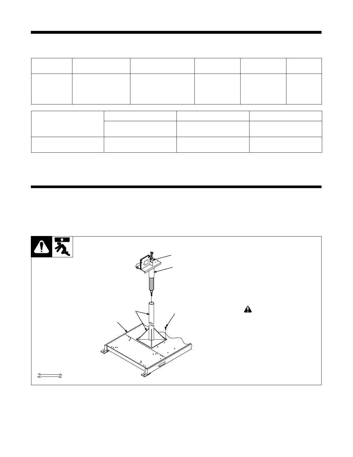
4-2. Installing Swivel Into Pipe Post
ST-152 268-B
1 Swingpak Base or CBC Cart
2 Pipe Post With Base
3 Steel Bolt
Secure as shown using as a mini-
mum 1/2 in. diameter SAE grade 5
steel bolts.
4 Swivel Assembly
Insert into pipe post. Lubricate
swivel.
5 Safety Collar
! Do not remove until
instructed to.
1
2
3
4
5
3/4 in.
Tools Needed:
OM-252 045 Page 12
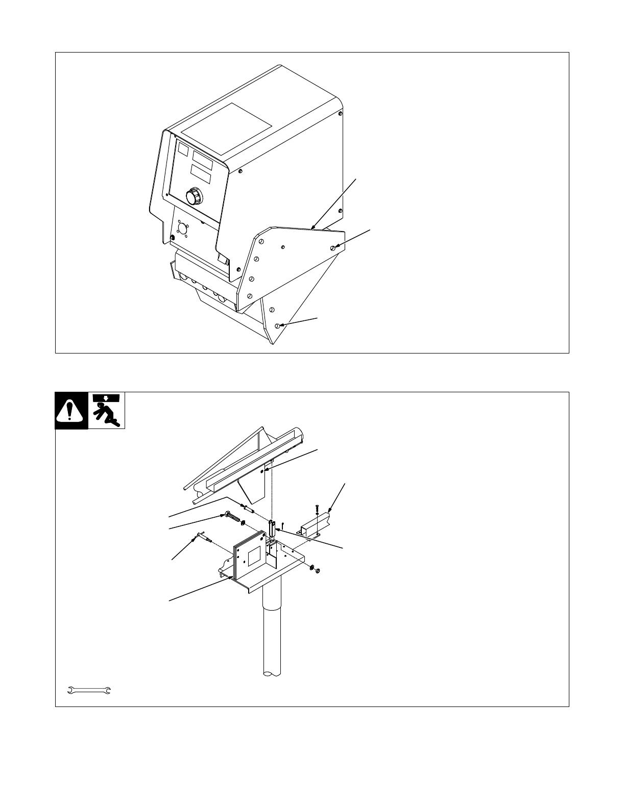
4-3. Adjusting Control Tilt Bracket
805 413-A
1 Tilt Bracket
2 Rear Pivot Screw
3 Front Screw
Loosen rear pivot screw. Remove
front screw. Pivot control down-
ward to desired viewing angle. Re-
place and tighten front screw. Tight-
en pivot screw.
1
2
3
4-4. Installing Boom And Reel Support
142 596-D
1 Swivel Plates
2 Yoke
Remove hardware from swivel
plates and yoke.
3 Boom
Set boom into swivel as shown.
4 Yoke Pin
Install pin through yoke. Install cot-
ter pin and spread ends.
5 Bolt
Install bolt, tighten hardware, and
back bolt off one half turn.
6 Locking Knob
Install locking knob but do not
tighten.
7 Reel Support
Install reel support.
3
4
5
6
7
1
2
3/8, 3/4 in.
Tools Needed:

OM-252 045 Page 13
4-5. Installing Wire Guide Extension
152 323-B
1 Wire Guide Fitting
2 Bolt
3 Monocoil Liner
4 Wire Guide Extension
Tighten bolt to secure liner in wire
guide fitting. Do not overtighten bolt
and crush liner.
1
2
3
4
3/8 in.
Tools Needed:
805 414-B
1 Welding Power Source
2 Remote 14 Connection
3 Positive (+) Weld Output
Cable
4 Negative (−) Weld Output
Cable
5 Workpiece
6 Weld Control (Ref)
7 Boom
8 Gun
9 Trigger Connection
10 Swivel
11 Pipe Post And Base
12 Gas Hose
13 Gas Supply And Regulator
(Customer Supplied)
. Shielding gas pressure not to
exceed 100 psi (689 kPa).
4-6. Equipment Connection Diagram
1
4
5
6
7
8
10
11
12
13
2
3
9

OM-252 045 Page 14
Ref. 805 415-B
1 Interconnecting Cable
Receptacle
2 Interconnecting Cable
3 14-Pin Receptacle
4-7. Control Box Connections
1
2
3
4-8. 14-Pin Plug Information
Pin* Pin Information
AJ
B
K
I
C
L
NH
D
M
G
E
F
A 24 volts AC with respect to socket G.
B Contact closure to A completes 24 volts AC contactor control circuit.
G Circuit common for 24 volts AC circuit.
C +10 volts DC output to remote control with respect to socket D.
D Remote control circuit common.
E 0 to +10 volts DC input command signal from remote control with respect to socket D.
H Voltage feedback; 0 to +10 volts DC, 1 volt per 10 arc volts.
F Current feedback; 0 to +10 volts DC, 1 volt per 100 amperes.
*The remaining pins are not used.

OM-252 045 Page 15
4-9. Removing Safety Collar And Adjusting Boom
1 Locking Knob
Tighten knob to prevent boom
movement. Loosen knob to allow
boom movement. Change knob po-
sition to limit upward movement.
Pull boom down slightly and remove
safety collar. Boom should balance
in any position from horizontal to 60
degrees above horizontal. If neces-
sary, adjust boom as follows:
2 Threaded Rod
3 Jam Nut
Loosen jam nut and turn threaded
rod until boom balances. Tighten
jam nut. Be sure several full threads
are through yoke to prevent boom
falling.
4 Yoke
Retain safety collar for use in disas-
sembling or moving boom.
Ref. 152 323-B
Increasing Spring
Pressure For A
Heavy Gun
Decreasing Spring
Pressure For A
Light Gun
4
3
2
Tools Needed:
1-1/8 in.
Rod
Rod
1
2
4
3
4-10. Wire Type, Size, And Feed Speed Capability Table
Motor Speed Wire Type Wire Size Feed Speed Capability
Standard All .023 To 5/64 in. (0.6 To 2 mm) 50 To 780 ipm (1.3 To 19.8 mpm)
Standard All 3/32 To 7/64 in. (2.4 To 2.8 mm) 50 To 700 ipm (1.3 To 17.8 mpm)
Standard All 1/8 in. (3.2 mm) 50 To 300 ipm (1.3 To 7.6 mpm)
Optional High
Speed
All .023 To 5/64 in. (0.6 To 2 mm) 92 To 1435 ipm (2.3 To 36.4 mpm)
OM-252 045 Page 16
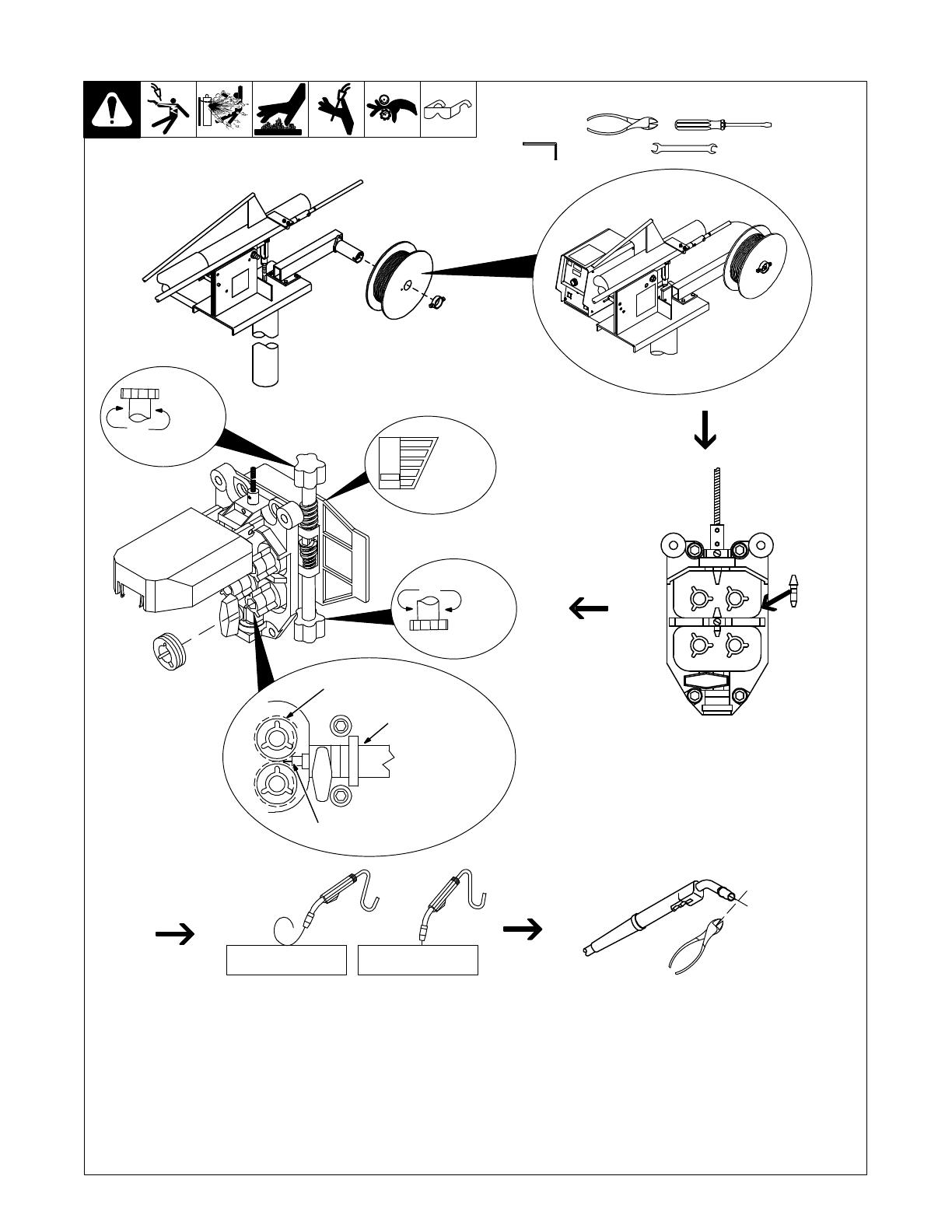
4-11. Installing And Threading Welding Wire
Install wire spool. Ad-
just tension nut so
wire is taut when wire
feed stops.
Install wire guide.
Pressure
Adjust
Install drive rolls.
NONCONDUCTIVE
SURFACE
NONCONDUCTIVE
SURFACE
No Wire Slip Wire Slips
152 648-A / 802 865 / 802 966 / Ref. 137 391-A / 802 954 / Ref. S-0627-A / 805 416-A
Tools Needed:
3/16, 5/64 in.
15/16, 3/8 in.
. Be sure that outlet cable has proper size
liner for the welding wire size. When
installing gun, position liner
extending from outlet wire guide as
close as possible to drive rolls without
touching.
Install gun. Lay gun cable out straight. Cut off
end of wire. Push wire through guides up to
drive rolls; continue to hold wire. Press Jog
button to feed wire out gun.
. For soft wire or small diameter stainless
steel wire, reduce drive roll pressure on
the rear roll to half that of the front rolls.
. To adjust drive roll pressure, hold nozzle
about 2 in. (51 mm) from nonconductive
surface and press gun trigger to feed wire
against surface. Tighten knob so wire
does not slip. Do not overtighten. If con-
tact tip is completely blocked, wire should
slip at the feeder (see pressure adjust-
ment above).Cut wire off. Close cover.
Drive Rolls
End Of Liner
Gun Cable
Pressure
Adjust
Pressure
Indicator
Scale

OM-252 045 Page 17
SECTION 5 − MAINTENANCE
5-1. Routine Maintenance
! Disconnect power before maintaining.
3 Months
Replace
unreadable
labels.
Clean and
tighten
weld
terminals.
Repair or
replace
cracked
weld
cable.
Check
14-pin cord.
Check gas
hose and
fittings.
Check gun
cable.
Replace
cracked
parts.
6 Months
Blow out or vacuum
inside. During heavy
service, clean
monthly.
Or
Clean
drive rolls.
5-2. Troubleshooting
! Disconnect power before troubleshooting.
Trouble Remedy
Wire feeds, shielding gas flows, but
electrode wire is not energized.
Check interconnecting cord connections. If secure, check cord for continuity and repair or replace
(see Sections 4-6 and 4-7).
Wire feeder is on, display does not light
up, motor does not run, gas valve and
welding power source contactor do not
pull in.
Check and reset circuit breaker at welding power source.
Electrode wire feeding stops or feeds
erratically during welding.
Check gun trigger connection. See gun Owner’s Manual.
Check gun trigger. See gun Owner’s Manual.
Readjust hub tension and drive roll pressure (see Section 4-11).
Change to correct size drive roll (see Table 6-1).
Clean or replace dirty or worn drive roll.
Incorrect size or worn wire guides.
Replace contact tip or liner. See gun Owner’s Manual.
Remove weld spatter or foreign matter from around nozzle opening.
Have Factory Authorized Service Agency check drive motor or motor control board PC1.
Motor runs slowly. Check for correct input voltage.
Wire feeder power is on, displays light
up, but unit is inoperative.
Check welding gun trigger leads for continuity, and repair leads or replace gun.

OM-252 045 Page 18
SECTION 6 − PARTS LIST
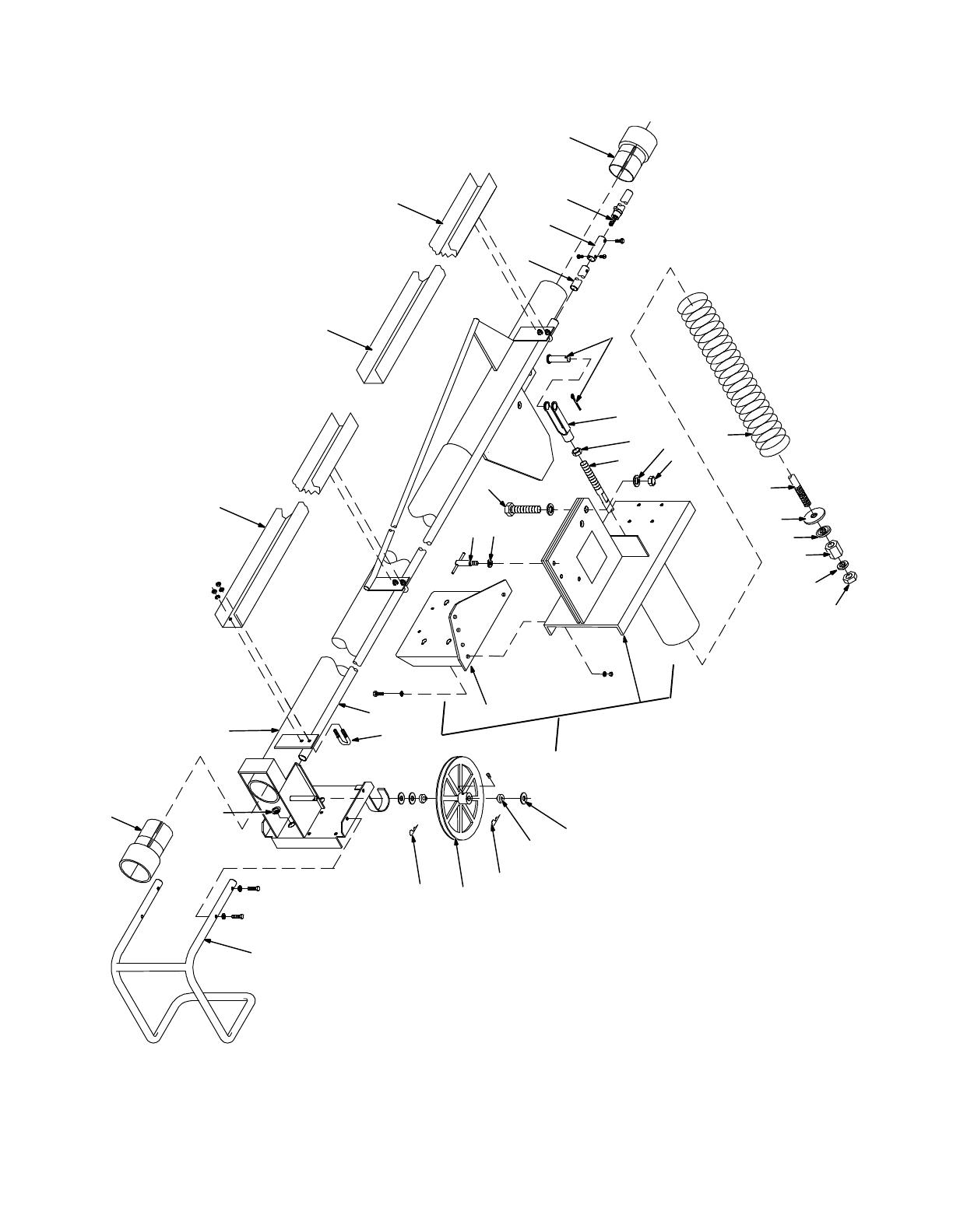
805 419-C
. Hardware is common and
not available unless listed.
1
2
3
4
5
6
6
7
8
9
Fig 6-4
10
11
Fig 6-2
1
12
13
14
15
16
17
18
19
21
22
23
24
25
26
27
28
16
30
31
20
29
32
33
34
Fig 6-3
Figure 6-1. Main Assembly

OM-252 045 Page 19
Quantity
Description
Part
No.
Dia.
Mkgs.
Item
No.
Model
12
16
Figure 6-1. Main Assembly
8
1 201 319 Cable, Interconnecting (Includes) 1 1... ............. .. ..................... ....
1 201 320 Cable, Interconnecting (Includes) 1... ............. .. ..................................
PLG37,38 047 636 Connector & Pins 2 2 2...... .. .... ................................. .... ....
079 739 Connector, Circ Clamp Str Rlf Sz 17.20 2 2 2................... .... .............. .... ....
163 520 Cable, Port No. 18-14 11/C (Order By Ft) 17Ft 17Ft 21Ft................... .... ............ ..
2 139 600 Hose, Gas 1 1... ............. .. ......................................... ....
2 139 599 Hose, Gas 1... ............. .. ......................................................
3 600 324 Cable, Weld Cop Strd No. 4/0 (Order By Ft) 26Ft 26Ft 30Ft... ............. .. ............ ..
4 149 884 Bracket, Spring Retaining 1 1... ............. .. ........................... ....
4 080 947 Bracket, Spring Retaining 1... ............. .. ........................................
5 132 053 Screw, Cap Stl Hexhd .375-16 X 1.500 Lg 4 4 4... ............. .. ............. .... ....
6 602 243 Washer, Flat Stl Std .375 8 8 8... ............. .. ............................ .... ....
7 602 213 Washer, Lock Stl Split .375 4 4 4... ............. .. .......................... .... ....
8 601 872 Nut, Stl Hex Full .375-16 4 4 4... ............. .. ............................ .... ....
9 Figure 6-4 Support, Hub & Reel 1 1 1... ............ .. ................................ .... ....
10 149 838 Pipe Post, 4Ft W/Base (Optional)... ............. .. .....................
10 149 839 Pipe Post, 6Ft W/Base (Optional)... ............. .. .....................
11 Figure 6-2 Boom Assembly 1 1 1... ............ .. .................................... .... ....
12 RC37 047 637 Connector & Sockets 1 1 1... .. .... .. ............................... .... ....
13 PLG46 115 090 Connector & Pins 1 1 1... .. .... .. ................................... .... ....
14 PLG44 167 640 Connector & Pins & Sockets 1 1 1... .. ... .. ......................... .... ....
15 PLG4 136 810 Connector & Sockets 1 1 1... .. .... .. ............................... .... ....
16 203 314 Cable, Trigger (Includes) 1... ............. .. .........................................
RC13 080 328 Connector W/Sockets, Free Hanging 1 1 1........ .... .... ................ .... ....
079 531 Connector, Circ Clamp Str Rlf Size 11 Amp 206358-2 2 2 2................... .... .. .... ....
604 571 Cable, 18/4 2Ft 2Ft 2Ft................... .... ...................................... . ..
PLG6 115 094 Connector & Sockets 1 1 1........ ..... .... .............................. .... ....
17 PLG5 131 204 Connector & Sockets 1 1 1... .. .... .. ............................... .... ....
18 PLG45 131 203 Connector & Sockets 1 1 1... .. ... .. ............................... .... ....
19 605 227 Nut, Nyl Hex Jam .750Npst 1 1 1... ............. .. .......................... .... ....
20 211 989 Fitting, W/Screen 1 1 1... .............. .. ................................... .... ....
21 GS1 228 035 Valve, 34VDC 1way .750−14 Thd 2mm Orf 100PSI 1 1 1... ... ..... .. ..... .... ....
134 834 Hose, SAE .187 Id X .410 Od (Order By Ft) 2Ft 2Ft 2Ft................... .. ............ . ..
22 139 265 Cover, Motor & Components 1 1 1... ............. .. ......................... .... ....
23 156 243 Clamp, Motor Top 1 1 1... ............. .. .................................. .... ....
24 159 360 Insulator, Screw Machine 4 4 4... ............. .. ............................ .... ....
25 145 639 Strip, Buna N Compressed Sheet .062 X 4.000Sq 1 1 1... ............. .. ...... .... ....
26 201 773 Drive Assy., Wire (W/Tach) Figure 6-3 (Optional) 1 1 1... ............. .. ....... .... ....
26 201 774 Drive Assy., Wire (H/Speed w/Tach) Figure 6-3 (Optional) 1 1 1... ............. .. .... ....
27 157 295 Guide, Monocoil 1 1 1... ............. .. .................................... .... ....
28 604 612 Screw, Set Stl Sch 8-32 X .125 Cup Point 2 2 2... ............. .. ............. .... ....
29 082 050 Liner, Monocoil Inlet Wire 1 1 1... ............. .. ............................ .... ....
30 159 646 Clamp, Motor Base 1 1 1... ............. .. ................................. .... ....
31 159 647 Insulator, Motor Clamp 1 1 1... ............. .. .............................. .... ....
32 237 442 Channel, Harness Wire 85.500 in 2.188 in Wide 1... ............. .. ........
33 220 330 Channel, Harness Wire 67.500 in 2.093 OD Wide 1 1... ............. .. ............. ....
34 220 331 Channel, Harness Wire 67.500 in 2.125 ID Wide 1 2... ............. .. .............. ....
Note: When ordering Control Box contact factory service department for proper number.
To maintain the factory original performance of your equipment, use only Manufacturer’s Suggested
Replacement Parts. Model and serial number required when ordering parts from your local distributor.
OM-252 045 Page 20
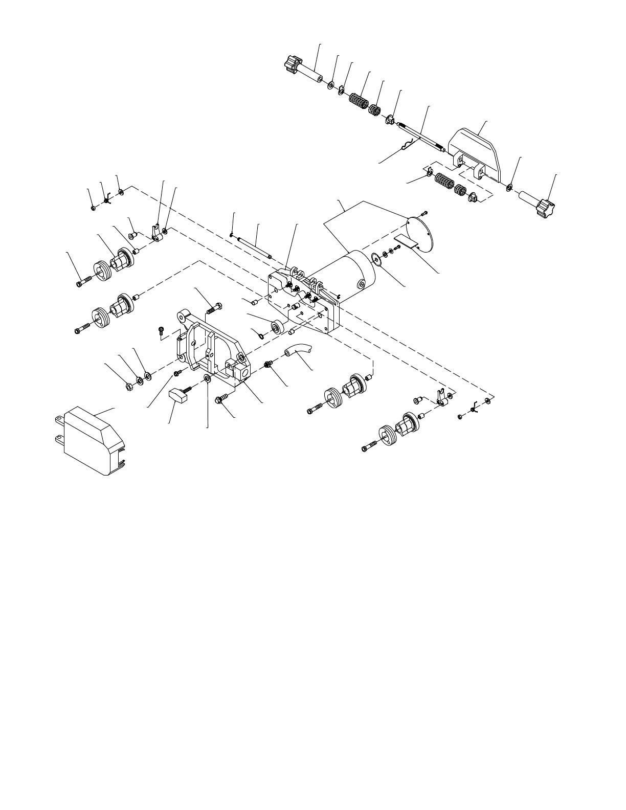
142 601-H
. Hardware is common and
not available unless listed.
1
2
3
4
5
8
9
10
11
12
13
10
14
15
16
17
9
19
18
25
26
28
27
29
24
23
21
22
20
31
32
33
7
27
6
30
Figure 6-2. Boom Assembly

OM-252 045 Page 21
Quantity
Description
Part
No.
Item
No.
Model
12 16
Figure 6-2. Boom Assembly (Figure 6-1 Item 11)
8
1 000 527 Plug, 0.875 Inch 1 1 1... ..... .. ............................................ .... ....
2 236 032 Boom, Single 1... ..... .. ...............................................
2 159 991 Boom, Single 1... ..... .. .....................................................
2 159 989 Boom, Single 1... ..... .. ............................................................
3 237 740 Guide, Wire 1... ..... .. ................................................
3 079 665 Guide, Wire 1... ..... .. ......................................................
3 080 811 Guide, Wire 1... ..... .. .............................................................
4 079 664 Guide, Wire Inlet 1 1 1... ..... .. ............................................ .... ....
5 139 633 Liner, Monocoil 3/32-1/8 Wire X 15.687 1 1 1... ..... .. ........................ .... ....
6 241 229 Bushing, Plastic 1 1 1... ..... .. ............................................ .... ....
7 073 742 Pin, Clevis .750 Od X 2.156 Lg 1 1 1... ..... .. ............................... .... ....
8 073 741 Clevis, .812 Yoke 6.062 Lg .750-16Thd 1 1 1... ..... .. ........................ .... ....
9 079 029 Nut, Stl Hex Full Fnsh .750-16 2 2 2... ..... .. ................................ .... ....
10 075 462 Shaft, Boom Counterbalance 1 1 1... ..... .. ................................. .... ....
11 602 250 Washer, Flat Stl SAE .750 2 2 2... ..... .. .................................... .... ....
12 079 020 Nut, Stl Hex Elastic Stop .750-16 1 1 1... ..... .. .............................. .... ....
13 149 858 Spring, Cprsn 3.750 Od X .625 Wire X 36.000 1 1... ..... .. .................. ....
13 080 723 Spring, Cprsn 3.750 Od X .687 Wire X 33.750 1... ..... .. ...............................
14 150 258 Retainer, Spring 1 1 1... ..... .. ............................................ .... ....
15 024 605 Bearing, Ball Thr Sgl Row .750 X 1.625 X .625 1 1 1... ..... .. .................. .... ....
16 075 101 Nut, Stl Hex Special .750-16 X 1.250 1 1 1... ..... .. .......................... .... ....
17 079 030 Washer, Lock Stl Ext Tooth .750 1 1 1... ..... .. .............................. .... ....
18 +174 754 Base, Swivel Boom (Includes) 1 1 1... .... .. ................................ .... ....
080 157 Fitting, Grease 1/8Npt 1 1 1........... .... ..................................... .... ....
19 174 688 Bracket, Mtg Control Tilt 1 1 1... ..... .... .................................... .... ....
142 804 Label, Swingarc Caution Heavy Spring 1 1 1........... .. ......................... .... ....
134 327 Label, Warning General Precautionary 1 1 1........... .. ......................... .... ....
20 073 666 Bolt, Mach Stl Hexhd .750-16 X 2.750 1 1 1... ..... .. ......................... .... ....
21 047 224 Knob, T-Bar .500-13 Thd 1 1 1... ..... .. ..................................... .... ....
22 602 246 Washer, Flat Stl Std .500 1 1 1... ..... .. ..................................... .... ....
23 236 033 Pipe, Plstc .500 X 85.750 1... ..... .. ....................................
23 079 667 Pipe, Plstc .500 X 133.750 1... ..... .. .........................................
23 080 812 Pipe, Plstc .500 X 181.750 1... ..... .. ................................................
24 079 632 Bolt, U Stl .250-20 X .875 Wide X 1.375 Deep 4 4 5... ..... .. .................. .... ....
25 602 243 Washer, Flat Stl Std .375 3 3 3... ..... .. ..................................... .... ....
26 079 622 Washer, Shldr .381 Id X .750 Od 2 2 2... ..... .. .............................. .... ....
27 010 313 Pin, Cotter Hair .072 X 1.437 2 2 2... ..... .. ................................. .... ....
28 079 621 Pulley, V Sgl Grv 1 1 1... ..... .. ............................................ .... ....
29 139 336 Guard, Motor Protector 1 1 1... ..... .. ...................................... .... ....
149 332 Clamp, Hose .405 − .485Clp 2 2 2........... .. .................................. .... ....
30 251 898 Bushing, Plastic 1 1 1... ..... .. ............................................ .... ....
31 220 331 Channel, Harness Wire 67.500 in 2.125 ID Wide 1 2... ..... .. ...................... ....
32 220 330 Channel, Harness Wire 67.500 in 2.093 OD Wide 1 1... ..... .. ..................... ....
33 237 442 Channel, Harness Wire 85.500 in 2.188 in Wide 1... ..... .. .................
+When ordering a component originally displaying a precautionary label, the label should also be ordered.
To maintain the factory original performance of your equipment, use only Manufacturer’s Suggested
Replacement Parts. Model and serial number required when ordering parts from your local distributor.
/