Velleman Exciter 250 User manual
- Category
- Stroboscopes & disco lights
- Type
- User manual
This manual is also suitable for

VDP250SC6M – 'EXCITER 250' 6-CHANNEL PROFESSIONAL SCANNER
1. Introduction & Features
To all residents of the European Union
Important environmental information about this product
This symbol on the device or the package indicates that disposal of the device after its lifecycle could harm
the environment.
Do not dispose of the unit (or batteries) as unsorted municipal waste; it should be taken to a specialised
company for recycling.
This device should be returned to your distributor or to a local recycling service.
Respect the local environmental rules.
If in doubt, contact your local waste disposal authorities.
Thank you for having chosen a HQ-POWER 250W six channel scanner. You will see you have acquired a powerful
and versatile device. The VDL250SC6M features 6 DMX channels, creating a fast moving effect. Unpack the device.
Please read the manual thoroughly before bringing this device into service. Please check carefully that there is no
damage caused by transportation. Should there be any, consult your dealer and don’t install this device.
Every person involved with the installation, operation and maintenance of this device has to be qualified and carefully
follow the instructions of this manual.
Features
• 7 colours + white + rainbow effect in both directions
• 7 gobos + open + blackout + shutter
• Gobo rotation
• Strobe (1-10 Hz)
• DMX control, music control and master/slave control
• Fuzzy-sound control: program continues automatically even during periods without music
• Digital display
• Manual focus
2. Safety Instructions
Be very careful during the installation: touching live wires can cause life-threatening electroshocks.
Do not touch the device during operation as the housing heats up.
Keep this device away from rain and moisture.
Unplug the mains lead before opening the housing.
• This device has left the factory in perfect condition. In order to maintain this condition and to ensure a safe
operation, it is absolutely necessary for the user to follow the safety instructions and warning notes written in this
user manual.
• Damage caused by disregard of certain guidelines in this manual is not covered by the warranty and the dealer
will not accept responsibility for any ensuing defects or problems.
• Do not switch the device on immediately after it has been exposed to changes in temperature. Protect the device
against damage by leaving it switched off until it has reached room temperature.
• Make sure that the available voltage does not exceed the voltage stated in the specifications of this manual.
• Do not crimp the power cord and protect it against damage. Have an authorised dealer replace it if necessary.

VDP250SC6M VELLEMAN
2
• Disconnect the device from the mains to clean it or when it is not in use. Handle the power cord by the plug only.
• Caution ! Never look directly into the light source, as sensitive persons may suffer an epileptic shock.
• Please be aware that damages caused by manual modifications to the device are not subject to warranty.
• Keep away from children and non-professionals.
3. General Guidelines
• This device is a lighting effect for professional use on stages, in discotheques, theatres, etc. This fixture is only
allowed to be operated with and alternating current of max. 230VAC/50Hz and was designed for indoor use only.
• Lighting effects are not designed for permanent operation. Consistent operation breaks will ensure that the device
will serve you for a long time without defects.
• Do not shake the device. Avoid brute force when installing or operating the device.
• When choosing the installation spot, please make sure that the device is not exposed to extreme heat, moisture
or dust. The minimum distance between light-output from the fixture and the illuminated surface must be more
than 0.5 meter.
• Always fix the fixture with an appropriate safety cable (VDLSC7 or VDLSC8).
• Make sure never to install the device in a place that exceeds the ambient temperature T
a
(see technical
specifications at the end of this user manual).
• Operate the device only after having familiarized yourself with its functions. Do not permit operation by persons
not qualified for operating the device. Most damages are the result of unprofessional operation.
• Please use the original packaging if the device is to be transported.
• For safety reasons, please be aware that all modifications on the device are forbidden. Furthermore, any other
operation may lead to short-circuit, burns, electric shock, lamp explosion, crash, etc. If this device will be operated
in any way different to the one described in this manual, the product may suffer damages and the guarantee
becomes void.
4. Installation
a) Lamp
• Only fit or replace a lamp when the device is unplugged from the mains.
• The lamp has to be replaced when it is damaged or deformed.
• Let a lamp cool down before replacing it as the temperature of a lamp can reach 700°C during operation. Also, do
not switch the lamp back on within 10 minutes after having turned it off.
• Do not touch the lamp with your bare hands. Use a cloth to insert or remove it.
• Do not install lamps with a higher wattage than what this device was designed for.
• For the installation, you need a 90V / 250W MSD GY9.5 lamp:
order code : LAMP250MSD or LAMP250MSD/2
1) Unscrew the 2 screws marked with X and Y on the back of the housing, holding the plate where the lamp is
underneath.
2) Carefully insert the lamp into the socket. Please remember there is only one way to insert the lamp. Gently
slide the lamp and its lamp holder back into place and fasten the 2 screws.
3) On the access plate there are 3 small screws marked A, B and C which are used to adjust the lamp holder in
the lamp housing. You can adjust the 3 screws to fine-tune the position of the lamp to get the maximum light
output.
• Please remember the lamp is not a hot-restrike type, you must wait for approximately 10 minutes after having
turned off the lamp before you can turn it back on again.
Remark: Do not operate the device when the glass pane is off.

VDP250SC6M VELLEMAN
3
b) Fuse
• Only fit or replace a fuse when the device is unplugged from the mains.
• If the lamp burns out, chances are you will need to replace the fuse as well.
• Replace a blown fuse with a fuse of the same type and ratings.
• For the installation, you need one 5A / 250VAC 5 x 20 mm fuse:
order code : FF5N
1) Remove the fuse holder cap on the rear panel underneath the power connector.
2) Remove the old fuse and replace it by the new one with the same technical specifications.
3) Replace the fuse holder cap in the housing.
c) Mounting the Device
• Have the device installed by a qualified person, respecting EN 60598-2-17 and all other applicable norms.
• The installation of the effect has to be built and constructed in a way that it can hold 10 times the weight for 1 hour
without any harming deformation.
• The installation must always be secured with a secondary safety attachment, e.g. an appropriate safety cable
(VDLSC7 or VDLSC8).
• Never stand directly below the device when mounting, removing or servicing the fixture.
The operator has to make sure the safety relating and machine technical installations are approved by an expert
before taking the device into operation for the first time. These installations have to be approved by a skilled
person once a year.
• The effect should be installed outside areas where persons may reach it, walk by or be seated.
• Overhead mounting requires extensive experience, including amongst others calculating working load limits,
installation material being used, and periodic safety inspection of all installation material and the device. If you
lack these qualifications, do not attempt the installation yourself. Improper installation can result in bodily injury.
• Before mounting make sure that the installation area can hold a minimum point load of 10 times the device’s weight.
• When installing the device, make sure there is no highly inflammable material within a distance of min. 0.5m.
• Adjust the desired inclination angle via the mounting bracket and fix the bracket screws tightly.
• The electric connection may only be carried out by a qualified technician.
• Connect the fixture to the mains with the power plug. In general, lighting effects should not be connected to
dimming packs.
• The installation has to be approved by an expert before the device is taken into service.
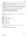
5. Operating Instructions
The fixture has 8 modes of operation which will be shown on the display. Select the corresponding mode by means
of the MODE button and the UP and DOWN buttons.
001 D : DMX mode
N1N N : music controlled (master mode)
N2N N : auto program (master mode)
N3N N : standby (master mode)
S1S S : slave 1 (slave mode)
S2S 2 : slave 2 (slave mode)
S3S S : slave 3 (slave mode)
S4S S : slave 4 (slave mode)
Please remember when you change modes, you have to switch the device off and back on again.

VDP250SC6M VELLEMAN
4
a) Music Controlled Mode
The fixture will react to the music through the built-in microphone.
b) Master/Slave Mode
If you have several fixtures, you can chain them together and let them make synchronous movement, controlled by
the master device.
The master unit will drive all slave units. Connect the master and slave units using the provided DMX cable.
When in this mode, the built-in microphone (when in music mode) or auto program function of the master machine
controls all fixtures and they will change colour rhythmically and synchronously.
c) Program Mode
To make the fixture run its internal program continuously.
d) DMX Mode
All fixtures should be given a DMX start address when using a DMX signal, so that the correct fixture responds to the
correct control signals. This digital start address is the channel number from which the fixture starts to “listen” to the
digital control information being sent out from the DMX controller. The allocation of this start address is achieved by
setting the correct number by means of the DIP switch located on the back of the VDP250SC6M.
As you prefer, you can set the same start address for all or a group of fixtures or select a different one for each
fixture individually.
If you set the same address, all the units will start to “listen” to the same control signal from the same channel
number. In other words: changing the settings of one channel will affect all the fixtures simultaneously.
If you set a different address, each unit will start to “listen” to the channel number you have set, based on the quantity
of control channels of the unit. In other words: changing the settings of one channel will affect only the selected
fixture.
In the case of the VDP250SC6M, which is a 6 channel fixture, you will have to set the start address of the first unit to
1, the second unit to 7 (1 + 6), the third to 13 (7 + 6), and so on.
Make sure you are in DMX mode. Select the correct start address by means of the UP and DOWN buttons.
The LED next to the DIP switches indicates the status of the DMX signal.
LED flashing: DMX signal present
LED steady on: no input DMX signal
e) Channel Configuration
CHANNEL 1 : Pan
CHANNEL 2 : Tilt
CHANNEL 3 : Colour wheel
CHANNEL 4 : Gobo wheel
CHANNEL 5 : Gobo rotation
CHANNEL 6 : Strobe

VDP250SC6M VELLEMAN
5
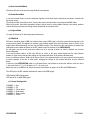
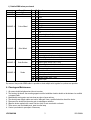
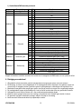
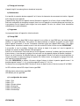
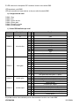
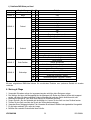
f) Detailed DMX values per channel
Description From
To
Function
CHANNEL 1
Pan 0 255
8 bit
CHANNEL 2
Tilt 0 255
8 bit
0 18
white
18 35
dark blue
36 53
pink
54 71
light green
72 89
orange
90 107
light blue
108 126
yellow
127 red
128 191
forward rainbow effect
CHANNEL 3
Colour Wheel
192 255
Backward Rainbow effect
0 15
open
16 31
32 47
48 63
64 79
80 95
96 111
112 127
128 191
forward gobo cycle (slow -> fast)
CHANNEL 4
Gobo Wheel
192 255
backward gobo cycle (slow –> fast)
0 15
no rotation
16 135
forward gobo rotation (fast-> slow)
CHANNEL 5
Gobo Rotation
136 255
backward gobo rotation (slow -> fast)
0 5 shutter closed
6 128
dimmer control
129 131
reset (after 3-5 seconds)
132 139
shutter open
140 199
strobe (slow -> fast)
200 249
random strobe (slow -> fast)
CHANNEL 6
Strobe
250 255
shutter open
By means of the provided DMX cable it is possible to chain multiple units together for synchronous operation.
6. Cleaning and Maintenance
1. All screws should be tightened and free of corrosion.
2. The housing, the lenses, the mounting supports and the installation location should not be deformed or modified
or tampered with.
3. Mechanically moving parts must not show any signs of wear and tear.
4. The electric power supply cables must not be damaged. Have a qualified technician check the device.
5. Disconnect the device from the mains prior to maintenance activities.
6. Wipe the device regularly with a moist, lint-free cloth. Do not use alcohol or solvents.
7. There are no user-serviceable parts, apart from the lamp.
8. Contact your dealer for spare parts if necessary.
Page is loading ...
Page is loading ...
Page is loading ...
Page is loading ...
Page is loading ...
Page is loading ...
Page is loading ...
Page is loading ...
Page is loading ...
Page is loading ...
Page is loading ...
Page is loading ...
Page is loading ...
Page is loading ...
Page is loading ...
Page is loading ...
Page is loading ...
Page is loading ...
Page is loading ...
Page is loading ...
Page is loading ...

VDP250SC6M VELLEMAN
27
7. Technische Daten
Stromversorgung: max. 230VAC, 50Hz
Stromverbrauch: max. 260W
Sicherung: 5A, 250VAC (5 x 20mm)
Abmessungen: 525 x 300 x 150 mm
Gewicht: 15 kg
Lampe: 250W / 90V MSD GY9.5
Max. UmgebungstemperaturT
a
: 45° C
Max. Gehäusetemperatur T
a
: 60° C
Signal: internationale Norm DMX 512
Alle Änderungen vorbehalten.
-
 1
1
-
 2
2
-
 3
3
-
 4
4
-
 5
5
-
 6
6
-
 7
7
-
 8
8
-
 9
9
-
 10
10
-
 11
11
-
 12
12
-
 13
13
-
 14
14
-
 15
15
-
 16
16
-
 17
17
-
 18
18
-
 19
19
-
 20
20
-
 21
21
-
 22
22
-
 23
23
-
 24
24
-
 25
25
-
 26
26
-
 27
27


Velleman Exciter 250 User manual
- Category
- Stroboscopes & disco lights
- Type
- User manual
- This manual is also suitable for
Ask a question and I''ll find the answer in the document
Finding information in a document is now easier with AI
in other languages
- français: Velleman Exciter 250 Manuel utilisateur
- español: Velleman Exciter 250 Manual de usuario
- Deutsch: Velleman Exciter 250 Benutzerhandbuch
- Nederlands: Velleman Exciter 250 Handleiding
Related papers
-
Velleman HQ POWER VDP250ML User manual
-
Velleman VDL4DL Datasheet
-
HQ Power VDL5DL2 User manual
-
 HQ Power HQ-Power VDPLW1028 User manual
-
 HQ Power VDL20ST User manual
-
-
HQ Power Arazu II User manual
-
Velleman VDL360RL2 User manual
-
HQ Power Mini strobe 45W Specification
-


Other documents
-
 HQ Power VDLPCS User manual
-
HQ Power VDL20UV User manual
-
 HQ Power VDP250SC6 Datasheet
-
 HQ Power VDL1500ST User manual
-
 HQ Power VDL20ST2 User manual
-
 HQ Power VDL400AL Quick start guide
-
 HQ Power VDL75ST User manual
-
 HQ Power VDP250SC4EHJ User manual
-
 HQ Power HQLE10036 User manual
-
 HQ Power VDP250MGD2 User manual


