Multiplex Technology COCKPIT SX M-LINK Operating instructions
- Category
- Remote controlled toys
- Type
- Operating instructions
This manual is also suitable for
Page is loading ...
Page is loading ...
Page is loading ...
Page is loading ...
Page is loading ...
Page is loading ...
Page is loading ...
Page is loading ...
Page is loading ...
Page is loading ...
Page is loading ...
Page is loading ...

MULTIPLEX Modellsport GmbH & Co.KG • Westliche Gewerbestraße 1 • D-75015 Bretten (Gölshausen) • www.multiplex-rc.de Page 1/9
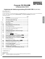
Supplementary Cockpit SX operating instructions for Cockpit SX M-LINK # 85 5327 (09-08-13/NSCH) • Errors and omissions excepted • © MULTIPLEX 2009
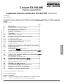
ENGLISH
COCKPIT SX M-LINK
Software version V2.10
Supplementary COCKPIT SX Operating Instructions (35/40 MHz)
Dear customer,
Dear fellow-modeller,
This supplement to the C
OCKPIT SX operating instructions covers the points which have been changed with the intro-
duction of our new 2.4 GHz M-LINK transmission system for the C
OCKPIT SX M-LINK.
In detail these are:
Page
2. Introduction.................................................................2
3.2. New menus for range checking.......................................................2
6. CE conformity declaration .........................................3
7. Specification................................................................3
9. The transmitter............................................................4
9.5.1. New transmitter aerial......................................................................4
10. New sequence when first using the system ............4
10.2. The binding procedure.....................................................................4
10.3. Switching on (normally)...................................................................5
10.4. What to do if THRO>0” appears on the screen?.........................5
10.5. The RF status indicator (blue LED).................................................6
10.6. General notes..................................................................................6
12. Transmitter settings and information displays........6
12.1. New RESET code............................................................................6
12.2. The INFO displays
New INFO 7 display for RXBATT...................................................7
13. Setting up a new model, model type: EASY.............7
13.7.4. Changing the standard assignment of servo 5 (AILERON) ............7
14. Setting up a new model, model type: ACRO...............
14.5. Activating flight phases
EXPO, flight phase dependent........................................................8
18. Memory management menu: MEMO ..........................8
18.6. Transmitting the Fail-Safe position, menu: SENDFS .....................8
18.7. Activating Fast Response, menu: F-RESP ...................................8
20. Trainer mode operations............................................9
20.2. The COCKPIT SX M-LINK as Pupil transmitter ................................9
21. Accessories, replacement parts................................9
22. Multi-function socket interfaces................................9
We all wish you many hours of pleasure with your system.
Yours - the MULTIPLEX team
Chapter references
Î x. refers to Chapter in the tri-lingual operating instructions (manual)
Î x. refers to Chapter in this supplement

COCKPIT SX M-LINK
MULTIPLEX Modellsport GmbH & Co.KG • Westliche Gewerbestraße 1 • D-75015 Bretten (Gölshausen) • www.multiplex-rc.de Seite 2/9
2. Introduction
We are delighted that you have decided to purchase a
MULTIPLEX C
OCKPIT SX M-LINK radio control system.
You are now the owner of an RC transmitter which is
based on the proven structures of the C
OCKPIT SX on
the one hand, and on the other offers the latest, future-
proof technology in the form of the 2.4 GHz M-LINK
sys-tem and a FLASH processor.
The range of applications extends from simple two-axis
model aircraft right up to demanding four-flap gliders
and aerobatic models. At the same time the software
includes a refined helicopter program for all current ro-
tor systems, catering for the demands even of ex-
perienced model helicopter pilots.
The essential features of the C
OCKPIT SX M-LINK:
• The latest 2.4 GHz M-LINK technology as standard
FHSS (Frequency Hopping Spread Spectrum)
12-bit resolution (3872 steps)
14 / 21 ms servo pulse, switchable
• Telemetry facilities with appropriate receiver
(display / monitor of receiver battery voltage)
• Seven channels
• Eighteen model memories
With unrestricted model names (max. six characters),
Copy and erase functions
• Switchable flight phases with three phases for fixed-
wing model aircraft and four for model helicopters
• Flight phase specific digital trim system with clearly ar-
ranged graphical on-screen display of trim settings, and
audible support
• Modern, ergonomically optimised case design for hand-
held or tray use
• Clearly arranged and grouped menus for simple pro-
gramming
• Plain English (or German) menu system and screen
texts
• Fast, easy programming with the 3-D digi-adjuster
• Two separately controlled timers, one with user-variable
alarm time and audible alarm function
• Transmitter operating hours timer
• Audible battery alarm with user-variable warning
threshold (transmitter battery voltage)
• Modern FLASH processor technology.
Simple update method for new software versions
• Comprehensive set-up and mixer facilities for fixed-wing
model aircraft and model helicopters
• Four pre-programmed model types minimise pro-
gramming effort required
• Selective Trainer mode possible in standard form
• MULTIPLEX multi-function socket fitted as standard, for
use as charge socket, Trainer mode interface, flight
simulator, PC interface
We are sure that you will thoroughly enjoy the facilities
of your C
OCKPIT SX M-LINK as soon as you have
taken a little while to learn how to use it - a period in
which these operating instructions will guide you. You
can look forward to many hours of pleasure in the fas-
cinating hobby of model sport which we all share.
Yours - the MULTIPLEX-Team
3. Safety Notes
3.2. Range checking
Regular range checks are very important, as they help
you to feel confident that the radio control system is
working properly, and enable you to detect changes in
transmission characteristics. Range checking is par-
ticularly important if:
• you are using components for the first time, or
have changed components, or changed their ar-
rangement in the model;
• you are using components in a model which have
previously been involved in a crash;
• you have detected problems when using the sys-
tem.
Important:
• Always carry out the range check with the help of
a friend who can secure and observe the model
(vehicles and boats on the ground).
• Range checking should only be carried out in the
special reduced-power mode (LO POW).
! Never try to operate a model in this mode!
• Major metallic objects (wire fences, cars) will in-
fluence the test results. Keep your distance!
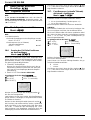
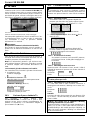
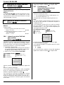
This is the procedure:
1. Switch the transmitter on with the 3-D digi-adjuster
pressed in. The menu LO POW (low power) ap-
pears. Release the 3-D digi-adjuster again.
A brief press on the 3-D digi-adjuster activates
range check mode.
- The blue Status LED glows constantly.
- The screen alternates between LO POW and the
current display.
- A regular warning sound alerts you to the reduced
power setting.
2. Hold the transmitter just as you would when using it
to control a model:
- approx. 1 m above the ground;
- aerial angled at 90° horizontally, and facing right
or left.
3. Model aircraft: place or hold the model in such a
position that the receiving system is about 1 m
above the ground.
Land vehicle or boat: place the model on the
ground or in the water.
Switch the model’s power system off!
4. Switch the receiving system on.
Move one control function (e.g. elevator) constantly
and smoothly. This allows you to see clearly

Supplement to the manual
MULTIPLEX Modellsport GmbH & Co.KG • Westliche Gewerbestraße 1 • D-75015 Bretten (Gölshausen) • www.multiplex-rc.de Seite 3/9
ENGLISH
whether the receiving system responds to your con-
trol commands with clearly defined, smooth move-
ments of the corresponding control surface.
5. Increase the distance between the transmitter and
the model.
Note: changing the model’s attitude
Constantly move (rotate, tip, incline) the model dur-
ing the range check, so that it does not apply to one
flight attitude only.
You have reached the range limit, when the servos no
longer respond distinctly and with constant movement
to your control commands.
The following have a strong influence on range ...
... environmental conditions.
Obstacles which detract from the visual link bet-
ween transmitter and model.
The type and quality of the terrain, and the weather
conditions.
... receiver technology and sophistication.
Technically sophisticated receivers offer greater
range than simple, small, low-cost receivers.
... conditions inside the model.
Aerial deployment, distance from batteries, motors,
ignition systems, metallic / carbon fibre parts all
have an effect on radio range.
Important: read the receiver instructions
For the actual range which should be achieved please
refer to the instructions supplied with the receiver you
are using.
The instructions also include important information re-
garding the installation and optimisation of the receiver
aerial(s).
Important if the model contains a power system:
Carry out the initial range check with the power system
switched off. Repeat the check with the power system
operating (varying throttle settings): there should be lit-
tle difference in the range achieved. If this is not the
case, you need to locate and eliminate the cause of the
interference (the motor itself, the arrangement of the
receiving system components and power supply, vibra-
tion, etc.).
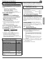
6. CE Conformity Declaration
MULTIPLEX Modellsport GmbH & Co. KG hereby de-
clares that the device described in these instructions
fulfils the requirements of the following harmonised EU
directives:
Electromagnetic Compatibility and Radio Spectrum Matters (ERM)
EN 300 328, EN 300 328-2
EN-301 489-1, EN 301 489-3
Safety
EN 60950-1
A detailed CE Conformity Declaration can be found in
the form of a PDF file on the Internet at www.multiplex-
rc.de. You will find it in the DOWNLOADS area under
PRODUCT INFORMATION.
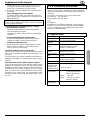
7. Specification
Channel count 7 servo channels
Model memories 18
Transmission
method
2.4 GHz FHSS M-LINK
Frequency
range
2.4000 – 2.4835 GHz or
restricted frequency range
2.4000 – 2.44540 GHz
Servo signal
format
UNI 1.5 ± 0.55 ms
at 100% servo travel
Signal repeat
time
14 ms (Fast Response)
21 ms
Power supply Battery: 7.2 V, 1800 mAh
6 cells, AA-size, NiMH
Current drain ~ 80 mA incl. RF section
Operating tem-
perature range
Storage tem-
perature range
– 15°C to + 55°C
– 20°C to + 60°C
Dimensions
(hand-held)
Length ~ 190 mm
(~ 220 mm with aerial
fitted, angled at 90°)
Width ~ 185 mm
Height ~ 60 mm excl. sticks
and carry handle
Weight
(hand-held)
~ 740 g incl. battery

COCKPIT SX M-LINK
MULTIPLEX Modellsport GmbH & Co.KG • Westliche Gewerbestraße 1 • D-75015 Bretten (Gölshausen) • www.multiplex-rc.de Seite 4/9
9. The transmitter
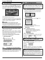
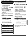
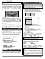
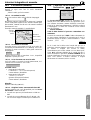
9.5.1. Transmitter aerial
Once installed, the C
OCKPIT SX M-LINK transmitter’s
2.4 GHz aerial can be rotated to the side and tilted up-
wards. When using the transmitter, angle the aerial ap-
proximately at right-angles at the swivel joint, and tilt it
horizontally to left or right (see photo below).
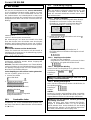
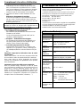
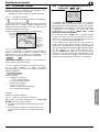
Figure 9.5.1.:
Aerial in operating position; knurled nut
For applications where the model is not directly above
or below the transmitter (this applies in particular to
model cars and boats) the optimum transmitter aerial
position is pointing vertically upwards.
! Important:
Do not point the aerial straight at the model
Never point the aerial directly at the model. For tech-
nical reasons the transmitted signal is at its weakest in
a straight line extending straight out from the aerial.
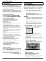
10. First use
Before the transmitter and receiver will work together
they must “learn” each other’s characteristics. This pro-
cedure is known as “binding”.
Note: general information on the subject of binding,
and on fault-finding and correction as part of the bind-
ing procedure, can be found in the instructions supplied
with your MULTIPLEX M-LINK receiver.
Is the receiver already bound to the transmitter?
To check this, use this procedure:
1. Switch the transmitter on
the blue LED flashes
2. Switch the receiver on
Î the yellow LED glows constantly:
Binding required! (Î 10.2.)
Î the yellow LED flashes
Connection successful.
The system is ready for use.
10.1. Charging the transmitter battery
The COCKPIT SX M-LINK is supplied with a partly
charged battery which must be fully charged before the
transmitter is used for the first time. Please see the
notes regarding the transmitter battery (Î 8.).
10.2. The binding procedure
! Note: secure the model !
When the binding procedure is completed successfully,
the system immediately starts working. This could
cause the motor to burst into life, so please secure the
model to avoid property damage or personal injury.
10.2.1. Prepare the transmitter
1. Switch the transmitter on with the 3-D digi-adjuster
pressed in, and then release the 3-D digi-adjuster.
The screen now displays the range check menu L-
RED or LO POW.
The blue LED glows constantly.
2. Turn the 3-D digi-adjuster to the right 3 until you
reach the BIND menu.
Press the 3-D digi-adjuster briefly
r.
You will hear an audible trill, and the blue LED
starts flashing at a high rate.
10.2.2. Switch the receiver on
Switch the receiver on with the SET button
pressed in, and then release the button. The
yellow LED flashes at a high rate.
10.2.3. Successful binding
As soon as the transmitter and receiver have “found”
each other, the flashing rhythm on both units changes.
Receiver:
Transmitter:
! Note: when binding is complete, the transmitter
and receiver are ready for use immediately !
10.2.4. Binding not possible
If the transmitter and receiver continue to flash at a
high rate, binding is not possible.
Receiver:
Transmitter:
Remedy:
Move the transmitter and receiver closer together.
Transmitter output is greatly reduced for the binding
process. (decrease the distance to 50 cm or less.)
! Note: never attempt to carry out a binding pro-
cess with several transmitters simultaneously !
Ensure that no other MULTIPLEX transmitters are op-
erating in binding mode in the immediate vicinity (< 5
m), and that no other models have been prepared for
binding. Systems which are already successfully bound
have no influence on the process.

Supplement to the manual
MULTIPLEX Modellsport GmbH & Co.KG • Westliche Gewerbestraße 1 • D-75015 Bretten (Gölshausen) • www.multiplex-rc.de Seite 5/9
ENGLISH
10.3. Switching on (normally)
In principle the order in which you switch on the trans-
mitter and receiver does not matter. However, it does
no harm to keep to the old habit of:
“First switch the transmitter on, then the receiver”.
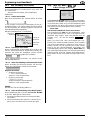
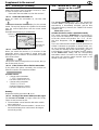
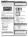
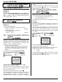
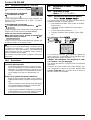
10.3.1. Switch the transmitter on
When you switch the transmitter on, the blue LED
flashes.
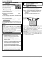
The screen shows the Status display for the selected
model. The top half displays the symbols for the model
type, the current flight phase and the current model
memory.
Example: Model memory 5, model EASY
10.3.2. Switch the receiver on
When you switch the receiver on, it searches for the
transmitter whose code number it stored during the
binding process. If it detects “its” transmitter, the yellow
LED starts to flash.
This process takes no longer than one second; the sys-
tem is then ready for use.
10.3.3. If the receiver fails to find the transmitter
If the yellow LED glows constantly, the receiver has
failed to locate the associated transmitter.
Possible causes:
• Change at the transmitter
F-RESP (Fast Response)
has been switched on or off
• Change at the transmitter
FRANKR / FRANCE
(restricted frequency range)
has been switched on or off
Remedy:
Repeat the binding procedure (Î 10.2.).
10.3.4. Moving to the menus without an RF signal
The C
OCKPIT SX M-LINK no longer offers this facility.
There are two reasons for this:
1. The transmitter cannot interfere with other models
when switched on.
2. The current drain of the transmitter (~ 80 mA) is so
low that the battery does not become discharged
excessively quickly.
10.4. What to do if “THR >0”
appears on the screen?
The C
OCKPIT SX M-LINK warns you if the THROTTLE
control is not in a safe position (idle, or motor OFF). RF
transmission is immediately activated, and the blue
LED starts flashing. However, the THROTTLE channel
remains in the
“Motor OFF” position.
All other functions can be controlled normally.
The control channel for THROTTLE is not released un-
til you move the THROTTLE control on the transmitter
to the Idle / Motor OFF position. The “THR >0” dis-
play then disappears, and the INFO 1 display ap-
pears.
If you are certain that the throttle channel represents no
hazard if released (no propeller on electric motor, mo-
tor not connected, glow motor not running), then you
can switch the warning off with a brief press r on the 3-
D digi-adjuster. However, the throttle channel remains
at the “Motor OFF” setting until the corresponding
transmitter control is moved to the Idle position. Only
then does the receiver output respond again to the
throttle control (stick or slider).
Symbol(s)
f
o
r
model type
Memory No.
Model name
Transmitter bat-
tery voltage
E
A
SY
7.64
V

COCKPIT SX M-LINK
MULTIPLEX Modellsport GmbH & Co.KG • Westliche Gewerbestraße 1 • D-75015 Bretten (Gölshausen) • www.multiplex-rc.de Seite 6/9
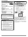
10.5. The RF Status indicator (blue LED)
The blue LED (light-emitting diode)
indicates the status of the RF mod-
ule. It is only exposed when the
transmitter is switched on.
LED flashes normally
Î RF transmission present
The LED flashes briefly at regular intervals, thereby in-
dicating that the transmitter is ready for use, and is
broadcasting an RF signal.
LED flashes at high rate
Î Transmitter is in binding mode Î 10.2.
The LED flashes briefly at regular intervals, thereby in-
dicating that the transmitter is ready for use, and is
broadcasting an RF signal.
LED glows constantly
Î Transmitter is working with reduced output
for range checking Î 3.2.
The LED glows constantly, thereby indicating that the
transmitter is broadcasting an RF signal with reduced
output power.
! Note: do not fly with reduced output !
The constantly glowing LED, a regular audible alarm
trill and the message “LO POW” (alternating with the
model name and / or the current menu) on the screen
are intended to alter you to the fact that you must not
fly a model with the transmitter set to low power.
Reduced power mode can only be switched off by
switching the transmitter itself off, then on again.
10.6. General notes
Discuss frequencies with other pilots!
(frequency monitoring)
The conventional method of monitoring frequen-
cies is not necessary with 2.4 GHz transmission
systems. Nevertheless you should always inform
the frequency monitor official or the flight director
at the site that you are operating a 2.4 GHz trans-
mitter.
Transmit in the approved frequency range only!
Before you operate the M-LINK system in certain
countries you will need to activate the - restricted -
frequency range approved for that region.
A summary of the countries affected in this way
can be found in the separate sheet entitled “Using
the 2.4 GHz M-LINK system in a restricted fre-
quency range”.
The approved frequency ranges vary, and are
country-specific. If necessary, activate the re-
stricted frequency range in the FRANCE menu.
12. Transmitter settings and in-
formation displays
12.1. Transmitter settings
Menu: (SETUP) TRANSMITTER
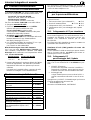
12.1.1. Complete transmitter reset
Menu: (SETUP, TRANSMITTER) RESET
In this menu the transmitter can be reset to the state in
which it was originally delivered. This means:
• Model memory 1 is set up with a model of the
EASY type.
• All data in model memories 2 to 18 is erased.
• The owner’s name is reset to “------”.
• The language for the menu texts is set to
“EN” (English).
How to access the RESET menu:
4 to MENU r (SETUP appears)
r (MODEL appears) 3 to TRANSMITTER
r (BAT AL appears) 3 to RESET
Open the menu with a brief press r on the 3-D digi-
adjuster (the “0” flashes). At this point you must enter
the number “18” using the 3-D digi-adjuster.
The RESET is only carried out if you switch the
transmitter off while the number “18” is flashing.
We have adopted this procedure in order to exclude to
the greatest possible extent the possibility of carrying
out a RESET accidentally.
The number 18 was arbitrarily chosen as code number,
and is easy to remember because the C
OCKPIT SX M-
LINK has eighteen model memories.

Supplement to the manual
MULTIPLEX Modellsport GmbH & Co.KG • Westliche Gewerbestraße 1 • D-75015 Bretten (Gölshausen) • www.multiplex-rc.de Seite 7/9
ENGLISH
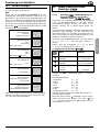
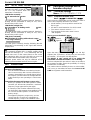
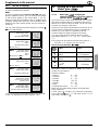
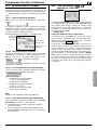
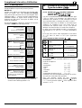
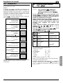
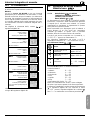
12.2. The INFO displays
The following table shows the seven INFO displays,
and the information they provide.
NEW:
If you are operating the C
OCKPIT SX M-LINK with a te-
lemetry-capable receiver, you can read off the voltage
of the receiver battery in the menu INFO 7. For ad-
ditional security the transmitter emits an audible alarm
if battery voltage falls below the (user-variable) alarm
threshold; for more details please see the receiver in-
structions.
You can “leaf through” the INFO displays by turning 3
4 the 3-D digi-adjuster.
INFO 1 Model type symbols
Model memory number
Model name
Transmitter battery voltage
INFO 2 Model type symbols
Model memory number
Timer 1
Transmitter battery voltage
ª resets Timer 1 *
INFO 3 Model type symbols
Model memory number
Timer 1
Timer 2
ª resets Timer 1 and
2 *
INFO 4 Model type symbols
Model memory number
Timer 2
ª resets Timer 2 *
INFO 5 Model type symbols
Model memory number
Transmitter operating time
INFO 6 Model type symbols
Model memory number
Owner’s name (if entered)
Software version
INFO 7 Model type symbols
Model memory number
Receiver battery voltage
(telemetry-capable receivers only)
* You can reset the various timers with a long press ª
on the 3-D digi-adjuster in INFO displays 2 to 4.
13. Setting up a new model
Model type: EASY
13.7.4 Model type EASY: changing the
standard assignment of receiver output 5
(aileron). Menu: (MIXER) A-->S5:
If you have set up a new model using the EASY model
type, then receiver output 5 is assigned to the second
aileron servo. If this is what you want, you do not need
to make any changes in this menu.
However, many model aircraft feature no ailerons at all,
or only require a single aileron servo to operate both
ailerons. For such cases it is possible to assign
receiver output 5 to other functions if necessary.
You can control receiver output 5 using any of the
transmitter controls A, E, R, THR, SP, F or the switch
PH.
This change can be carried out in the menu point A--
> S5 in the MIXER menu (see also 13.7.3).
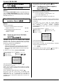
How to access the menu A-->S5:
Action Effect
1. 4
r
left to MENU
confirm
SETUP appears
2. 3
r
right to MIXER
confirm
THR>S4 appears
3. 3
r
right to
A-->S5
confirm
A-->S5 flashes
By turning the 3-D rotary control (43) you select the
transmitter control or switch to which you want to
assign receiver output 5 :
Receiver output 5:
= Aileron: A-->S5
= Elevator: E-->S5
= Rudder: R-->S5
= Throttle: THR>S5
= Spoiler: SP->S5
= Flap: F-->S5
= Flight phase switch: PH->S5
Note: you can select three positions using the flight
phase switch PH.
A brief press (r) confirms your selected assignment.
Turn to the left (4) to EXIT, and return to the MIXER
menu with a brief press (r).
2.1
2

COCKPIT SX M-LINK
MULTIPLEX Modellsport GmbH & Co.KG • Westliche Gewerbestraße 1 • D-75015 Bretten (Gölshausen) • www.multiplex-rc.de Seite 8/9
14. Setting up a new model
Model type: ACRO
14.6. Activating flight phases
14.10.1. What is possible with flight phases?
NEW:
The C
OCKPIT SX M-LINK allows you to set the value for
EXPO separately for each flight phase. The value is
set using the same method as for Dual-Rate
(Î 14.10.2.)
18. Managing model memories
Menu: MEMO
NEW:
Two additional menus:
• Transmitting Fail-Safe settings to the receiver
Menu: SENDFS Î 18.6.
• Activating / disabling Fast-Response
(14 ms pulse rate)
Menu: F-RESP Î 18.7.
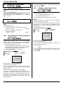
18.6. Transmitting the Fail-Safe positions
to the receiver
Menu: (MEMO) SENDFS
All M-LINK receivers feature Fail-Safe. If no valid signal
is picked up, the servos move to a user-programmable
position after a certain waiting time. The following
methods of determining these positions are available:
1. The SET button on the receiver
Use the transmitter to move all the servos to the de-
sired positions, then briefly press the SET button on
the receiver (Î see receiver instructions).
2. C
OCKPIT SX M-LINK SENDFS menu
How to access the SENDFS :
4 to MENU, r (SETUP appears),
3 to MEMO, r (GO TO appears),
3 to SENDFS,
Briefly press the 3-D digi-adjuster (r).
The 0 on the screen flashes.
Use the transmitter to move all the receiver outputs
(servos, speed controller) to the desired positions, and
hold them there.
Now turn the 3-D digi-adjuster to the right 3.
It makes no difference whether you turn it by one or
more clicks. The number in the bottom line now runs
through the range 0 to 7, indicating the transmission of
the seven Fail-Safe positions to the receiver. When the
transmission is complete, the 0 appears again, this
time not flashing.
You can now quit the menu by turning the 3-D rotary
control to the left 4 via EXIT, or with a long press ª
on the 3-D digi-adjuster.
18.7. Activating / disabling Fast Res-
ponse (fast frame rate)
Menu: (MEMO) F-RESP
The COCKPIT SX M-LINK can generate servo signals
with two different frame rates.
• 21 ms (default, Fast-Response = 0)
• 14 ms (Fast-Response = 1)
The servo signals are repeated every 14 / 21 ms.
NOTE:
The shorter frame rate (14 ms) may cause analogue
servos to run jerkily or oscillate.
At the 21 ms frame rate all servos should work without
problem; that is why this setting is programmed as the
default value. F-RESP can be set separately for each
model memory.
How to access the menu F-RESP:
4 to MENU, r (SETUP appears),
3 to MEMO, r (GO TO appears),
3 to F-RESP,
Press the 3-D digi-adjuster briefly (r).
The 0 in the display flashes.
You can now use the 3-D digi-adjuster to select your
preferred mode of operation:
0 = 21 ms
1 = 14 ms
You can quit the menu by turning the 3-D rotary control
to the left 4 via EXIT, or with a long press ª on the 3-
D digi-adjuster.

Supplement to the manual
MULTIPLEX Modellsport GmbH & Co.KG • Westliche Gewerbestraße 1 • D-75015 Bretten (Gölshausen) • www.multiplex-rc.de Seite 9/9
ENGLISH
20. Trainer mode operations
20.2. The COCKPIT SX as Pupil transmitter
If used as a Pupil transmitter, the COCKPIT SX M-LINK
can be connected to the following MULTIPLEX
Teacher transmitters:
C
OCKPIT SX, COCKPIT SX M-LINK
PROFI mc 4000, PROFI mc 3010 / 3030
ROYALevo / pro 7 / 9 / 12 / 16
(you will find a table on the Internet showing fur-
ther types)
If you wish to use the C
OCKPIT SX M-LINK as a Pupil
transmitter, follow this procedure:
1. Switch both transmitters
off.
2. Insert the plug marked Pupil into the multi-function
socket of the C
OCKPIT SX M-LINK transmitter. Insert
the plug marked Teacher into the multi-function
socket of the Teacher transmitter.
3. Switch on the Teacher transmitter only
!
Power is fed to the C
OCKPIT SX M-LINK via the
Trainer lead.
PUPIL flashes on the screen.
4. Use the 3-D digi-adjuster to select the pupil type
PUPILM for the following MULTIPLEX Teacher
transmitters:
e.g. PROFI mc 3010 / 3030 / 4000
Note: ROYALevo / pro as Teacher transmitter
If you use a ROYALevo / pro 7 / 9 / 12 / 16 as Teacher
transmitter, the selected Teacher type on the
ROYALevo / pro must be the same as the Pupil type
on the C
OCKPIT SX M-LINK:
ROYALevo / pro
COCKPIT SX M-LINK
TeacherM Î PUPILM
TeacherU Î PUPILU
5. A brief button press
(r) stores the setting
permanently. For safety’s sake it is now no longer
possible to change the transmitter setting.
If you wish to terminate Pupil mode, you must switch
the Teacher transmitter off, and disconnect the
Trainer lead.
21. Accessories and spare parts
Item Order No.
2.4 GHz transmitter aerial # 89 3007
Aluminium stick-tops # 7 5304
6-cell NiMH transm. battery, 1800 mAh # 15 6001
Transmitter case # 76 3323
Transmitter tray # 8 5306
PROFI transmitter neckstrap # 8 5646
Padded cushion for PROFI neckstrap # 8 5641
"Cross-over" transmitter support strap # 8 5640
USB simulator interface lead # 8 5153
PC interface for data back-up / update # 8 5148
Trainer lead (straight connectors)
Trainer lead (right-angled connectors)
Î 20.
# 8 5121
# 8 5118
For more information relating to accessories and re-
placement parts please consult the current main cata-
logue or our Internet website: www.multiplex-rc.de.
22. Multi-function socket interfaces
The multi-function socket of the COCKPIT SX M-LINK
provides the following functions:
• Charge / discharge the transmitter battery Î 8.
• Trainer mode operations Î 20. Î 20.2.
• PC socket for flight simulator Î 22.1.
• PC socket for data back-up / update Î 22.2.
22.1. PC socket for flight simulator
The COCKPIT SX M-LINK can be used directly and
without further modification as a control unit for many
flight simulators. Special interface leads for
MULTIPLEX transmitters are available from flight simu-
lator manufacturers.
If you have queries, please consult the manufacturer of
your simulator program.
Free model flight simulator (FMS) on the
MULTIPLEX website
The USB interface lead for use with this simulator is
available from model shops under Order No. # 8 5153.
22.2. PC socket for data back-up / update
If used with the free PC program “COCKPIT SX Data-
Manager” and the PC interface lead, # 8 5148, the
C
OCKPIT SX M-LINK offers the following facilities:
• UPDATE (Firmware)
When software corrections, modifications or ex-
pansions become available, you can download
them from the Internet and load them into your
transmitter.
• Data back-up
You can store data for individual models on your
PC, and load them back into your transmitter if
and when required.
The PC program “COCKPIT SX DataManager” is
available on our website as a free download. You will
find it under DOWNLOADS, SOFTWARE at our web-
site:
www.multiplex-rc.de
Page is loading ...
Page is loading ...
Page is loading ...
Page is loading ...
Page is loading ...
Page is loading ...
Page is loading ...
Page is loading ...
Page is loading ...
Page is loading ...
Page is loading ...
Page is loading ...
Page is loading ...
Page is loading ...
Page is loading ...
Page is loading ...
Page is loading ...
Page is loading ...
Page is loading ...
Page is loading ...
Page is loading ...
Page is loading ...
Page is loading ...
Page is loading ...
Page is loading ...
Page is loading ...
Page is loading ...
Page is loading ...
Page is loading ...
Page is loading ...
Page is loading ...
-
 1
1
-
 2
2
-
 3
3
-
 4
4
-
 5
5
-
 6
6
-
 7
7
-
 8
8
-
 9
9
-
 10
10
-
 11
11
-
 12
12
-
 13
13
-
 14
14
-
 15
15
-
 16
16
-
 17
17
-
 18
18
-
 19
19
-
 20
20
-
 21
21
-
 22
22
-
 23
23
-
 24
24
-
 25
25
-
 26
26
-
 27
27
-
 28
28
-
 29
29
-
 30
30
-
 31
31
-
 32
32
-
 33
33
-
 34
34
-
 35
35
-
 36
36
-
 37
37
-
 38
38
-
 39
39
-
 40
40
-
 41
41
-
 42
42
-
 43
43
-
 44
44
-
 45
45
-
 46
46
-
 47
47
-
 48
48
-
 49
49
-
 50
50
-
 51
51
-
 52
52


Multiplex Technology COCKPIT SX M-LINK Operating instructions
- Category
- Remote controlled toys
- Type
- Operating instructions
- This manual is also suitable for
Ask a question and I''ll find the answer in the document
Finding information in a document is now easier with AI
in other languages
Related papers

Other documents
-
Allegro Industries Lehrer Schueler Stick Owner's manual
-
MULTIPLEX RX-6 Owner's manual
-
-
-
-
-
MULTIPLEX Profi Tx 9 Owner's manual
-
-
-
MULTIPLEX RX-6-DR light Owner's manual