Champion ESSICK N46W User manual
- Category
- Barbecues & grills
- Type
- User manual

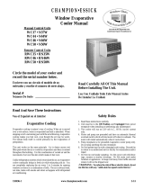
Circle the model of your cooler and
record the serial number below.
Read Carefully All Of This Manual
Before Installing The Unit.
Encierre con un circulo el modelo de su
enfriador y escribe el número de serie abajo.
Lea Con Cuidado Todo Este Manual Antes
De Instalar La Unidad.
Serial #
Número De Serie
Read And Save These Instructions
Evaporative Cooling
Evaporative cooling is nature’s way of cooling. When air is moved
over a wet surface, water is evaporated and heat is absorbed. When
stepping out of a swimming pool with the wind blowing, evaporative
cooling makes you feel cool, even though the air may be warm.
The human body itself is cooled primarily by the evaporation of
perspiration.
This unit works on the same principle. Air is drawn across wet
fi lter pads where the air is cooled by evaporation and then circulated
throughout the building. It is this combination of cooled air and the
movement of air over the skin which makes it feel cool.
Unlike refrigeration systems which recirculate the air, an evaporative
cooler continually brings in fresh air while exhausting old air. You
are completely replacing the air every 2 to 4 minutes by opening
windows or doors or a combination of both. The air is always fresh,
not stale, laden with smoke and odors as happens with refrigerated
air conditioning.
Vea el Español en el interior
110496-1 9-09www.championcooler.com
Manual Control Units
WC37 • N37W
WC44 • N44W
WC46 • N46W
WC50 • N50W
Remote Control Units
RWC35 • RN35W
RWC46 • RN46W
RWC50 • RN50W
Safety Rules
1. Read these instructions carefully.
2. Unit must be in the Off Position and Unplugged from power
receptacle when installing or performing any maintenance.
3. This cooler will run on 120 volt A.C., 60 Hz (cycle) current
only.
4. Motor and pump are grounded and have an automatic thermal
overload switch which will shut motor off when it overheats. The
motor will restart automatically when it cools down.
5. Pump receptacle is for grounded evaporative cooler pump only.
Do not plug anything else into receptacle.
WARNING: To reduce the risk of fi re or electric shock, do not
use this fan with any “solid-state fan speed control device.”
Convertible Kit Not Shipped With Cooler
Available Upon Request At No Additional Cost
W
i
n
d
o
w
U
n
i
t
s
W
i
t
h
C
o
n
v
e
r
t
i
b
l
e
G
r
i
l
l
e
CHAMPION•ESSICK
Window Evaporative
Cooler Manual

2
110496-1
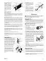
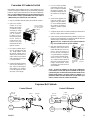
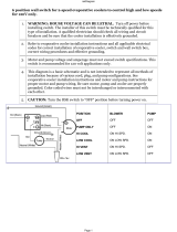
Cooler Installation
Installing House Legs
• NOTE: If installing unit without the use of the installation kit,
omit these directions and those pertaining to Fig. 2.
• Remove two corner screws in the bottom pan (A-Fig 1).
• Place the house leg bracket in the
corner of the bottom pan, using the
two top holes in the bracket (B-Fig 1).
Replace the two previously removed
screws to hold the house leg bracket
in place (As shown by dotted house
leg bracket).
• Refer to the instructions “Adjust
house legs” below for adjusting the
house legs.
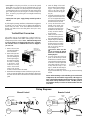
Mounting Cooler
CAUTION: Make sure that the mounting surface is strong
enough to support the operating weight of the cooler when in use.
(For operating weight, see Specifi cation Table.)
CAUTION: Never plug in cooler until installation is complete
and unit has been tested for rigidity.
• Lift out all removable louvered sides.
• Screw chain hooks into window facing. Position the two chain
hooks above the neck of
the cooler a distance equal
to the width of the cooler
apart (A-Fig. 2). Hook
one hanger chain in each
hook and then one “S”
hook in the other end of
each chain.
NOTE: The chain hooks
supplied with this mount-
ing kit are for use in wood.
Additional anchors can be
purchased at your local
hardware store for an-
choring in other types of
materials such as concrete
or brick.
Operation
Manual Control Units
• Pump setting. The rotary switch has 6 settings. The “Pump”
setting will operate the pump without the blower. For best results
turn the switch to “Pump” for a few minutes to wet the pads before
operating the fan.
• High and low cool settings. The “High Cool” and “Low Cool” set-
tings operate both the pump and the blower. Turn the unit to “Low
Cool” when possible. This lower speed allows the air to stay longer
in the wet pads and therefore increases it’s cooling effi ciency.
• High and low vent settings. The “High Vent” and “Low Vent”
settings operate the blower without the pump. This is useful on
cool nights or at times when just a fan is desired.
Remote Control Units
These units may be controlled using the 3 buttons on the front panel
of the cooler or with the remote control.
• PUMP button. Pressing this button toggles the pump on and off.
When the LED is lit, the pump is running. For best results turn
on the pump for a few minutes to wet the pads before operating
the fan. The pump must be on while operating the fan for cooling.
You may also want the pump turned off at times when just a fan is
desired.
• FAN button. Pressing this button will cycle the fan through High
Speed / Low Speed / Off. The LED’s on the front of the control
indicate wether the fan is on high speed, low speed or off (no LED’s
lit). Note: There will be a 2 second delay between a button press
and the operation of the fan.
• ON/OFF button. Pressing this button while the pump or fan is on
will turn everything off. Pressing it again while in the off state will
return the fan and pump to their previous operating settings. When
fi rst plugging in the cooler or after power has been interrupted,
pressing the On/Off button will start the cooler in the default state
which is with the pump on and the fan on high.
• Remote Control. To operate the cooler with the remote you must
be within 20 feet and in sight of the cooler. Aim the remote at the
front panel. The buttons on the remote control have the same func-
tions as the buttons on the front panel of the cooler. The remote
uses two AAA alkaline batteries which are included. A holder for
mounting on a wall is also included with the unit.
IF It falls down.
THEN CLOSE all of the windows one inch and try step 4 again.
IF It plasters itself to the screen.
THEN OPEN all of the windows one inch and try step 4 again.
IF It stays on the screen lightly.
THEN PERFECT. You are done. Enjoy your cooler.
Notes:
• When switching to Low Cool, you must rebalance your home.
Repeat step 4.
• Once you balance your home you can cool some areas more than
others by opening those windows more and closing the others by
the same amount. Repeat step 4 to make sure your home is still air
balanced.
Open Windows To Exhaust Air
An often misunderstood concept of evaporative cooling is the amount
of air that should be exhausted. How much should you open your
windows? The fact is that most people do not open their windows
enough. The following method will help you determine the amount
to open your windows.
Champion Air Balancing Method
1. Take a piece of tissue paper and cut it lengthwise into 3 equal
strips.
2. Turn your cooler on High Cool.
3. Open one window at least six inches wide in each room that you
want to cool.
4. Take the piece of tissue paper and put it up against the screen of
the open window furthest from the cooler discharge opening. Let
go of it. It will do one of three things.
Fig. 1
B
A
A
B
C
D
E
F
G
H
Window
Neck
“S” Hook
Fig. 2

3
110496-1
• Install window panel
retainers. Place two
panel retainer strips onto
bottom of neck flange
and position to the width
of the window. Cut the
strips to fi t if necessary.
These strips hold the
window fill-in panels
(Fig. 3).
• Position cooler in win-
dow. Position neck of
cooler so that bottom of neck fl ange rests on window sill and fl ange
(E-Fig. 2) is snug against edge of sill (H-Fig. 2). With cooler in
position, hook the “S” hooks into the holes of the top pan near the
back of the cooler (B-Fig. 2).
• Break fi ll-in panels to fi t. With cooler installed, as described
above, measure for each window fi ll-in panel and score with sharp
knife and straight edge guide to desired width. To break window
fi ll-in panels, the panel should be laid over the edge of a straight fl at
surface at the point to be broken off. Apply pressure on the edge
of the panel that extends over the edge of the surface and break off
unwanted piece.
• Install fi ll-in panels. Place one window fi ll-in panel on each side
of grill and into panel retainer strip at bottom of grill. Place the
other panel retainer strips onto top of neck fl ange and fi ll-in panels.
Be sure the panels are snug up against cooler neck.
• Place window behind retainer strip. Raise back of cooler so that
the window (D-Fig. 2) may be brought down behind top of panel
retainer strip (C-Fig. 2).
• Level Cooler. Adjust the chains to level the cooler.
• Adjust house legs. Pull out house legs so that the rubber bumpers
rest against house siding (F-Fig. 2). Tighten screw in retaining
collar. (G-Fig. 2).
Connecting Water
• Install overfl ow assembly. Remove
nut and place nipple through the hole in
the pan, with the rubber washer between
the pan and the head of the drain nipple
(Fig. 4). Screw on nut and draw up tight
against bottom of pan. Insert overfl ow
pipe in nipple to retain water. Overfl ow
pipe may be removed to drain pan when
necessary. A garden hose may be
screwed on the drain nipple to
drain water away from your unit.
• Connect water supply line. In-
stall a sillcock and water valve on
faucet as shown by fi gure 5. Place
the nut and ferrule on the tubing
and tighten the nut until water
tight.
Maintenance
WARNING: Before doing any maintenance be sure power is
off and unit is unplugged. This is for your safety.
Spring Start-Up
• Oil bearings. The blower bearings and cooler motor in this unit
should be oiled with a few drops of non-detergent 20/30 weight oil
once each year. The motor does not need oil if it has no oil lines
for oiling. Motors that have no oil lines are lifetime oiled at the
factory and require no further oiling for the life of the unit.
CAUTION: Do not over oil.
Over oiling can cause motor burn
out, due to excessive oil getting into
motor winding.
• Check belt tension. A 3 lb. force
should defl ect the belt 3/4 inches (see
Fig. 7). Readjust belt if needed.
• Clean pump. Cleaning the pump is necessary once a year at start-
up. For your safety, turn unit off and unplug from power receptacle.
Remove the pump from the mount slot. Remove the base of the
pump as shown in Fig. 8. Clean the pump and turn the impeller
to ensure free operation. Remove the pump spout and check for
any blockage. After cleaning,
reinstall the base onto the pump.
Press fi rmly to make sure it is
secure. Reattach the pump to
the mount in the cooler using
the plastic retainer to ensure that
the pump will not overturn. Do
not forget to replace the spout
and water delivery tube onto the
pump outlet.
• Replace Pads. Aspen pads should be replaced once or twice a
season, depending upon the length of the season. At the beginning
and at mid season a clean pad is more absorbent and effi cient and
will deliver substantially more cool air.
Winter Shut Down
• Drain water. Always drain all of the water out of the cooler and
water supply line when not in use for prolonged periods, and par-
ticularly at the end of the season. Keep the water line disconnected
from both the unit and water supply so that it does not freeze.
• Cover unit. To protect the life of the fi nish, a cover for the unit is
suggested in extended periods of non use.
• Install fl oat valve. Install
valve in the provided hole in
corner post (Fig. 6) and attach
water supply line.
• Fill pan. Allow water to fi ll
to within 1” of the top of the
overfl ow pipe and adjust fl oat
to maintain this water level.
This can be accomplished by
bending the float rod (Fig.
6).
Impeller
Remove
Base
Fig. 8
Fig. 3
Window Fill-In
Panels
Top Panel
Retainer
Bottom Panel
Retainer
Rubber Washer
Overfl ow Pipe
Nipple
Bottom Pan
Nut
Fig. 4
Faucet
Water Supply
Valve
Sillcock
Ferrule
Nut
Fig. 5
Float Rod
Water Supply
Line
Washer
Nut
Ferrule
Nut
Fig. 6
Corner Post
Fig. 7
3 Lb.
3/4 Inches

4
110496-1
• Cover grill. To help keep out cold air you can use the optional
plastic grill cover. This cover may be purchased from your local
distributor. To install the cover, line up the grill cover with the grill
so that the tabs on the cover will slide over the center section of the
grill. Slide the grill cover onto the grill. The tabs will snap into
place. To remove, just pull the grill cover straight forward away
from the grill.
• Unplug unit from power supply during extended periods of
non-use.
By following the operating, installation, and maintenance suggestions
as outlined, you can get many years of effi cient and satisfactory
service from your cooler. In the event additional information is
desired, your dealer will be more than glad to assist you in every
possible way.
Vertical Duct Conversion
This window unit can be reconfi gured to a vertical tunnel con-
fi guration for installation into smaller width openings. Follow the
subsequent steps if this is desired. Note: Tunnel mount strips used
to convert tunnel are not shipped with this cooler. If desired,
call Customer Service at 1-800-643-8341 to have it shipped to
you at no cost.
1. Remove the 9 screws
from the sides and bot-
tom of the tunnel.
2. Remove the top 4 mid-
dle screws of the top
pan while holding the
tunnel in place (Fig 9).
Be careful not to drop
the tunnel, or damage
to the electric cords
could occur. You may
need to loosen other
screws in the top pan
to make it easier to remove the tunnel.
3. Rotate the tunnel 90 degrees counter-clockwise (Fig 10). Be care-
ful as you rotate the tunnel that you don’t damage or disconnect
the cords which are still connected to the controls and the front
panel.
4. Insert the fl ange of the tunnel
between the front panel and the
top pan. Line up the two larger
holes in the tunnel with the
center two holes of the top pan.
(Fig 11).
5. Using the screws taken from the
top pan, secure the tunnel to the
unit. Do not tighten the screws,
leave them loose until the rest of
the tunnel has been secured.
6. Line up the three holes at the
bottom of the tunnel with
the holes in the front panel.
Using the screws taken from
the bottom of the tunnel pre-
viously, secure the tunnel to
the front panel.
7. Make sure all the screws re-
moved from the top pan are in
place and tighten all screws.
8. Skip this step for the RWC35
& RN35W models. Remove
the three screws (2 in models
WC37 & N37W) from each
side of the front panel as
shown in fi gure 12.
CAUTION: Make sure that
you do not remove the bottom
most screw. It holds the blower
housing in place.
9. To cover up the gap in the front
panel, use the two strips of metal
obtained from Customer Service.
Line up the holes in the metal strips
to the holes in the front panel and
secure them with the screws pre-
viously removed in step 8. (See
Fig. 12) Install the metal strips so
that there is no gap between the
top pan and the metal strip. If there is a gap, turn the metal strip
around.
NOTE: When mounting a cooler with this type of vertical tunnel
confi guration, the unit should be supported by a fl at support or
stand. The installation method mentioned in the owner’s manual
using chains and legs should not be used. The fi ller panels in
the installation kit may be used to seal off the window above the
cooler duct.
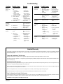
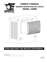
Wiring Diagrams
Manual Control Remote Control
Hi
Low
Gnd
Com.
Black
Red
Green
White
Plug Switch
Blower Motor
Pump
Motor
Hi
Low
Gnd
Com.
Black
Red
Green
White
Ground
Wire
Blower Motor
Pump
Motor
LockPlate
w/ Grommet
Control
Ground
Screw
Fig. 9
Remove top
screws last. Do
Not Drop Tunnel
Fig. 10
Fig. 11
Line up to the two
middle holes
Fig. 12
Do Not Remove
Bottom Screw
Metal
Strip

5
110496-1
Limited Warranty
This warranty is extended to the original purchaser of an evaporative cooler installed and used under normal conditions. It does not cover damages incurred
through accident, neglect, or abuse by the owner. We do not authorize any person or representative to assume for us any other or different liability in con-
nection with this product.
Terms And Conditions Of The Warranty
For Eight Years from date of purchase, we will replace the original base assembly if water leakage should occur due to rust out.
For One Year from date of purchase, we will replace any original component provided by Champion Cooler which fails due to any defect in material or fac-
tory workmanship only.
Exclusions From The Warranty
We are not responsible for replacement of cooler pads. These are disposable components and should be replaced periodically. We are not responsible for any
incidental or consequential damage resulting from any malfunction.
We are not responsible for any damage received from the use of water softeners, chemicals, descale material, plastic wrap, or if a motor of a higher horsepower
than what is shown on the serial plate is used in the unit.
We are not responsible for the cost of service calls to diagnose cause of trouble, or labor charge to repair and/or replace parts.
For limited warranty to be valid the evaporative cooler must be maintained per the Maintenance Section of this manual.
How To Obtain Service Under This Warranty
Contact the Dealer where you purchased the evaporative cooler. If for any reason you are not satisfi ed with the response from the dealer, contact the Customer
Service Department: 5800 Murray Street, Little Rock, Arkansas 72209. 1-800-643-8341. Email: info@championcooler.com.
This limited warranty applies to the original purchaser only.
Problem Possible Cause Remedy
Failure to
start or no air
delivery
Inadequate
air delivery
with cooler
running
Inadequate
cooling
1. No electrical power to
unit
• Fuse blown
• Circuit breaker
tripped
• Electric cord un-
plugged or damaged
2. Belt too loose or tight
3. Motor overheated
• Belt too tight
• Blower bearings dry
4. Motor locked
1. Insuffi cient air exhaust
2. Belt too loose
3. Pads plugged
1. Inadequate exhaust in
house
2. Pads not wet
• Pads plugged
• Open spots in pads
• Trough holes
clogged
• Pump not working
properly
1. Check power
• Replace fuse
• Reset breaker
• Plug in cords or
replace if damaged
2. Adjust belt tension
3. Determine cause of
overheating
• Adjust belt tension
• Oil blower bearings
4. Replace motor
1. Open windows or
doors to increase air
fl ow
2. Adjust belt tension or
replace if needed
3. Replace pads
1. Open windows or
doors to increase air
fl ow
2. Check water distribu-
tion system
• Replace pads
• Repack pads
• Clean trough and
unplug holes
• Replace or clean
pump (Unplug
unit)
Troubleshooting
Motor cycles
on and off
Noisy
Excessive
humidity in
house
Musty or
unpleasant
odor
Water drain-
ing from
cooler
1. Low voltage
2. Excessive belt tension
3. Blower shaft tight or
locked
4. Bearings dry
1. Bearings dry
2. Wheel rubbing blower
housing
3. Loose parts
1. Inadequate exhaust
1. Stale or stagnate water
in cooler
2. Pads mildewed or
clogged
3. Pads not wetting
properly
• Trough holes
clogged
• Pump not working
properly
1. Float arm not adjusted
properly
2. Overfl ow assembly
leaking
1. Check voltage
2. Adjust belt tension
3. Oil or replace bear-
ings (Unplug unit)
4. Oil bearings
1. Oil bearings
2. Inspect and realign
(Unplug unit)
3. Tighten loose parts
1. Open doors or win-
dows
1. Drain pan and clean
pads
2. Replace pads
3. Check water distribu-
tion system
• Clean
• Replace or clean
pump (Unplug
unit)
1. Adjust fl oat
2. Tighten nut and
overfl ow pipe.
Problem Possible Cause Remedy

6
110496-1
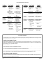
Model No.
Modelo
Motor Part #
Motor - Nº
HP
CV
Speed
Velocidad
Volts
Voltios
Motor Pulley Part #
Polea Del Motor - Nº
Drive Belt Part #
Banda - Nº
RWC35, RN35W 110442 1/3 2 115 110271 110226 (4L-480)
WC37, N37W 110445 1/3 2 115 110271 110211 (4L-450)
WC44, N44W 110445 1/3 2 115 110272 110215 (4L-560)
WC46, N46W
RWC46, RN46W
110445 1/3 2 115 110272 110215 (4L-560)
WC50, N50W
RWC50, RN50W
110447 1/2 2 115 110273 110215 (4L-560)
Model No.
Modelo
Weight (lbs.)
Peso (libras)
Cabinet Dimensions (in.)
Dimensions De La Caja (pulgadas)
Window Opening Req’d (in.)
Abertura Requerida (pulgadas)
Dry
Seco
Operating
Lleno
Height
Altura
Width
Anchura
Depth
Profundidad
Width
Anchura
Height
Altura
RWC35, RN35W 113 190 30 1/2 31 1/2 21 21 3/4 14 3/4
WC37, N37W 125 202 33 7/16 28 1/8 28 1/8 21 3/4 14 3/4
WC44, N44W 137 214 34 1/2 34 1/8 28 1/2 21 3/4 14 3/4
WC46, N46W
RWC46, RN46W
152 246 34 1/2 34 1/8 34 1/8 21 3/4 14 3/4
WC50, N50W,
RWC50, RN50W
155 249 34 1/2 34 1/8 34 1/8 21 3/4 14 3/4
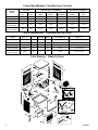
Parts Drawing / Dibujo De Piezas
Motor Specifi cations / Especifi caciones Del Motor
General Specifi cations / Especifi caciones Generales

7
110496-1
WC46, N46W
RWC46, RN46W
No. RWC35, WC37, WC44, WC50, N50W
N° Description / Descripción RN35W N37W N44W RWC50, RN50W
1. Top Pan / Tapa ........................................................................................................................ 322175-001 222903-001 222905-001 220901-003
2. Bottom Pan / Base De La Caja ..............................................................................................222175-002 222904-003 222903-006 220902-002
3. Louvered Side Assembly / Montaje De Reja Lateral ............................................................324006-107 (2) 324006-303 (3) 324006-106 (2) 324007-205 (3)
4. Water Trough, Side / Canal De Agua, Lateral .......................................................................226004-001 (2) 226003-001 (3) 226003-001 (2) 226003-002 (3)
5. Aspen Pads, Side / Filtros De Paja, Lateral ..........................................................................110084 (2) 110091 (3) 110094 (2) 110098 (3)
6. Pad Retainer, Side / Soporte Para El Filtro, Lateral .............................................................3PW-16 (6) 3PW-3 (9) 3PW-3 (6) 3PW-5 (9)
7. Louvered Back Assembly / Montaje De Reja Posterior ........................................................324006-108 See/Ve a #3 324007-205 See/Vea #3
8. Water Trough, Back / Canal De Agua, Posterior ................................................................... 226004-002 226003-002
9. Aspen Pads, Back / Filtros De Paja, Posterior ...................................................................... 110083 110098
10. Pad Retainer, Back / Soporte Para El Filtro, Posterior .........................................................3PW-15 3PW-5 (3)
11. Corner Post, With Float Hole / Poste De Esquina, Con Agujero Para Flotador ...................224018-002 224003-022 224003-032 224003-032
12. Corner Post, For Pump Mount / Poste De Esquina, Para Montar La Bomba .......................224018-001 224003-046 224003-047 224003-047
13. Front Panel / Panel Delantero ................................................................................................224175-001 224106-007 224103-006 224105-004
14. Tunnel / Túnel (Cuello Del Enfriador) ...................................................................................322120-001 322120-001 322120-001 322120-001
15. Blower Housing / Caja De La Rueda .....................................................................................324175-002 324104-009 324103-007 324105-006
16. Blower Wheel / Rueda ...........................................................................................................110765 12BW 15BW 16BW
17. Shaft, Blower Wheel / Eje De La Rueda ................................................................................110179 110182 110182 110183
18. Bearings, Blower Wheel Shaft / Cojinetes Del Eje De La Rueda ..........................................110351-001 (2) 110351 (2) 110351 (2) 110351 (2)
19. Pulley, Blower Wheel / Polea De La Rueda ..........................................................................110270 110274 110275 110275
20. Drive Belt / Correa .................................................................................................................110226 110211 110215 110215
21. Motor / Motor .........................................................................................................................110442* 110445* 110445* *
22. Pulley, Motor / Polea Del Motor ............................................................................................110271 110271 110272 *
23. Motor Mount / Montura Del Motor .......................................................................................320175-001 314003-001 314003-025 314003-024
24. Motor Mount Clips / Seguros Para Montar Motor ................................................................314005-001 314005-001 314005-001 314005-001
25. Float Valve / Válvula Del Flotador ........................................................................................FL-C FL-C FL-C FL-C
26. Pump Mount / Montura De La Bomba ...................................................................................222175-005 218001-031 218001-031 218001-031
27. Pump Screen
/ Malla Para La Bomba ...................................................................................281001-001 281001-001 281001-001 281001-001
28. Pump / Bomba ........................................................................................................................110436 110436 110436 110436
29. Pump Retainer / Sujetador De La Bomba ..............................................................................110714 110714 110714 110714
31. Tube, Water Delivery / Tubo De Agua ...................................................................................310716 310716 310716 310716
33. Water Distributor Assembly / Sistema Del Distribuidor De Agua .........................................3D-15 3D-2 3D-3 3D-10
34. Holder, Water Distributor / Soporte Para El Distribuidor De Agua ...................................... 110574 (3) 110574 (3) 110574 (6)
35. Over Flow Assembly / Montaje De Desagüe .........................................................................3OA-1 3OA-1 3OA-1 3OA-1
36. House Leg Collar Assembly / Montaje De Collar De La Pata ..............................................3HL-3 (2) 3HL-1 (2) 3HL-1 (2) 3HL-1 (2)
37. House Leg / Pata ....................................................................................................................310811 (2) 310811 (2) 310811 (2) 310811 (2)
38. Retainers, Window Panels / Guarda De Retención Para Los Paneles ..................................110599 (4) 110599 (4) 110599 (4) 110599 (4)
39. Window Panels / Paneles De Relleno Para La Ventana ........................................................110603 (2) 110603 (2) 110603 (2) 110603 (2)
40. †Electrical Cord, Motor / Cable Eléctrico Del Motor ........................................................... 110364† 110364 110372†
41. †Wiring Harness / Cableado Eléctrico................................................................................... 110375† 110375 110375†
42. †Switch / Interruptor .............................................................................................................. 110425† 110425 110425†
43. †Knob, Switch / Perilla Del Interruptor ................................................................................ 110839-006† 110839-006 110839-006†
44. †Switch Box / Caja Para El Interruptor .................................................................................. 222006-001† 222006-001 222006-001†
45. †Lockplate, Manual Units / Placa De fi jación, Unidades De Control Manual ...................... 222007-001† 222007-001 222007-001†
46. †Grill Assembly, Maunual Units / Rejilla Completa, Control Manual .................................. 110839-1† 110839-1 110839-1†
46a. ‡Grill Assembly, Remote Units / Rejilla Completa, Control A Distancia .............................110839-2‡ 110839-2‡ - 110839-2‡
47.
‡Lockplate & Grommet, Remote Units / Placa De fi jación Con Pasahilo, Control A Distancia ..............322007-004‡ 322007-004‡ - 322007-004‡
48. ‡Electronic Control Assembly / Montaje De Control Electrónico .........................................110400‡ 110400‡ - 110400‡
49. ‡Dress Ring / Anillo Decorativo .............................................................................................110403‡ 110403‡ - 110403‡
50. ‡Remote Control / Mando A Distancia ...................................................................................110401-1‡ 110401-1‡ - 110401-1‡
51. **Grill Cover / Cubierta Para La Rejilla ..............................................................................110829** 110829** 110829** 110829**
52. **Bleed-Off Kit / Equipo De La Válvula De Desahogo ........................................................310586** 310586** 310586** 310586**
53. §Mount Strips For Vertical Tunnel / Tiras De Metal Para El Conducto Vertical ................70804§ 322008-001§ 322008-001§ 322008-001§
54. Blower Brace / Soporte Para La Caja De La Rueda .............................................................222175-003 (2)
* See motor specifi cation table. / Vea la tabla de especifi caciones del motor.
** Optional accessories. Must be purchased separately. / Accesorios opcionales. Debe comprarlos por separados.
† For Manual Control units. / Para las unidades de control manual .
‡ For Remote Control units. / Para las unidades de control a distancia.
§ Not included with unit. Call 1-800-643-8341 to obtain this part at no additional cost. / No incluido con la unidad. Llame 1-800-643-8341 para obtener esta parte
sin coste adicional.
NOTE: Standard hardware items may be purchased from your local hardware store.
NOTA: Artículos de uso corriente pueden comprarse en la ferretería de su localidad.
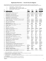
Replacement Parts List / Lista De Piezas De Repuesto
When ordering parts, please be sure to furnish the following information on all orders. Failure to do so may delay your order. /
Al pedir piezas, incluya toda la información siguiente con su pedido. El no proporcionar toda esta información resultará en una demora.
1. Cooler Model No. / Modelo de la unidad
2. Cooler serial number / Número de serie de la unidad
3. Description and part number / Descripción y número de pieza
4. Date of purchase / Fecha de compra
Page is loading ...
Page is loading ...
Page is loading ...
Page is loading ...
Page is loading ...
-
 1
1
-
 2
2
-
 3
3
-
 4
4
-
 5
5
-
 6
6
-
 7
7
-
 8
8
-
 9
9
-
 10
10
-
 11
11
-
 12
12


Champion ESSICK N46W User manual
- Category
- Barbecues & grills
- Type
- User manual
Ask a question and I''ll find the answer in the document
Finding information in a document is now easier with AI
in other languages
Related papers
-
Essick ESSICK RWC50 User manual
-
Champion RWC44 Owner's manual
-
-
-
-
-
-
-
-
Other documents
-
 Essick (R)N50W Owner's manual
-
 Essick Air N44W Operating instructions
-
 Essick Air N46W Operating instructions
-
Essick Air Products RN35W User manual
-
 Essick Air Products RWC35 User manual
-
 DIAL 3003 Operating instructions
-
 DIAL 71105 Operating instructions
-
Aspen Snow Cool IP 3 Operating instructions
-
MasterCool MMBT12 User manual
-
 Essick N30W User manual


