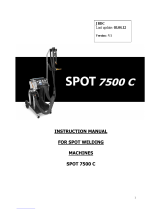
GYS GYSPOT 32 D.X Owner's manual

Category
Welding System
Type
Owner's manual

This manual is also suitable for

GYS GYSPOT 32 D.X COMPLETE is a versatile spot welding machine designed for various applications in car body workshops. It enables spot welding on sheet metals, welding of nails, rivets, discs, and pins, as well as smoothing of bumps and impacts. The device features both automatic and manual welding modes, allowing for precise control over welding parameters. With its pneumatic clamp and single-sided welding gun, it offers flexibility and ease of use. The GYSPOT 32 D.X COMPLETE ensures high-quality welds and is suitable for professional automotive repair and restoration work.

GYS GYSPOT 32 D.X COMPLETE is a versatile spot welding machine designed for various applications in car body workshops. It enables spot welding on sheet metals, welding of nails, rivets, discs, and pins, as well as smoothing of bumps and impacts. The device features both automatic and manual welding modes, allowing for precise control over welding parameters. With its pneumatic clamp and single-sided welding gun, it offers flexibility and ease of use. The GYSPOT 32 D.X COMPLETE ensures high-quality welds and is suitable for professional automotive repair and restoration work.

1
INSTRUCTION MANUAL
FOR SPOT WELDING
MACHINES
GYSPOT 32D.C
GYSPOT 32D.X
GYS
Last update: 18/10/17
Version : V5
2
Congratulations for the selection of this product which has been designed with great care ; Before installing and
using the product, please read carefully the following recommendations of safety in order to avoid accidents to
the users and damages of the welding process.
GYS can’t be responsible for the damages occurred to persons or things, which derive from the use of the
machine in following circumstances:
- Modification or neutralization of safety elements
- Non respect of the recommendations written in the manual instruction.
- Modification of the characteristics on the product
- Use of the accessories, which are different from the ones delivered by GYS.
I / PRESENTATION
This product has been designed to carry out the following operations in car body workshop:
- Spot welding machine on sheet metals with pneumatic pliers (except GYSPOT P230, P400),
- Welding of sheet metals with gun
- Welding of nails, rivets, discs and pins.
- Suppression of bumps and impacts ( impact of hail with the option “quick repair”).
II / SAFETY STANDARDS AND GENERAL PRECAUTIONS
GENERALITIES
1. Before disassembling the product’s body, plug out the lead cable.
2. The operators must have the appropriate qualification.
3. The operations of servicing can only be controlled by qualified technicians.
4. The operator is responsible for respect of the car manufacturers recommendations, concerning the protection
of electrical and electronic procedures ( car computer, car radio, alarm, air bag, etc…)
5. Before an operation of servicing, the power supply with compressed air must be cut off and off loaded.
6. The electrodes, arms, and the other secondary conductors can reach a very high temperature and remain hot
very long after having stopped the machine. Be careful: high risk of burns.
7. It is necessary to make a regular preventive maintenance.
ELECTRICITY
1. Check that the unity must be connected to the earth coupler and that the connection to the earth is in good
condition.
2. Check that the work bench is connected to the earth coupler.
3. Make sure that the operator has no contact with the metal parts to be welded without any protection or with
wet clothes.
4. Avoid to be in contact with the welding part.
5. Don’t make spot welding operations in very wet areas or on a wet floor.
6. Don’t weld with worn out cables. Check that there is no default with the isolation with stripped cables or with
loose connections.
7. Switch off the unit before replacing the electrodes..
8. Before controlling or repairing, please disconnect the unit directly to the level of the plug.
PROTECTION OF EYES AND BODY
1. During the welding process, the process must be protected from the eventual flashes of the electrical arc with
protection clothes like leather gloves, welding aprons, safety shoes, welding helmets or glasses for filtering
radiations and projections. As well during operations of rubbing and hammering, the operator must protect his
eyes.
2. The force of tightening of the clamp can reach 500 daN. Keep away all body parts from the mobile elements
to avoid risks of tightening.
3. Don’t keep rings, watches, or jewellery, which are current lead and can create burns.
4. All the protection board must be in good condition and maintained in place.
Protect the environment near the product against projections and reflections.
3
SMOKES AND GAZ
Welding operations can cause the emission of toxic smokes and harmful metallic dusts. The welding material
must be degreased and cleaned in order to limit the toxic gas during the welding process.
FIRE
1. Check that the sparks don’t cause fire especially near inflammable material.
2. Check that fire extinguishers are not too far from the operator.
3. Leave the product in a place with air movers.
4. Don’t weld neither on containers of combustibles and lubricants, even empty, nor on containers with
inflammable material..
5. Don’t weld in an atmosphere full with inflammable gas or fuel steam..
ELECTRO-MAGNETIC COMPATIBILITY
Near the spot welding, check :
- there is neither no other power supply cable nor control lines, nor phone cables, nor radio or TV
reception appliances, nor watches, nor mobile phones, nor magnetic cards, nor computers or any other
electronic appliance.
- there is in the surroundings (minimum 3 metres of each point of the product) no persons using active
medical appliances (pacemakers, acoustic prosthetics).
Make supplementary protections if other products are used in the same environment
III / CE certification
This product has been designed with respect of the European regulation .
Low voltage directive 2006/95/EC of 12.12.2006.
« EMC » directive (Electromagnetic Compatibility) 2004/108/EC of 15.12.2004.
Machinery directive 98/37/EC of 22.06.98.
and therefore are in compliance with the European harmonized standards:
EN 62135-1
EN 62135-2
EN 60204-1
4
IV / CONNECTIONS OF POWER SUPPLY CABLES
Electricity :
Two phases 400V 50Hz . Use of the PHASE 1, PHASE 2 and EARTH CONNECTION on a 3 phases plug.
Protection of the line
Circuit breaker 32A with D curve or delayed fuses 32A.
Case of dysfunction :
If the product releases the circuit breaker of the protection of installation, please check that you have the right
breaker size (32 A or more and D curve absolutely).
Compressed air :
Connect a compressed air pipe to the purifier behind the product. The service pressure can’t be over 8 bar. The
product can’t be used on an air network with a pressure less 3 bar.
5
V/ DESCRIPTION OF THE MACHINE
Front side :
Button of welding
current adjustment.
Indicator of
welding current
Indicator of time or steel
plate thickness.
Button of time or sheet
thickness adjustment.
Button of tool and
mode selection.
Clamp automatic mode.
Clamp manual mode.
Single side gun mode.
Carbon pen shrinking
Mode D :
- Smoothing of bumps.
- Procedure to swag
with a graphite pen.
Mode C :
- Welding of studs,
rivets, nails and bolts.
- Withdrawal of impact
of hail.
- Dent puller
Adjustment
of air
pressure.
Yellow indicator
of thermal
protection
Mode A :
Welding with the clamp in automatic mode.
The user shall enter the reference steel plate thickness.
Mode B :
Welding with the clamp
in manual mode.
The user shall select
the welding intensity
and the welding time.
Back side:
Circuit
breaker on/
off.
Air purifier
with
incoming
joint of
compressed
air.
Power
supply
cable
3 x 6 mm2
H07RNF.
6
VI / COOLING AND THERMAL PROTECTION
The cables are cooled with compressed air. The cooling process can be permanent if the red switch is on
Manual position or permanent except during the welding cycle if the red switch is on Automatic position. A
thermal protection forbid the use of the product in case of overheating (yellow indicator on the front side).
Recommendation :
When you use it intensively, you should cool the cables continuously with compressed air .
VII / WELDING WITH THE SINGLE SIDED WELDING GUN
- Connect the ground pad to the spade terminal of the generator.
- Fix firmly the ground pad near the place to be welded as possible.
In the case of a single sided spot welding process, leave always the ground pad on the metal sheet that is not
in contact with the welding electrode ( in order to make the current circulate in the two plates to be welded).
- select the mode to be used and adjust with the values written on the charts chapter IX.
Blinking of the displays :
the displays can blink because of 2 reasons:
- The thermal protection is activated because the station is too hot.
- The selected mode is incompatible with the tool already used.
This happens if the user presses the trigger of the single sided gun when the mode clamp is selected
on the control panel.
VIII / USE OF THE PNEUMATIC CLAMP
Select the function mode :
1 - Mode A: Welding with the clamp in automatic mode (thickness to be selected)
Proposed parameters for welding 2 pieces of galvanised steel with the clamp
Reference sheet thickness
Intensity
Time in périods
Pulsations
Forc in daN
C clamp
Forc in daN X
clamp arms length
120 mm
0.6 mm
HI
12
1
160
160
0.8 mm
HI
16
1
180
180
1.0 mm
HI
20
1
250
250
1.2 mm
HI
24
1
280
280
1.5 mm
HI
28
1
300
300
1.8 mm
HI
34
1
300
350
2.0 mm
HI
40
1
300
400
2.5 mm
HI
50
1
300
450
3.0 mm
HI
80
4
300
450
Table of reference sheet thickness:
2 - Mode B: Welding with the clamp in manual mode (intensity and duration of welding shall be selected)
Intensity and time adjustment table:
Intensity
high
Welding Time in periods
0……………..50
Intensity
99
Welding Time in periods
0……………..50
Intensity
98
Welding Time in periods
0……………..50
Intensity
---
Welding Time in periods
0……………..50
Intensity
41
Welding Time in periods
0……………..50
Intensity
40
Welding Time in periods
0……………..50
Clamp ajustment
AF
--
If “AF” clamp adjustment mode is selected, the clamp remains closed until the user presses the trigger
7
Blinking of the displays:
As for the welding gun mode, the display blinks when the machine is in thermal protection or if the selected
mode is unappropriate.
Cautions:
When using the clamp, the ground cable of the single sided gun must be disconnected from the car
body.
The electrodes must be regularly sharpened.
Blow off regularly the dehumidifying filter on the back side of the product. Please adjust with a medium
pressure of 6 bars.
IX : RECOMMENDED ADJUSTMENTS FOR BODY CAR WORKSHOP
(only indicative and to modulate depending on the type and the thickness of the sheets)
TOOL
OPERATION
MODE
POWER
TIMER
Gun
Single-side welding
C
HI
10 to 30
Gun
Tails welding
C
70
5 to 8
Gun
Nails and rivets welding
C
60
2 to 4
Gun
Star welding (sliding hammer)
C
50
1 to 5
Gun
Ring welding
C
60
2 to 4
Gun
Wavy wire (dent pulling)
C
60
2 to 4
Gun
Smoothing of bumps
D
20 to 40
Gun
Shrinking with carbon pen
D
20 to 40
Pneumatics
clamp
Welding 2 pieces of steel sheet : reference
steel thickness less than 2.5
1
pulsation
HI
10 to 50
Pneumatics
clamp
Welding 2 pieces of steel sheet : reference
steel thickness more than 2.5
4
pulsations
HI
52 to 96
X: C clamp arms :
Setting recommendations for welding mild steel sheets:
Sheets thickness in mm
Arm type
Minimum air
pressure (bars)
Suggested force
(daN)
From 0,4 to 1
C1-C2-C3-C4
3 to 4
100 to 200
1 to 2
C1-C2-C3
4 to 6
150 to 300
2 to 3
C1-C2-C3
6 to 8
250 to 350
Tilt electrode: 15°
Ref 052253
5,5 bar / 120 daN
8 bar / 300 daN
8 bar / 300 daN
8 bar / 300 daN
RC4
8
XII / X clamp arms :
Recommended clamping for welding galvanised steel with X clamp:
Sheet thickness in mm
Suggested Force in daN
Arm length inmm
Minimum air pressure in
bars
From 0,4 to 0,8
100 to 200
120
2 to 3
From 0,4 to 0,8
100 to 200
220
2 to 4
From 0,4 to 0,8
100 to 200
440
5 to 7
From 1 to 2
150 to 300
120
3 to 3,5
From 1 to 2
150 to 300
220
3 to 6
From 1 to 2
150 to 200
440
6 to 7
More than 2
300 to 500
120
4 to 7
More than 2
230 to 300
220
6 to 8
XIII / MAINTENANCE
Replacement of the X clamp arms:
- Adjust and tighten the arms of the clamp after having put the electrodes perfectly in line (torque: 15 Nm).
- Select the clamp adjustment function to check that the electrodes are in line.
This function is accessed in the manual clamp mode (B mode). « AF » has to be selected.
Replacement of the caps/electrodes:
To guarantee an efficient welding spot, it is necessary to replace the caps every 200 spots, using the dedicated caps
key.
Assemble the caps with copper grease (ref. 050440)
A type caps (ref. 049987)
F type caps (ref. 049970)
Bevelled caps (ref. 049994)
Several combinations are possible :
Set of X arms with a useful height of 120mm
Arms made of aluminium and electrodes made of copper
RX1: Useful length 120 mm
RX3: Useful length 220 mm, 20° tilt electrodes
RX4: Useful length 440 mm
RX2: longueur utile 220 mm, 30 + 85 mm
assymetrical electrodes
9
Cleaning or replacement of the welding tools
Any welding tool is degraded after a certain period of use. However all tools must stay clean in order to get the best
performance of the unit. When using the unit in pneumatic clamp mode, check the good state of the CAPS electrodes (flat,
rounded or bevelled). If this is not the case, clean them with sandpaper (fine grain) or replace them (see reference on the
unit).
All moving parts of machinery suffer constraints on their uses. Although monitoring is no screw loose, this could degrade the
quality of welds. If so, re-tighten.
For a use in gun mode, it is necessary to check the state of the tools: stars, single side electrode, carbide electrode and if
they look in bad condition clean or replace them.
The anti-dust filter at the back of the unit must regularly be cleaned to avoid the overheating of the generator.
Purging of the pneumatic filter
Regularly drain the dehumidifier filter placed on the rear side of the unit.
Generator maintenance
The maintenance and the repair of the current generator must be done by an appointed and GYS trained technician. Any
maintenance operation done by another person will cancel the warranty conditions. GYS cannot be held responsible for
damages or accidents which happen subsequently to operations performed by people exterior to GYS.
XIV / CHARACTERISCTICS
ELECTRICAL CHARACTERISTICS
Nominal input voltage : U1N
400V 3 ~ 50/60Hhz
Permanent input current : I1N
32
Power at 50% duty factor : S50
17 kVA
Permanent input power : Sp
12 kVA
Maximum welding input power : Smax
60 kVA
Secondary voltage :U2d
12 V.A.C
Maximum short-circuit output current : I2cc
7 800A
Maximum regulated welding current
7 500A
Circuit Breaker
32 Amp D curve
Duty cycle
0.5%
THERMAL CHARACTERISTICS
Ambiant temperature Range
+5°C +45°C
Transport and storage Temperature range
-25°C up to +70°C
Hygrometry
80 %
Altitude
2000m
Thermal protection by thermistor on the diode bridge
70 °C
MECHANICAL CHARACTERISTICS
Protection degree
IP21
Width
590 mm
Height
760 mm
Depth
1890 mm
Weight
98 kg
Welding clamp cable length
2 200 mm
Welding clamp cable cross-section
200 mm²
Single-sided welding gun cable length
2 600 mm
Single-sided welding gun cable cross-section
150 mm²
Earth cable length
2600 mm
Earth cable cross-section
150 mm²
PNEUMATICS CHARACTERISTICS
Minimum force : Fmin
100 daN
Maximum force F with C clamp : Fmax
300 daN
Maximum force F with C clamp with RC4 arm
120 daN
Maximum force F with X clamp and 440 mm arms
150 daN
Maximum force F with X clamp and 120 mm arms
500 daN
10
XV / TROLLEY ASSEMBLY
X30
X1
X26
X6
M8 x 12
M8
M8 x 85
M6
11
12
13
14
XVI / Electrical schematics
32D-X :
32D-C :
15
XVII Symbols
Caution! Read the user manual before use
Separate collection required Do not throw in a
domestic dustbin
Do not use in the open air.
Do not use the product under water projections.
IP21.
People wearing pace-makers should not
approach this product. Risk of interference and
disturbance of pace-makers near of the product.
Caution! Strong magnetic field.
People wearing active or passive implants must
be informed.
Use eye protection or wear safety glasses.
Body protection must be worn.
Hand protection must be worn. Risk of burns.
  • Page 1 1
  • Page 2 2
  • Page 3 3
  • Page 4 4
  • Page 5 5
  • Page 6 6
  • Page 7 7
  • Page 8 8
  • Page 9 9
  • Page 10 10
  • Page 11 11
  • Page 12 12
  • Page 13 13
  • Page 14 14
  • Page 15 15

GYS GYSPOT 32 D.X Owner's manual

Category
Welding System
Type
Owner's manual
This manual is also suitable for

GYS GYSPOT 32 D.X COMPLETE is a versatile spot welding machine designed for various applications in car body workshops. It enables spot welding on sheet metals, welding of nails, rivets, discs, and pins, as well as smoothing of bumps and impacts. The device features both automatic and manual welding modes, allowing for precise control over welding parameters. With its pneumatic clamp and single-sided welding gun, it offers flexibility and ease of use. The GYSPOT 32 D.X COMPLETE ensures high-quality welds and is suitable for professional automotive repair and restoration work.

Ask a question and I''ll find the answer in the document

Finding information in a document is now easier with AI