Bosch EVU-1082/95 User manual

Category
Loudspeakers
Type
User manual

This manual is also suitable for

EVU Series
User Manual
EVU-1062/95
EVU-1082/95
EVU-2062/95
EVU-2082/95
Table
of
Contents
INTRODUCTION ........................................................................................................ 7
Introduction ............................................................................................................................7
Electro-Voice Model Number Notation ................................................................................8
Optional Accessories .............................................................................................................9
Dimensions ............................................................................................................................9
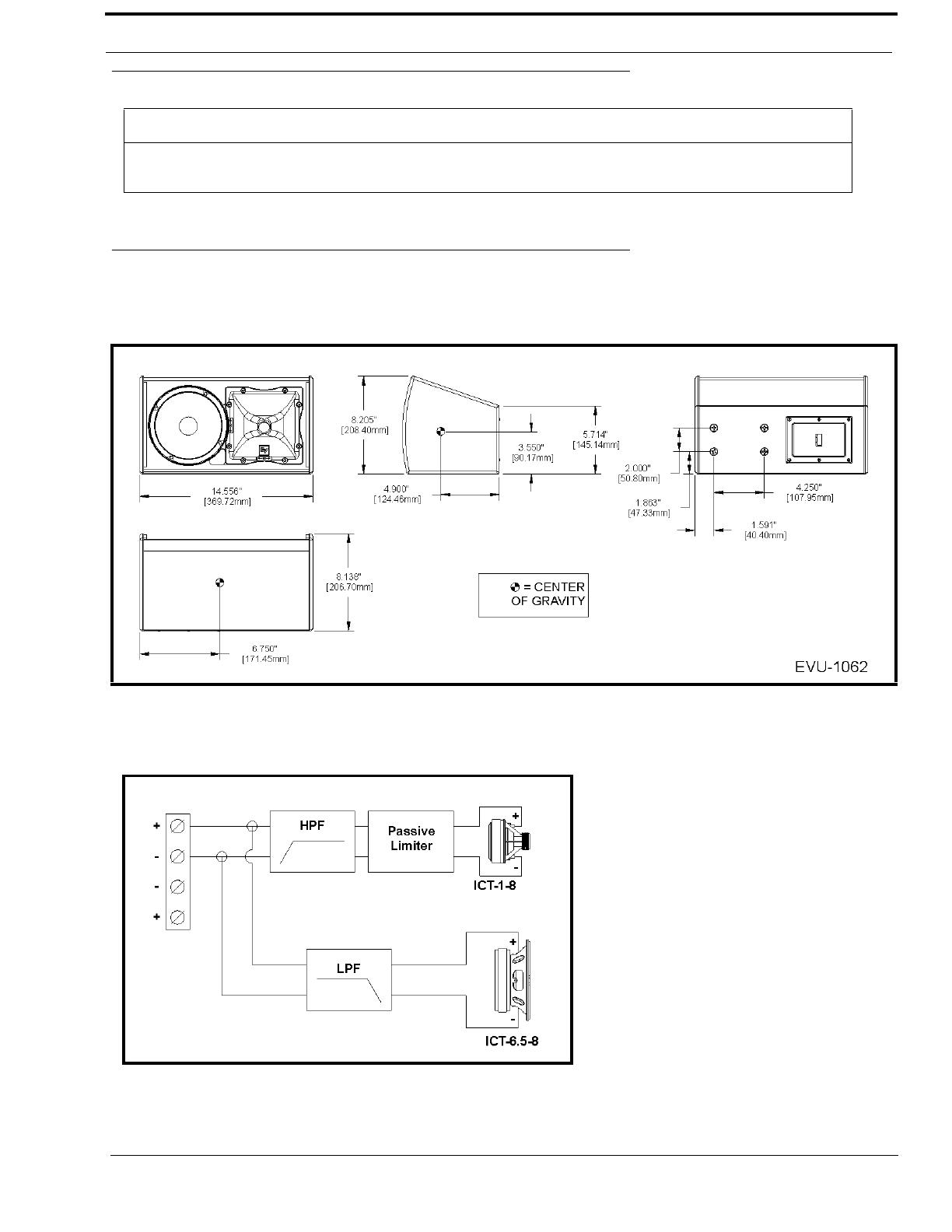
EVU-1062 Dimensions ....................................................................................................................9
EVU-1062 Block Diagram// .............................................................................................................9
EVU-1082 Dimensions ..................................................................................................................10
EVU-1082 Block Diagram .............................................................................................................10
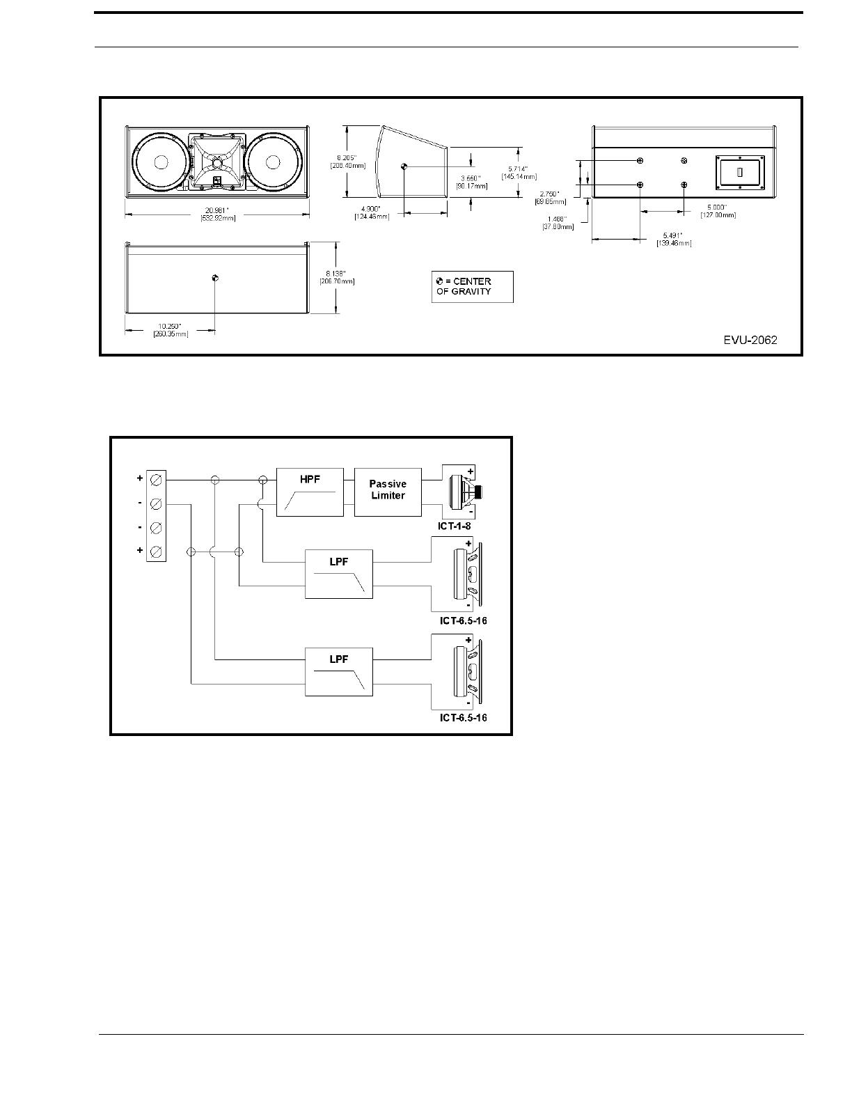
EVU-2062 Dimensions ..................................................................................................................11
EVU-2062 Block Diagram .............................................................................................................11
EVU-2082 Dimensions ..................................................................................................................12
EVU-2082 Block Diagram .............................................................................................................12
Parts List ..............................................................................................................................13
Tool List ...............................................................................................................................14
INSTALLATION ....................................................................................................... 15
Digital Signal Processing .....................................................................................................15
Preparing the EVU for Installation ......................................................................................16
Rotation of the High-Frequency Waveguide Sub Assembly .........................................................16
Connecting the Loudspeaker to the Signal Wires ................................................................17
Troubleshooting ...................................................................................................................17
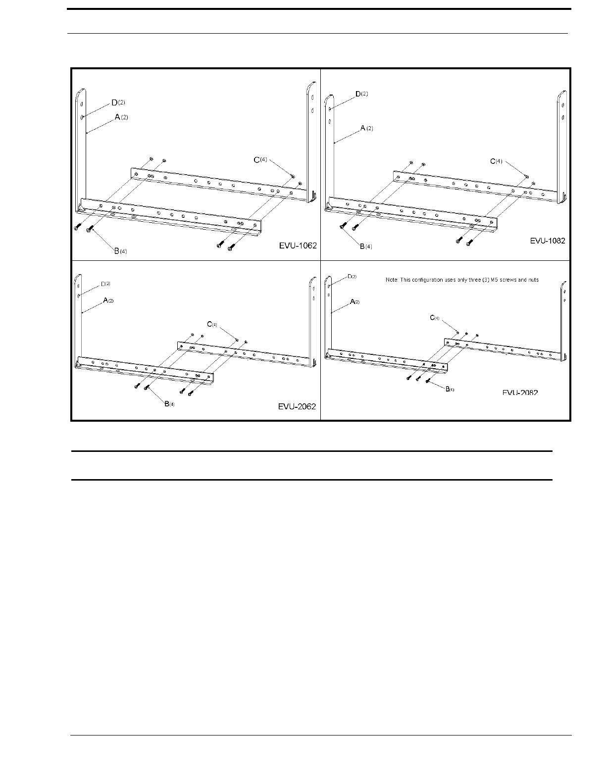
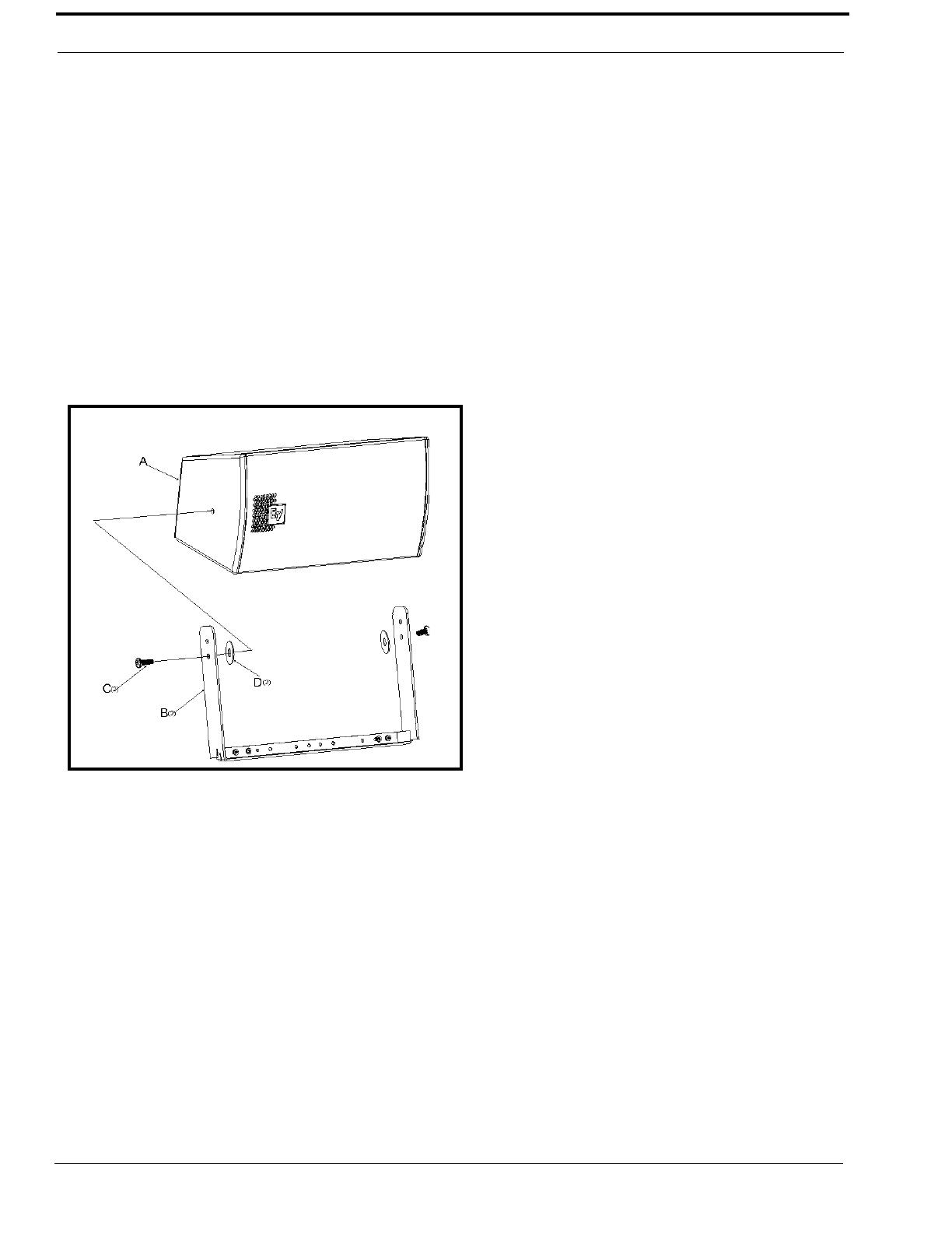
EVU Rigging .......................................................................................................................18
Universal U-Bracket .......................................................................................................................18
Mounting the Universal U-Bracket to the Wall ...................................................................21
Optional Omnimount Bracket ........................................................................................................22
Compatible Omnimount Models .................................................................................................22
Optional M8 Forged, Shoulder-Style Closed Eyebolt ...................................................................23
WORKING LOAD LIMITS AND SAFETY NOTICES ........................................... 25
Working Load Limit and Safety-Factor Definitions ............................................................25
Electro-Voice WLL ........................................................................................................................25
Factor of Safety ..............................................................................................................................25
System Working Load Limit Using EV Universal U-Bracket .......................................................26
Enclosure Working Load Limit Using Omnimount Bracket Attachment ......................................26
Enclosure Working Load Limit for M8 Forged, Shoulder-Style Closed Eyebolt Attachment ......26
Disclaimer ......................................................................................................................................26
List
of
Figures
FIGURE 1. Available EVU Systems .......................................................................................8
FIGURE 2. Dimensions and Center of Gravity for the EVU-1062 ........................................9
FIGURE 3. EVU-1062 Block Diagram ...................................................................................9
FIGURE 4. Dimensions and Center of Gravity for the EVU-1082 ......................................10
FIGURE 5. EVU-1082 Block Diagram .................................................................................10
FIGURE 6. Dimensions and Center of Gravity for the EVU-2062 ......................................11
FIGURE 7. EVU-2062 Bock Diagram ..................................................................................11
FIGURE 8. Dimensions and Center of Gravity for the EVU-2082 ......................................12
FIGURE 9. EVU-2082 Block Diagram .................................................................................12
FIGURE 10. EVU Series Part List ........................................................................................13
FIGURE 11. High-Frequency Waveguide Sub Assembly Orientation .................................16
FIGURE 12. Universal U-Bracket Assembly .......................................................................19
FIGURE 13. EVU-1062 Assembly—Example .....................................................................20
FIGURE 14. Universal U-Bracket Mounting Holes .............................................................21
FIGURE 15. Bolt Pattern for 30 Series Single Cabinet ........................................................22
FIGURE 16. Bolt Pattern for 60 Series Double Cabinet .......................................................22
FIGURE 17. Eyebolt Orientation ..........................................................................................24
7
CHAPTER 1
Introduction
Introduction
The Electro-Voice EVU series is a compact high power 2-way loudspeaker system used in a variety of applications where
high-quality sound reinforcement is required in an ultra compact light-weight enclosure. The enclosure design utilizes
asymmetrical angles to maintain tight clearances to wall and ceilings while providing optimal coverage patterns making it
ideal to blend into surroundings.
This design is optimized for wall, stage lip and under balcony applications. The EVU series incorporates the ICT (Install
Compact Transducer), a high-output 1.3in titanium compression driver coupled to a Constant Directivity*
1
90 x 50 rotatable
waveguide. The EVU woofers are developed using FEA (Finite Element Analysis) optimization to provide the highest
sensitivity while achieving the highest level of speech intelligibility.
The crossover designs uses 18dBper octave slopes with equalization for very smooth response in the vocal range, linear
off-axis response and a protection circuit for long term reliability. The EVU line is constructed of multi-ply hardwood
plywood enclosure with six (6) integral M8 suspension points to support a wide variety of mounting positions.
The EVU system is finished in textured paint available in either white or black. Each EVU system includes a universal
u-bracket to facilitate mounting. The u-bracket provides for a 330° unobstructed, translation of the loudspeaker. Additional
mounting points are located on the back of the enclosure for use with an Omnimount*
1
type bracket, available from
Omnimount Inc. An available 60W transformer kit is easily mounted over the input panel for use in distributed systems. An
NL-4 cover plate accessory is available to simplify use as a portable system. All of these features give you the flexibility to
address a large range of venues, quickly and precisely supporting customer requirements.
1. See “Copyright Notice” on page 27.
TABLE 1. Horn Pattern EVU Models
Model Number Horn Pattern
EVU-1062/95 90x50
EVU-1082/95 90x50
EVU-2062/95 90x50
EVU-2082/95 90x50
8
EVU Technical Manual
Electro-Voice Model Number Notation
The Electro-Voice Model Number notation indicates the loudspeaker series, woofer quantity, woofer diameter, quantity of
band passes in the system, and following a forward slash, the coverage pattern. An example using the EVU-1062/95 is shown
in Table 2. The EVU-1062/95 uses a single ICT series 6.5in. woofer in a two-way configuration and a 90° x 50° pattern.
Typical EVU systems are shown in Figure 18, with key dimensions, suspension points, weights and centers-of-gravity.
Engineering data sheets for each model, containing full specifications and dimensional drawings, are shipped with each
loudspeaker and can be downloaded from the Electro-Voice website, see “Contact Information” on page 27.
TABLE 2. Model Number Notation Description
Model
Number
EVU-1062/95
EVU - 1 06 2 / 95
Description
Loudspeaker
family/series
Number of
Woofers
Woofer Diameter
6.5in.
Number of Band
Passes (Two-Way)
Coverage
Pattern (90x50)
EVU-1062/95 EVU-1082/95
EVU-2062/95
EVU-2082/95
FIGURE 18. Available EVU Systems
9
Introduction
Optional Accessories
Dimensions
EVU-1062 Dimensions
EVU-1062 Block Diagram//
Item Description Part and Model Number
NL4 Cover Plate Kit Dual NL4 Input Panel Cover F01U216258 (EVU-CDNL4)
Transformer Kit 60 Watt Transformer Kit (70.7/100-V) F01U216257 (EVU-TK60)
FIGURE 19. Dimensions and Center of Gravity for the EVU-1062
FIGURE 20. EVU-1062 Block Diagram
10
EVU Technical Manual
EVU-1082 Dimensions
EVU-1082 Block Diagram
FIGURE 21. Dimensions and Center of Gravity for the EVU-1082
FIGURE 22. EVU-1082 Block Diagram
11
Introduction
EVU-2062 Dimensions
EVU-2062 Block Diagram
FIGURE 23. Dimensions and Center of Gravity for the EVU-2062
FIGURE 24. EVU-2062 Bock Diagram
12
EVU Technical Manual
EVU-2082 Dimensions
EVU-2082 Block Diagram
FIGURE 25. Dimensions and Center of Gravity for the EVU-2082
FIGURE 26. EVU-2082 Block Diagram
13
Introduction
Parts List
The EVU loudspeaker shipment includes the following:
Loudspeaker (A) 1 each
U-Bracket Sections (B) 2 each
M8 Pan Head Bolts (C) 4 each
M5 Pan Head Bolts (not shown) 4 each
M5 Nuts (not shown) 4 each
Rubber Washers (D) 2 each
EDS Sheet (not shown) 1 each
User Manual (not shown) 1 each
FIGURE 27. EVU Series Part List
14
EVU Technical Manual
Tool List
The tools required to prepare the EVU system for installation are as follows:
3/16in. flat blade screwdriver
Phillips #2 screwdriver
NOTE: This screwdriver is also required to install the optional transformer kit or NL4 cover plate. For more
information, see “Optional Accessories” on page 9.
15
CHAPTER 2
Installation
Digital Signal Processing
For full-range passive systems, the internal crossover/equalizer network sends low frequencies to the woofer and high
frequencies to the compression-driver/waveguide combination. In addition, the network tailors the frequency response and
levels of each individual driver so the overall frequency response of the loudspeaker is essentially flat over its design operating
range.
Once the ECU system
Once the EVU systems is installed in its venue, a DSP (Digital Signal Processor) is used to adjust the in-room frequency
response, based on the specifics of the venue. In addition, the DSP should be used to provide the high-pass filters
recommended to protect the EVU system against overdrive at frequencies below their operating range, failure to do so could
damage the low-frequency drivers if fed high-level signals below the system’s operating range. The recommended high-pass
filter frequencies for infrasonic protection of EVU system is shown in Table 3.
TABLE 3. Recommended High-Pass Filter Frequencies
Model Number Recommended High-Pass
Frequency (minimum)
EVU-1062/95 90Hz; 24dB Per Octave
EVU-1082/95 90Hz; 24dB Per Octave
EVU-2062/95 90Hz; 24dB Per Octave
EVU-2082/95 90Hz; 24dB Per Octave
16
EVU Technical Manual
Preparing the EVU for Installation
Rotation of the High-Frequency Waveguide Sub Assembly
All high-frequency waveguide sub assemblies have their horizontal and vertical patterns molded on the front of the waveguide
for easy identification of orientation. The high-frequency waveguide sub assembly can be rotated to change the high frequency
pattern.
NOTE: The high-frequency waveguide sub assembly is installed at the factory with the 90° wave pattern oriented along
the long axis of the enclosure for all models.
To change the high-frequency waveguide sub assembly’s orientation, do the following:
Tools: #2 Phillips screwdriver
1. Remove the eight (8) screws (A) from the top and bottom of the grille.
NOTE: The grilles on the single woofer models, EVU-1062 and EVU-1082, use six (6) screws.
2. Remove the grille (B).
3. Remove the eight (8) screws (C) holding the high-frequency waveguide sub assembly.
4. Rotate the high-frequency waveguide sub assembly 90° (D) until the desired pattern (90° or 50°) marking is located
along the long axis of the enclosure.
5. Reinstall the high-frequency waveguide sub assembly (D) with eight (8) screws (C).
6. Reattach the grille (B) to the front of the loudspeaker (E).
FIGURE 28. High-Frequency Waveguide Sub Assembly Orientation
17
Installation
Connecting the Loudspeaker to the Signal Wires
To connect the signal wires to the connector on the back of the loudspeaker, do the following:
NOTE: This procedure is not illustrated.
Tools: 3/16in.flat blade screwdriver
1. Loosen the + and - screws.
2. Attach the signal wires to the appropriate + and - terminal positions on the connector.
NOTE: Attach only one (1) signal wire per terminal.
3. Tighten the + and - screws until the signal wire is secure.
Troubleshooting
Problem Possible Cause Action
No Sound Amplifier Connect a known working test loudspeaker to the amplifier
outputs. If there is no sound, check that all the electronics are on,
the signal routing is correct, the source is active, the volume is
turned up, and so on. Correct/repair/replace as necessary. If there
is sound, the problem is in the wiring.
Wiring Verify you have connected the correct wire pairs to the amplifier.
Play audio at a low level through the amplifier (for example,
from a CD player or tuner). Connect the test loudspeaker in
parallel with the malfunctioning line. If the sound level has gone
or is very weak, the line has a short in it (possibly a severe scrape,
pinch, or staple puncture). If the sound level is normal, the wire is
open (possibly a cut wire or a missed connection). Observe
proper polarity and use the test loudspeaker to move down the
line and test each connection/junction until you find the problem
and correct it.
Intermittent output such
as crackling or distortion
Faulty Connection Check all connections at amplifier and speakers to ensure they
are all clean and tight. If the problem persists, it may be in the
amplifier or wiring. See Problem 1 above.
Constant noise such as
buzzing, hissing or,
humming
Defective amplifiers or
other electronic device
If the noise is present but no audio is playing, the likely cause is
the signal chain in the electronics. Evaluate each component as
necessary to isolate the problem.
Poor system grounding
or ground loop
Check and correct the system grounding, as required.
If these suggestions do not solve your problem, contact your nearest Electro-Voice dealer or Electro-Voice distributor.
See “Contact Information” on page 27.
18
EVU Technical Manual
EVU Rigging
All EVU loudspeaker systems incorporate heavy-duty M8 threaded accessory attachment points inside each enclosure. These
attachment points allow the user to install single systems in horizontal and vertical configurations. The universal U-Bracket
allows for installation in horizontal or vertical configurations with the ability to position the loudspeaker at any angle up to
330° of total rotation with the transformer kit accessory.
Accessory attachment points are used for the following:
Universal U-Bracket
M8 forged, shoulder-style closed eyebolts (not included)
Omnimount bracket (available from Omnimount)
Universal U-Bracket
The Universal U-Bracket and hardware, designed to work with all EVU models, is used to mount the loudspeaker and is
included with all EVU system shipments.
To assemble the U-bracket, do the following:
Tools: #2 Phillips screwdriver
1. Orient the two (2) bracket rails (A) for assembly.
2. Using the diagram appropriate to your installation, insert four (4) M5 pan head screws (B) through the first and
second bracket rails. See Figure 29.
NOTE: The EVU-2082 model’s bracket assembly uses three (3) M5 pan head screws.
3. Securely fasten the four (4) nuts (C).
NOTE: Bracket assembly for the EVU-2082 model uses three (3) nuts.
19
Installation
WARNING: The Universal U-Bracket is designed to hold the weight of one (1) loudspeaker. Never attempt to mount
multiple loudspeakers to a single u-bracket.
FIGURE 29. Universal U-Bracket Assembly
20
EVU Technical Manual
To install the assembled U-Bracket to the enclosure, do the following:
NOTE: All EVU systems are assembled in the following manner:
Tools: #2 Phillips screwdriver
1. Remove two (2) M8 flat head screws (C) from each end of the loudspeaker enclosure (A).
2. Position the loudspeaker enclosure inside the universal u-bracket (B).
3. Place one (1) M8 rubber washer (D) between the enclosure’s screw hole and the universal u-bracket on each side of
the enclosure.
NOTE: See Figure 29 for holes specific to the system being mounted.
4. Securely fasten one (1) M8 panhead screw through the bracket, washer, and enclosure on each side of the
assembly.
5. Position the loudspeaker at the desired angle.
6. Securely tighten the M8 flat head screw.
FIGURE 30. EVU-1062 Assembly—Example
  • Page 1 1
  • Page 2 2
  • Page 3 3
  • Page 4 4
  • Page 5 5
  • Page 6 6
  • Page 7 7
  • Page 8 8
  • Page 9 9
  • Page 10 10
  • Page 11 11
  • Page 12 12
  • Page 13 13
  • Page 14 14
  • Page 15 15
  • Page 16 16
  • Page 17 17
  • Page 18 18
  • Page 19 19
  • Page 20 20
  • Page 21 21
  • Page 22 22
  • Page 23 23
  • Page 24 24
  • Page 25 25
  • Page 26 26
  • Page 27 27

Bosch EVU-1082/95 User manual

Category
Loudspeakers
Type
User manual
This manual is also suitable for

Ask a question and I''ll find the answer in the document

Finding information in a document is now easier with AI