LSI Syncro CS 9286-8e User guide
- Category
- Interface cards/adapters
- Type
- User guide

Syncro™ CS 9286-8e Solution
User Guide
Version 1.0
March 2013
DB15-001017-00

LSI, the LSI & Design logo, Syncro, CacheVault, and MegaRAID are registered trademarks of LSI Corporation or its subsidiaries. All other brand and product names may be trademarks of their respective
companies.
LSI Corporation reserves the right to make changes to the product(s) or information disclosed herein at any time without notice. LSI Corporation does not assume any responsibility or liability arising out of
the application or use of any product or service described herein, except as expressly agreed to in writing by LSI Corporation; nor does the purchase, lease, or use of a product or service from LSI Corporation
convey a license under any patent rights, copyrights, trademark rights, or any other of the intellectual property rights of LSI Corporation or of third parties. LSI products are not intended for use in life-support
appliances, devices, or systems. Use of any LSI product in such applications without written consent of the appropriate LSI officer is prohibited.
This document contains proprietary information of LSI Corporation. The information contained herein is not to be used by or disclosed to third parties without the express written permission of LSI Corporation.
Corporate Headquarters Email Website
800-372-2447
Document Number: DB15-001017-00
Copyright © 2013 LSI Corporation
All Rights Reserved
Syncro CS 9286-8e Solution User Guide
March 2013
Revision History
Version and Date Description of Changes
Version 1.0, March 2013 Initial release of this document.

Table of Contents
Syncro CS 9286-8e Solution User Guide
March 2013
Table of Contents
LSI Corporation
- 3 -
Chapter 1: Introduction . . . . . . . . . . . . . . . . . . . . . . . . . . . . . . . . . . . . . . . . . . . . . . . . . . . . . . . . . . . . . . . . . . . . . . . . . . . . . . . . . . . . . . . . . . . . . . . . . . . . . . . . . 4
1.1 Concepts of High-Availability DAS . . . . . . . . . . . . . . . . . . . . . . . . . . . . . . . . . . . . . . . . . . . . . . . . . . . . . . . . . . . . . . . . . . . . . . . . . . . . . . . . . . . . . . . . . . . . . . . . . . . 4
1.2 HA-DAS Terminology . . . . . . . . . . . . . . . . . . . . . . . . . . . . . . . . . . . . . . . . . . . . . . . . . . . . . . . . . . . . . . . . . . . . . . . . . . . . . . . . . . . . . . . . . . . . . . . . . . . . . . . . . . . . . . . 5
1.3 Syncro CS 9286-8e Solution Features . . . . . . . . . . . . . . . . . . . . . . . . . . . . . . . . . . . . . . . . . . . . . . . . . . . . . . . . . . . . . . . . . . . . . . . . . . . . . . . . . . . . . . . . . . . . . . . . 5
1.4 Hardware Compatibility . . . . . . . . . . . . . . . . . . . . . . . . . . . . . . . . . . . . . . . . . . . . . . . . . . . . . . . . . . . . . . . . . . . . . . . . . . . . . . . . . . . . . . . . . . . . . . . . . . . . . . . . . . . . 6
Chapter 2: Hardware and Software Setup . . . . . . . . . . . . . . . . . . . . . . . . . . . . . . . . . . . . . . . . . . . . . . . . . . . . . . . . . . . . . . . . . . . . . . . . . . . . . . . . . . . . . . . . 7
2.1 Setting Up a Syncro CS 9286-8e Two-Server Cluster Configuration . . . . . . . . . . . . . . . . . . . . . . . . . . . . . . . . . . . . . . . . . . . . . . . . . . . . . . . . . . . . . . . . . . . 8
2.2 Cabling Configurations . . . . . . . . . . . . . . . . . . . . . . . . . . . . . . . . . . . . . . . . . . . . . . . . . . . . . . . . . . . . . . . . . . . . . . . . . . . . . . . . . . . . . . . . . . . . . . . . . . . . . . . . . . . . 13
Chapter 3: Creating the Syncro CS 9286-8e Configuration . . . . . . . . . . . . . . . . . . . . . . . . . . . . . . . . . . . . . . . . . . . . . . . . . . . . . . . . . . . . . . . . . . . . . . . . 16
3.1 Validating the Failover Configuration . . . . . . . . . . . . . . . . . . . . . . . . . . . . . . . . . . . . . . . . . . . . . . . . . . . . . . . . . . . . . . . . . . . . . . . . . . . . . . . . . . . . . . . . . . . . . . . 16
3.2 Creating the Cluster . . . . . . . . . . . . . . . . . . . . . . . . . . . . . . . . . . . . . . . . . . . . . . . . . . . . . . . . . . . . . . . . . . . . . . . . . . . . . . . . . . . . . . . . . . . . . . . . . . . . . . . . . . . . . . . 16
3.3 Creating Virtual Drives on the Controller Nodes . . . . . . . . . . . . . . . . . . . . . . . . . . . . . . . . . . . . . . . . . . . . . . . . . . . . . . . . . . . . . . . . . . . . . . . . . . . . . . . . . . . . . 17
3.3.1 Creating Shared or Exclusive VDs with the WebBIOS Utility . . . . . . . . . . . . . . . . . . . . . . . . . . . . . . . . . . . . . . . . . . . . . . . . . . . . . . . . . . . . . . . . . . . 18
3.3.2 Creating Shared or Exclusive VDs with MegaCLI64.exe on Windows Server 2012 . . . . . . . . . . . . . . . . . . . . . . . . . . . . . . . . . . . . . . . . . . . . . . . 20
3.3.2.1 Creating Shared or Exclusive VDs: Running MegaCLI in Windows PowerShell . . . . . . . . . . . . . . . . . . . . . . . . . . . . . . . . . . . . . . . . . . . 21
3.3.2.2 Creating Shared or Exclusive VDs: Running MegaCLI from a Windows Command Prompt . . . . . . . . . . . . . . . . . . . . . . . . . . . . . . . 23
3.3.3 Creating Shared or Exclusive VDs with MSM . . . . . . . . . . . . . . . . . . . . . . . . . . . . . . . . . . . . . . . . . . . . . . . . . . . . . . . . . . . . . . . . . . . . . . . . . . . . . . . . . . 26
3.3.3.1 Unsupported Drives . . . . . . . . . . . . . . . . . . . . . . . . . . . . . . . . . . . . . . . . . . . . . . . . . . . . . . . . . . . . . . . . . . . . . . . . . . . . . . . . . . . . . . . . . . . . . . . . . . 28
3.4 HA-DAS CacheCade Support . . . . . . . . . . . . . . . . . . . . . . . . . . . . . . . . . . . . . . . . . . . . . . . . . . . . . . . . . . . . . . . . . . . . . . . . . . . . . . . . . . . . . . . . . . . . . . . . . . . . . . . 29
Chapter 4: System Administration . . . . . . . . . . . . . . . . . . . . . . . . . . . . . . . . . . . . . . . . . . . . . . . . . . . . . . . . . . . . . . . . . . . . . . . . . . . . . . . . . . . . . . . . . . . . . . 32
4.1 High Availability Properties . . . . . . . . . . . . . . . . . . . . . . . . . . . . . . . . . . . . . . . . . . . . . . . . . . . . . . . . . . . . . . . . . . . . . . . . . . . . . . . . . . . . . . . . . . . . . . . . . . . . . . . . 32
4.2 Understanding Failover Operations . . . . . . . . . . . . . . . . . . . . . . . . . . . . . . . . . . . . . . . . . . . . . . . . . . . . . . . . . . . . . . . . . . . . . . . . . . . . . . . . . . . . . . . . . . . . . . . . 33
4.2.1 Understanding and Using Planned Failover . . . . . . . . . . . . . . . . . . . . . . . . . . . . . . . . . . . . . . . . . . . . . . . . . . . . . . . . . . . . . . . . . . . . . . . . . . . . . . . . . . 35
4.2.1.1 Planned Failover in Windows Server 2012 . . . . . . . . . . . . . . . . . . . . . . . . . . . . . . . . . . . . . . . . . . . . . . . . . . . . . . . . . . . . . . . . . . . . . . . . . . . . . 35
4.2.1.2 Planned Failover in Windows Server 2008 R2 . . . . . . . . . . . . . . . . . . . . . . . . . . . . . . . . . . . . . . . . . . . . . . . . . . . . . . . . . . . . . . . . . . . . . . . . . . 35
4.2.2 Understanding Unplanned Failover . . . . . . . . . . . . . . . . . . . . . . . . . . . . . . . . . . . . . . . . . . . . . . . . . . . . . . . . . . . . . . . . . . . . . . . . . . . . . . . . . . . . . . . . . . 37
4.3 Updating the Syncro CS 9286-8e Controller Firmware . . . . . . . . . . . . . . . . . . . . . . . . . . . . . . . . . . . . . . . . . . . . . . . . . . . . . . . . . . . . . . . . . . . . . . . . . . . . . . . 37
4.4 Updating the MegaRAID Driver . . . . . . . . . . . . . . . . . . . . . . . . . . . . . . . . . . . . . . . . . . . . . . . . . . . . . . . . . . . . . . . . . . . . . . . . . . . . . . . . . . . . . . . . . . . . . . . . . . . . 38
4.4.1 Updating the MegaRAID Driver in Windows Server 2008 R2 . . . . . . . . . . . . . . . . . . . . . . . . . . . . . . . . . . . . . . . . . . . . . . . . . . . . . . . . . . . . . . . . . . . 38
4.4.2 Updating the MegaRAID Driver in Windows Server 2012 . . . . . . . . . . . . . . . . . . . . . . . . . . . . . . . . . . . . . . . . . . . . . . . . . . . . . . . . . . . . . . . . . . . . . . 39
4.5 Performing Preventive Measures on Disk Drives and VDs . . . . . . . . . . . . . . . . . . . . . . . . . . . . . . . . . . . . . . . . . . . . . . . . . . . . . . . . . . . . . . . . . . . . . . . . . . . . 41
Chapter 5: Troubleshooting . . . . . . . . . . . . . . . . . . . . . . . . . . . . . . . . . . . . . . . . . . . . . . . . . . . . . . . . . . . . . . . . . . . . . . . . . . . . . . . . . . . . . . . . . . . . . . . . . . . . 42
5.1 Verifying HA-DAS Support in Tools and the OS Driver . . . . . . . . . . . . . . . . . . . . . . . . . . . . . . . . . . . . . . . . . . . . . . . . . . . . . . . . . . . . . . . . . . . . . . . . . . . . . . . 42
5.2 Confirming SAS Connections . . . . . . . . . . . . . . . . . . . . . . . . . . . . . . . . . . . . . . . . . . . . . . . . . . . . . . . . . . . . . . . . . . . . . . . . . . . . . . . . . . . . . . . . . . . . . . . . . . . . . . . 43
5.2.1 Using WebBIOS to View Connections for Controllers, Expanders, and Drives . . . . . . . . . . . . . . . . . . . . . . . . . . . . . . . . . . . . . . . . . . . . . . . . . . . 43
5.2.2 Using WebBIOS to Verify Dual-Ported SAS Addresses to Disk Drives . . . . . . . . . . . . . . . . . . . . . . . . . . . . . . . . . . . . . . . . . . . . . . . . . . . . . . . . . . . 43
5.2.3 Using MegaCLI to Verify Dual-Ported SAS Addresses to Disk Drives . . . . . . . . . . . . . . . . . . . . . . . . . . . . . . . . . . . . . . . . . . . . . . . . . . . . . . . . . . . 44
5.2.4 Using MSM to Verify Dual-Ported SAS Addresses to Disk Drives . . . . . . . . . . . . . . . . . . . . . . . . . . . . . . . . . . . . . . . . . . . . . . . . . . . . . . . . . . . . . . . 45
5.3 Understanding CacheCade Behavior During a Failover . . . . . . . . . . . . . . . . . . . . . . . . . . . . . . . . . . . . . . . . . . . . . . . . . . . . . . . . . . . . . . . . . . . . . . . . . . . . . . 46
5.4 Error Situations and Solutions . . . . . . . . . . . . . . . . . . . . . . . . . . . . . . . . . . . . . . . . . . . . . . . . . . . . . . . . . . . . . . . . . . . . . . . . . . . . . . . . . . . . . . . . . . . . . . . . . . . . . . 47
5.5 Event Messages and Error Messages . . . . . . . . . . . . . . . . . . . . . . . . . . . . . . . . . . . . . . . . . . . . . . . . . . . . . . . . . . . . . . . . . . . . . . . . . . . . . . . . . . . . . . . . . . . . . . . . 47

LSI Corporation
- 4 -
Syncro CS 9286-8e Solution User Guide
March 2013
Chapter 1: Introduction
Concepts of High-Availability DAS
Chapter 1: Introduction
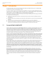
This document explains how to set up and configure the hardware and software for the Syncro™ CS 9286-8e high-
availability direct-attached storage (HA-DAS) solution.
The Syncro CS 9286-8e solution provides fault tolerance capabilities as a key part of a high-availability data storage
system. The Syncro CS 9286-8e solution combines redundant servers, LSI® HA-DAS RAID controllers, computer nodes,
cable connections, common SAS JBOD enclosures, and dual-ported SAS storage devices.
The redundant components and software technologies provide a high-availability system with ongoing service that is
not interrupted by the following events:
The failure of a single internal node does not interrupt service because the solution has multiple nodes with
cluster failover.
An expander failure does not interrupt service because the dual expanders in every enclosure provide redundant
data paths.
A drive failure does not interrupt service because RAID fault tolerance is part of the configuration.
A system storage expansion or maintenance activity can be completed without requiring an interruption of
service because of redundant components, management software, and maintenance procedures.
1.1 Concepts of High-Availability DAS
In terms of data storage and processing, High Availability (HA) means a computer system design that ensures a high
level of operational continuity and data access reliability over a long period of time. High-availability systems are
critical to the success and business needs of small and medium-sized business (SMB) customers, such as retail outlets
and health care offices, who cannot afford to have their computer systems go down. An HA-DAS solution enables
customers to maintain continuous access to and use of their computer system. Shared direct-attached drives are
accessible to multiple servers, thereby maintaining ease of use and reducing storage costs.
A cluster is a group of computers working together to run a common set of applications and to present a single logical
system to the client and application. Failover clustering provides redundancy to the cluster group to maximize up-time
by utilizing fault-tolerant components. In the example of two servers with shared storage that comprise a failover
cluster, when a server fails, the failover cluster automatically moves control of the shared resources to the surviving
server with no interruption of processing. This configuration allows seamless failover capabilities in the event of
planned failover (maintenance mode) for maintenance or upgrade, or in the event of a failure of the CPU, memory, or
other server failures.
Because multiple initiators exist in a clustered pair of servers (nodes) with a common shared storage domain, there is a
concept of device reservations in which physical drives, drive groups, and virtual drives (VDs) are managed by a
selected single initiator. For HA-DAS, I/O transactions and RAID management operations are normally processed by a
single Syncro CS 9286-8e controller, and the associated physical drives, drive groups, and VDs are only visible to that
controller. To assure continued operation, all other physical drives, drive groups, and VDs are also visible to, though
not normally controlled by, the Syncro CS controller. This key functionality allows the Syncro CS 9286-8e solution to
share VDs among multiple initiators as well as exclusively constrain VD access to a particular initiator without the need
for SAS zoning.
Node downtime in an HA system can be either planned and unplanned. Planned node downtime is the result of
management-initiated events, such as upgrades and maintenance. Unplanned node downtime results from events
that are not within the direct control of IT administrators, such as failed software, drivers, or hardware. The Syncro CS
9286-8e solution protects your data and maintains system up-time from both planned and unplanned node
downtime. It also enables you to schedule node downtime to update hardware or firmware, and so on. When you
bring one controller node down for scheduled maintenance, the other node takes over with no interruption of
service.

LSI Corporation
- 5 -
Syncro CS 9286-8e Solution User Guide
March 2013
Chapter 1: Introduction
HA-DAS Terminology
1.2 HA-DAS Terminology
This section defines some additional important HA-DAS terms.
Cache Mirror: A cache coherency term describing the duplication of write-back cached data across two
controllers.
Exclusive Access: A host access policy in which a VD is only exposed to, and accessed by, a single specified server.
Failover: The process in which the management of drive groups and VDs transitions from one controller to the
peer controller to maintain data access and availability.
HA Domain: A type of storage domain that consists of a set of HA controllers, cables, shared disk resources, and
storage media.
Peer Controller: A relative term to describe the HA controller in the HA domain that acts as the failover controller.
Server/Controller Node: A processing entity composed of a single host processor unit or multiple host processor
units that is characterized by having a single instance of a host operating system.
Server Storage Cluster: An HA storage topology in which a common pool of storage devices is shared by two
computer nodes through dedicated Syncro CS 9286-8e controllers.
Shared Access: A host access policy in which a VD is exposed to, and can be accessed by, all servers in the HA
domain.
Virtual Drive (VD): A storage unit created by a RAID controller from one or more physical drives. Although a
virtual drive can consist of multiple drives, it is seen by the operating system as a single drive. Depending on the
RAID level used, the virtual drive might retain redundant data in case of a drive failure.
1.3 Syncro CS 9286-8e Solution Features
The Syncro CS 9286-8e solution supports the following HA features.
Server storage cluster topology, enabled by the following supported operating systems:
— Microsoft® Windows® Server 2008 R2
— Microsoft Windows Server 2012
Clustering/HA services support:
— Microsoft failover clustering
Dual-active HA with shared storage
Controller-to-controller intercommunication over SAS
Write-back cache coherency
CacheCade 1.0 (Read)
Shared and exclusive VD I/O access policies
Operating system boot from the controller (exclusive access)
Controller hardware and property mismatch detection, handling, and reporting
Global hot spare support for all volumes in the HA domain
Planned and unplanned failover modes
CacheVault™ provides cache cached data protection in case of host power loss or server failure
Full MegaRAID® features, with the following exceptions.
— T10 Data Integrity Field (DIF) is not supported.
— Self-encrypting drives (SED) and full disk encryption (FDE) are not supported.
— CacheCade 2.0 (write back) is not supported.
— Dimmer switch is not supported.
— SGPIO sideband signaling for enclosure management is not supported.

LSI Corporation
- 6 -
Syncro CS 9286-8e Solution User Guide
March 2013
Chapter 1: Introduction
Hardware Compatibility
1.4 Hardware Compatibility
The servers, disk drives, and JBOD enclosures you use in the Syncro CS 9286-8e solution must be selected from the list
of approved components that LSI has tested for compatibility. Refer to this web link for the compatibility lists.
http://www.lsi.com/channel/support/pages/interoperability.aspx

LSI Corporation
- 7 -
Syncro CS 9286-8e Solution User Guide
March 2013
Chapter 2: Hardware and Software Setup
Chapter 2: Hardware and Software Setup
This chapter explains how to set up the hardware and software for a Syncro CS 9286-8e solution with two controller
nodes and shared storage. For this implementation you use two standard server modules with Syncro CS 9286-8e
controllers that provide access to disks in one or more JBOD enclosures for reliable, high-access redundancy.
The LSI Syncro CS 9286-8e controller kit includes the following items:
Two Syncro CS 9286-8e controllers
Two CacheVault Flash Module 03 (CVFM03) devices (pre-installed on the controllers)
Two CacheVault Power Module 02 (CVPM02) devices
Two CVPM02 mounting clips and hardware
Two CVPM02 extension cables
Two low-profile brackets
Syncro CS 9286-8e Controller Quick Installation Guide
Syncro CS Resource CD
The hardware configuration for the Syncro CS 9286-8e solution requires the following additional hardware that is not
included in the kit:
Two server modules from the LSI-approved compatibility list. The servers must include network cards.
One or more JBOD enclosures with SAS disk drives from the LSI-approved compatibility list.
A monitor and mouse for each server node.
Network cabling and SAS cabling to connect the servers and JBOD enclosures.
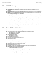
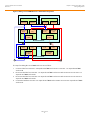
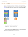
The following figure shows a high-level diagram of a Syncro CS 9286-8e solution connected to a network.

LSI Corporation
- 8 -
Syncro CS 9286-8e Solution User Guide
March 2013
Chapter 2: Hardware and Software Setup
Setting Up a Syncro CS 9286-8e Two-Server Cluster Configuration
Figure 1 Two-Server Syncro CS 9286-8e Configuration
2.1 Setting Up a Syncro CS 9286-8e Two-Server Cluster Configuration
Follow these steps to set up the hardware for a Syncro CS 9286-8e configuration.
1. Unpack the Syncro CS 9286-8e controllers and the CVPM02 modules from the kit and inspect them for damage.
If any components of the kit appear to be damaged, or if any items are missing from the kit, contact your LSI
Customer and Technical Support representative.
2. Turn off the power to the server units, disconnect the power cords, and disconnect any network cables.
3. Remove the covers from the two server units.
Refer to the server documentation for instructions on how to do this.
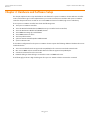
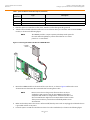
4. Review the Syncro CS 9286-8e jumper settings and change them if necessary. Also note the location of the two
external Mini-SAS SFF8088 connectors J1A4 and J1B1.
You usually do not need to change the default factory settings of the jumpers. The following figure shows the
location of the jumpers and connectors on the controller board.
?
I3#3)
#LIENTWITH
!PPLICATIONS
3ULYDWH/$1
.ETWORK
$.33ERVER
6HUYHU1RGH$
&KDVVLV
3YNCRO#3E
4O P
#ONNECTOR
"OTTOM
#ONNECTOR
6HUYHU1RGH%
&KDVVLV
3YNCRO#3E
4O P
#ONNECTOR
"OTTOM
#ONNECTOR
([WHUQDO-%2'6$6'ULYH(QFORVXUH
%XPANDER!
#ONNECTOR
#ONNECTOR
%XPANDER"
#ONNECTOR
#ONNECTOR
3XEOLF/RFDO$UHD1HWZRUN/$1
I3#3)
#LIENTWITH
!PPLICATIONS
I3#3)
#LIENTWITH
!PPLICATIONS
.OTE %XPANDER!CONNECTSTO0ORT!OFTHE3!3DRIVES
%XPANDER"CONNECTSTO0ORT"OFTHE3!3DRIVES
3!33INGLE,ANES
3!3&OUR,ANES
#ONNECTOR
#ONNECTOR

LSI Corporation
- 9 -
Syncro CS 9286-8e Solution User Guide
March 2013
Chapter 2: Hardware and Software Setup
Setting Up a Syncro CS 9286-8e Two-Server Cluster Configuration
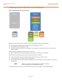
The CVFM03 module comes preinstalled on the Syncro CS controller; however, the module is not included in the
following figure so that you can see all of the connectors and headers on the controller board. Figure 3 and
Figure 4 show the controller with the CVFM03 module installed.
Figure 2 Syncro CS 9286-8e Jumpers and Connectors
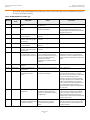
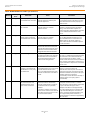
In the figure, Pin 1 is highlighted in red for each jumper. The following table describes the jumpers and connectors on
the Syncro CS 9286-8e controller.
Table 1 Syncro CS 9286-8e Controller Jumpers
Jumper/
Connector
Type Description
J1A4 External SFF-8088 4-port SAS connector In the cabling figures later in this chapter, this connector is called the
"top" connector.
J1B1 External SFF-8088 4-port SAS connector In the cabling figures later in this chapter, this connector is called the
"bottom" connector.
J1A1 Write-Pending LED header 2-pin connector
Connects to an LED that indicates when the data in the cache has yet to
be written to the storage devices. Used when the write-back feature is
enabled.
J1A3 Global Drive Fault LED header 2-pin connector
Connects to an LED that indicates whether a drive is in a fault condition.
J2A1 Activity LED header 2-pin connector
Connects to an LED that indicates activity on the drives connected to
the controller.
J2A2 Advanced Software Options Hardware Key
header
3-pin header
Enables support for the Advanced Software Options features.
J2A4
I
2
O Mode jumper
2-pin connector
Installing this jumper causes the RAID controller to run in I
2
O mode.
The default, recommended mode of operation is without the shunt and
running in Fusion mode.
J4A1 Serial EEPROM 2-pin connector
Provides controller information, such as the serial number, revision, and
manufacturing date. The default is no shunt installed.
3_00922-01
J1A1
J1A3
J2A1
J2A2
J4A1 J4A2 J5A1 J6A1
J2A4
J2B1
J1A4
J1B1
J5B1
Ports
0 - 3
Ports
4 - 7

LSI Corporation
- 10 -
Syncro CS 9286-8e Solution User Guide
March 2013
Chapter 2: Hardware and Software Setup
Setting Up a Syncro CS 9286-8e Two-Server Cluster Configuration
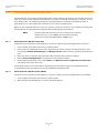
5. Place the Syncro CS controller on a flat, clean, static-free surface after grounding yourself.
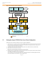
6. Take the cable included with the kit and insert one end of it into the 9-pin connector on the remote CVPM02
module, as shown in the following figure.
NOTE The CVPM02 module is a super-capacitor pack that provides power for
the cache offload capability to protect cached data in case of host
power loss or server failure.
Figure 3 Connecting the Cable to the Remote CVPM02 Module
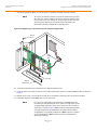
7. Mount the CVPM02 module to the inside of the server chassis, as shown in Figure 4. Refer to the server
documentation to determine the exact method of mounting the module.
NOTE Because server chassis design varies from vendor to vendor, no
standard mounting option exists for the CVPM02 module that is
compatible with all chassis configurations. Authorized resellers and
chassis manufacturers might have recommendations for the location
of the power module to provide the most flexibility within various
environments.
8. Make sure that the power to the server is still turned off, that the power cords are unplugged, and that the chassis
is grounded and has no AC power.
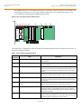
9. Insert the Syncro CS 9286-8e controller into a PCIe slot on the motherboard, as shown in the following figure.
J4A2 LSI Test header Reserved for LSI use.
J5A1 Serial UART connector for the expander Reserved for LSI use.
J6A1 Serial UART connector for the expander Reserved for LSI use.
Table 1 Syncro CS 9286-8e Controller Jumpers (Continued)
Jumper/
Connector
Type Description
3_01853-00
CVPM02
Module
CVFM03
Module
J2A1

LSI Corporation
- 11 -
Syncro CS 9286-8e Solution User Guide
March 2013
Chapter 2: Hardware and Software Setup
Setting Up a Syncro CS 9286-8e Two-Server Cluster Configuration
Press down gently, but firmly, to seat the Syncro CS 9286-8e controller correctly in the slot.
NOTE The Syncro CS 9286-8e controller is a PCIe x8 card that can operate in
x8 or x16 slots. Some x16 PCIe slots support only PCIe graphics cards;
if you install a Syncro CS 9286-8e in one of these slots, the controller
will not function. Refer to the motherboard documentation for
information about the configuration of the PCIe slots.
Figure 4 Installing the Syncro CS 9286-8e Controller and Connecting the Cable
10. Secure the controller to the computer chassis with the bracket screw.
11. Insert the other 9-pin cable connector on the cable into the J2A1 connector on the CVFM03 module, as shown in
Figure 3.
12. Repeat step 5 to step 11 to install the second Syncro CS 9286-8e controller in the second server module.
13. Install SAS disk drives in the JBOD enclosure or enclosures.
NOTE In a Syncro CS configuration, the expanders in the JBOD enclosure
must have two four-lane IN ports. As an option, the expanders can be
configured with a third four-lane port to connect to other cascaded
expanders, as shown in Figure 1. JBOD enclosures with dual expanders
can support split mode or unified mode. For fault-tolerant cabling
configurations, you typically configure the JBOD enclosure in unified
mode. (Check with the JBOD enclosure vendor to determine the
appropriate settings).
Edge of
Motherboard
PCIe Slot
Bracket
Screw
Press
Here
Press
Here
3_01852-00

LSI Corporation
- 12 -
Syncro CS 9286-8e Solution User Guide
March 2013
Chapter 2: Hardware and Software Setup
Setting Up a Syncro CS 9286-8e Two-Server Cluster Configuration
Refer to the drive documentation to determine any pre-installation configuration requirements. Be sure to use
SAS disk drives that are listed on the LSI-approved list. (To view this list, follow the URL listed in Section 1.4,
Hardware Compatibility.)
14. If necessary, install network boards in the two server modules and install the cabling between them.
15. Reinstall the covers of the two servers.
16. Install the two server modules and the JBOD enclosure in an industry-standard cabinet, if appropriate, following
the manufacturer’s instructions.
17. Use SAS cables to connect the two external connectors on the Syncro CS 9286-8e controller to the JBOD
enclosure or enclosures. See Figure 2 to view the location of the external connectors.
See Section 2.2, Cabling Configurations, for specific cabling instructions for one or two JBOD enclosures.
18. Reconnect the power cords and turn on the power to the servers and the JBOD enclosure or enclosures.
Follow the generally accepted best practice by turning on the power on to the JBOD enclosure before you power
the two servers. If you power the servers before you power the JBOD enclosure, the servers might not recognize
the disk drives.
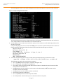
When the servers boot, a BIOS message appears. The firmware takes several seconds to initialize. The
configuration utility prompt times out after several seconds. The second portion of the BIOS message shows the
Syncro CS 9286-8e number, firmware version, and cache SDRAM size. The numbering of the controllers follows
the PCI slot scanning order used by the host motherboard.
19. Configure the groups and the virtual drives on the two controllers.
For specific instructions, see Section 3.3, Creating Virtual Drives on the Controller Nodes. You can use WebBIOS,
MegaCLI64, or MegaRAID Storage Manager to create the groups and virtual drives.
20. Install the operating system driver on both server nodes.
You must install the software drivers first, before installing the operating system.
You can view the supported operating systems and download the latest drivers for the Syncro CS controllers from
the LSI website at http://www.lsi.com/support/Pages/download-search.aspx. Access the download center, and
follow the steps to download the appropriate driver.
Refer to the MegaRAID SAS Device Driver Installation User Guide on the Syncro CS Resource CD for more
information about installing the driver. Be sure to review the readme file that accompanies the driver.
21. Install the operating system on both server nodes, following the instructions from Microsoft. The following
operating systems are supported:
— Microsoft Windows Server 2012
— Microsoft Windows Server 2008 R2
NOTE Support for clustered RAID controllers is not enabled by default in
Microsoft Windows Server 2012 or Microsoft Windows Server 2008 R2.
To enable support for this feature, consult with your server vendor. For
additional information visit the Cluster in a Box Validation Kit for
Windows Server site on the Microsoft Windows Server TechCenter
website.
Be sure to use the latest service packs that are provided by Microsoft. You have two options for installing the
operating system for each controller node:
— Install it on a private volume connected to the system-native storage controller. The recommended best
practice is to install the operating system on this private volume because the disks in the clustering
configuration cannot see this volume. Therefore, no danger exists of accidentally overwriting the operating
system disk when you set up clustering.
— Install it on an exclusive virtual drive connected to the Syncro CS 9286-8e controller. Exclusive host access is
required for a boot volume so the volume is not overwritten accidentally when you create virtual drives for
data storage. For instructions on creating exclusive virtual drives using the WebBIOS utility, see Section 3.3.1,
Creating Shared or Exclusive VDs with the WebBIOS Utility.

LSI Corporation
- 13 -
Syncro CS 9286-8e Solution User Guide
March 2013
Chapter 2: Hardware and Software Setup
Cabling Configurations
NOTE The Syncro CS 9286-8e solution does not support booting from a
shared operating system volume.
22. Install the Failover Cluster feature on both servers, following the instructions in the Microsoft documentation.
2.2 Cabling Configurations
This section has information about initially setting up a Syncro CS configuration with one or two JBOD enclosures. It
also explains how to add a second JBOD enclosure to an operational single-JBOD configuration without interrupting
service on the configuration.
System throughput problems can occur if you use the wrong kind of SAS cables. To minimize the potential for
problems, use high-quality cables that meet SAS 2.1 standards and that are less than 6 meters long. See the list of
approved cables and vendors on the web link listed at the end of Section 1.4, Hardware Compatibility.
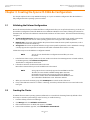
The following figure shows the SAS cable connections for a two-controller-node configuration with a single JBOD
enclosure.
NOTE In the figures in this section, Top Connector means the external
connector closest to the bracket screw support end of the controller
bracket (connector J1A4 in Figure 2). Bottom Connector means the
other external connector (connector J1B1 in Figure 2).
Figure 5 Two-Controller-Node Configuration with Single JBOD Enclosure
The cross-connections between the controllers provide redundant paths that safeguard against expander, cable, or
expander failure.
To retain consistent device reporting, the corresponding port numbers for both controllers must be connected to a
common enclosure expander. In this example, the top connector on each controllers is connected to Expander A and
the bottom connector on each controller is connected to Expander B.
?
6HUYHU1RGH$
&KDVVLV
3YNCRO#3E
4O P
#ONNECTOR
"OTTOM
#ONNECTOR
6HUYHU1RGH%
&KDVVLV
3YNCRO#3E
4O P
#ONNECTOR
"OTTOM
#ONNECTOR
([WHUQDO-%2'6$6'ULYH(QFORVXUH
%XPANDER!
#ONNECTOR
#ONNECTOR
%XPANDER"
#ONNECTOR
#ONNECTOR
#ONNECTOR
#ONNECTOR

LSI Corporation
- 14 -
Syncro CS 9286-8e Solution User Guide
March 2013
Chapter 2: Hardware and Software Setup
Cabling Configurations
The following figure shows the SAS cable connections for a two-controller-node configuration with two JBOD
enclosures.
NOTE To save space, the figure does not show the disk drives that are in the
JBOD enclosures.
Figure 6 Two-Controller-Node Configuration with Dual JBOD Enclosures
The recommended method shown in the preceding figure is preferable to simply daisy-chaining a second JBOD
enclosure from the single-JBOD configuration shown in Figure 5, because a single power failure in the first JBOD
enclosure could interrupt all data access. Instead, connect the second Syncro CS controller envisioning the JBOD
enclosures in reverse order. The resulting top-down/bottom-up cabling approach shown in the preceding figure is
preferred because it assures continued access to operating drives if either of the JBOD enclosures fails or is removed.
The following figure shows how to hot-add a second JBOD enclosure to an existing two-server cluster without
interrupting service on the HA configuration.
NOTE To save space, the figure does not show the disk drives that are in the
JBOD enclosures.
?
6HUYHU1RGH$
6\QFUR&6H
4OP
#ONNECTOR
"OTTOM
#ONNECTOR
6HUYHU1RGH%
6\QFUR&6H
'ULYH(QFORVXUH$
([SDQGHU$
#ONNECTOR
)N
#ONNECTOR
)N
#ONNECTOR
/UT
([SDQGHU%
#ONNECTOR
)N
#ONNECTOR
)N
'ULYH(QFORVXUH%
([SDQGHU$
#ONNECTOR
/UT
([SDQGHU%
#ONNECTOR
/UT
#ONNECTOR
)N
#ONNECTOR
)N
#ONNECTOR
)N
#ONNECTOR
)N
#ONNECTOR
/UT
4OP
#ONNECTOR
"OTTOM
#ONNECTOR

LSI Corporation
- 15 -
Syncro CS 9286-8e Solution User Guide
March 2013
Chapter 2: Hardware and Software Setup
Cabling Configurations
Figure 7 Adding a Second JBOD Enclosure - Redundant Configuration
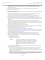
The steps for adding the second JBOD enclosure are as follows:
1. Connect a link from connector 2 on Expander B of JBOD enclosure A to connector 1 on expander B of JBOD
enclosure B.
2. Disconnect the link from connector 1 on expander A of JBOD enclosure A and reconnect it to connector 1 on
expander A of JBOD enclosure B.
3. Disconnect the link from connector 0 on expander A of JBOD enclosure A and reconnect it to connector 0 on
expander A of JBOD enclosure B.
4. Connect the link from connector 2 on expander A of JBOD enclosure B to connector 0 on expander A of JBOD
enclosure A.
?
6HUYHU1RGH$
6\QFUR&6H
6HUYHU1RGH%
6\QFUR&6H
'ULYH(QFORVXUH$
([SDQGHU$
#ONNECTOR
)N
#ONNECTOR
)N
#ONNECTOR
/UT
([SDQGHU%
#ONNECTOR
)N
#ONNECTOR
)N
#ONNECTOR
/UT
'ULYH(QFORVXUH%
([SDQGHU$
#ONNECTOR
/UT
([SDQGHU%
#ONNECTOR
/UT
4OP
#ONNECTOR
"OTTOM
#ONNECTOR
#ONNECTOR
)N
#ONNECTOR
)N
#ONNECTOR
)N
#ONNECTOR
)N
4OP
#ONNECTOR
"OTTOM
#ONNECTOR

LSI Corporation
- 16 -
Syncro CS 9286-8e Solution User Guide
March 2013
Chapter 3: Creating the Syncro CS 9286-8e Configuration
Validating the Failover Configuration
Chapter 3: Creating the Syncro CS 9286-8e Configuration
This chapter explains how to set up HA-DAS clustering on a Syncro CS 9286-8e configuration after the hardware is
fully configured and the operating system is installed.
3.1 Validating the Failover Configuration
Microsoft recommends that you validate the failover configuration before you set up failover clustering. To do this, run
the Validate a Configuration wizard for Windows Server 2008 R2 or Windows Server 2012, following the instructions
from Microsoft. The tests in the validation wizard include simulations of cluster actions. The tests fall into the following
categories:
System Configuration tests. These tests analyze whether the two server modules meet specific requirements,
such as running the same version of the operating system version using the same software updates.
Network tests. These tests analyze whether the planned cluster networks meet specific requirements, such as
requirements for network redundancy.
Storage tests. These tests analyze whether the storage meets specific requirements, such as whether the storage
correctly supports the required SCSI commands and handles simulated cluster actions correctly.
Follow these steps to run the Validate a Configuration wizard.
NOTE You can also run the Validate a Configuration wizard after you create
the cluster.
1. In the failover cluster snap-in, in the console tree, make sure Failover Cluster Management is selected and then,
under Management, click Validate a Configuration.
The Validate a Configuration wizard starts.
2. Follow the instructions for the wizard and run the tests.
Microsoft recommends that you run all available tests in the wizard.
NOTE Storage Spaces does not currently support Clustered RAID controllers.
Therefore, do not include the Validate Storage Spaces Persistent
Reservation storage test in the storage test suite. For additional
information, visit the Cluster in a Box Validation Kit for Windows Server
site on the Microsoft Windows Server TechCenter website.
3. When you arrive at the Summary page, click View Reports to view the results of the tests.
4. If any of the validation tests fails or results in a warning, correct the problems that were uncovered and run the
test again.
3.2 Creating the Cluster
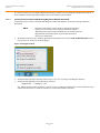
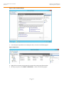
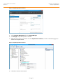
The Microsoft Server 2012 operating system installation does not enable the clustering feature by default. Follow
these steps to view the system settings, and, if necessary, to enable clustering.
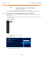
1. From the desktop, launch Server Manager.
2. Click Manage and select Add Roles and Features.
3. If the Introduction box is enabled (and appears), click Next.
4. In the Select Installation Type box, select Role Based or Feature Based.

LSI Corporation
- 17 -
Syncro CS 9286-8e Solution User Guide
March 2013
Chapter 3: Creating the Syncro CS 9286-8e Configuration
Creating Virtual Drives on the Controller Nodes
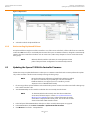
5. In the Select Destination Server box, select the system and click Next.
6. In the Select Server Roles list, click Next to present the Features list.
7. Make sure that failover clustering is installed, including the tools. If necessary, run the Add Roles and Features
wizard to install the features dynamically from this user interface.
8. If the cluster nodes need to support I/O as iSCSI targets, expand File and Storage Services, File Services and
check for iSCSI Target Server and Server for NFS.
The Server Manager includes a configuration validator under Server Manager> Tools> Failover Cluster
Manager…Validate a Configuration. Refer to the Microsoft documentation for more detailed information.
During creation of the cluster, Windows automatically defines and creates the quorum, a configuration database that
contains metadata required for the operation of the cluster. To create a shared VD for the quorum, see the instructions
in Section 3.3, Creating Virtual Drives on the Controller Nodes.
NOTE The recommended best practice is to create a small redundant VD for
the quorum. A size of 500 MB is adequate for this purpose.
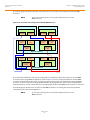
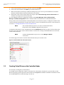
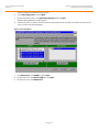
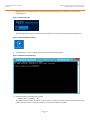
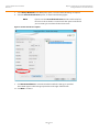
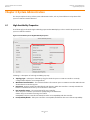
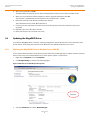
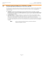
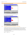
To determine if the cluster is active, run MSM and look at the Dashboard tab for the controller. The first of two nodes
that boots shows the cluster status as Inactive until the second node is running and the MSM dashboard on the first
node has been refreshed.
NOTE To refresh the MSM dashboard, press F5 or select Manage > Refresh
on the menu.
The following figure shows the controller dashboard with Active peer controller status.
Figure 8 Controller Dashboard: Active Cluster Status
3.3 Creating Virtual Drives on the Controller Nodes
The next step is creating VDs on the disk drives.
The HA-DAS cluster configuration requires a minimum of one shared VD to be utilized as a quorum disk to enable
Microsoft operating system support for clusters. Refer to the MegaRAID SAS Software User Guide for information about
the available RAID levels and the advantages of each one.

LSI Corporation
- 18 -
Syncro CS 9286-8e Solution User Guide
March 2013
Chapter 3: Creating the Syncro CS 9286-8e Configuration
Creating Virtual Drives on the Controller Nodes
As explained in the instructions in the following sections, VDs created for storage in an HA-DAS configuration must be
shared. If you do not designate them as shared, the VDs are visible only from the controller node from which they
were created.
You can use the WebBIOS pre-boot utility to create the VDs. You can also use the LSI MegaRAID Storage Manager
(MSM) utility or the MegaCLI utility to create VDs after Windows has booted. Refer to the MegaRAID SAS Software User
Guide for complete instructions on using these utilities.
3.3.1 Creating Shared or Exclusive VDs with the WebBIOS Utility
To coordinate the configuration of the two controller nodes, both nodes must be booted into the WebBIOS pre-boot
utility. The two nodes in the cluster system boot simultaneously after power on, so you must rapidly access both
consoles. One of the systems is used to create the VDs; the other system simply remains in the pre-boot utility. This
approach keeps the second system in a state that does not fail over while the VDs are being created on the first
system.
NOTE The WebBIOS utility cannot see boot sectors on the disks. Therefore,
be careful not to select the boot disk for a VD. Preferably, unshare the
boot disk before doing any configuration with the pre-boot utility. To
do this, select Logical Drive Properties and deselect the Shared
Virtual Disk property.
Follow these steps to create VDs with the WebBIOS utility.
1. When prompted during the POST on the two systems, use the keyboard to access the WebBIOS pre-boot BIOS
utility (on both systems) by pressing Ctrl-H.
Respond quickly, because the system boot times are very similar and the time-out period is short. When both
controller nodes are running the WebBIOS utility, follow these steps to create RAID 5 arrays.
NOTE To create a RAID 0, RAID 1, or RAID 6 array, modify the instructions to
select the appropriate number of disks.
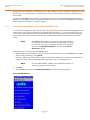
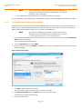
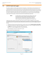
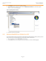
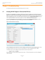
2. Click Start.
3. On the WebBIOS main page, click Configuration Wizard, as shown in the following figure.
Figure 9 WebBIOS Main Page

LSI Corporation
- 19 -
Syncro CS 9286-8e Solution User Guide
March 2013
Chapter 3: Creating the Syncro CS 9286-8e Configuration
Creating Virtual Drives on the Controller Nodes
The first Configuration Wizard window appears.
4. Select Add Configuration and click Next.
5. On the next wizard screen, select Manual Configuration and click Next.
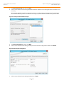
The Drive Group Definition window appears.
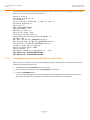
6. In the Drives panel on the left, select the first drive, then hold down the Ctrl key and select more drives for the
array, as shown in the following figure.
Figure 10 Selecting Drives
7. Click Add To Array, click ACCEPT, and click Next.
8. On the next screen, click Add to SPAN, then click Next.
9. On the next screen, click Update Size.

LSI Corporation
- 20 -
Syncro CS 9286-8e Solution User Guide
March 2013
Chapter 3: Creating the Syncro CS 9286-8e Configuration
Creating Virtual Drives on the Controller Nodes
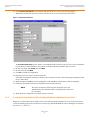
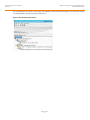
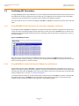
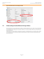
10. Select Provide Shared Access on the bottom left of the window, as shown in the following figure.
Alternatively, deselect this option to create an exclusive VD as a boot volume for this cluster node.
Figure 11 Virtual Drive Definition
The Provide Shared Access option enables a shared VD that both controller nodes can access. If you uncheck this
box, the VD has a status of Exclusive, and only the controller node that created this VD can access it.
11. On this same page, click Accept, then click Next.
12. On the next page, click Next.
13. Click Ye s to accept the configuration.
14. Repeat the previous steps to create the other VDs.
As the VDs are configured on the first controller node, the other controller node’s drive listing is updated to reflect
the use of the drives.
15. When prompted, click Ye s to save the configuration, and click Ye s to confirm that you want to initialize it.
16. Define hot spare disks for the VDs to maximize the level of data protection.
NOTE The Syncro CS 9286-8e solution supports global hot spares and
dedicated hot spares. Global hot spares are global for the cluster, not
for a controller.
17. When all VDs are configured, reboot both systems as a cluster.
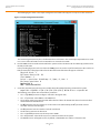
3.3.2 Creating Shared or Exclusive VDs with MegaCLI64.exe on Windows Server 2012
MegaCLI is a command-line-driven utility used to create and manage VDs. MegaCLI can run in any directory on the
server. The following procedure assumes that a current copy of the 64-bit Windows version of MegaCLI is located on
the server in c:\lsi\cli.
Page is loading ...
Page is loading ...
Page is loading ...
Page is loading ...
Page is loading ...
Page is loading ...
Page is loading ...
Page is loading ...
Page is loading ...
Page is loading ...
Page is loading ...
Page is loading ...
Page is loading ...
Page is loading ...
Page is loading ...
Page is loading ...
Page is loading ...
Page is loading ...
Page is loading ...
Page is loading ...
Page is loading ...
Page is loading ...
Page is loading ...
Page is loading ...
Page is loading ...
Page is loading ...
Page is loading ...
Page is loading ...
Page is loading ...
Page is loading ...
Page is loading ...
Page is loading ...
-
 1
1
-
 2
2
-
 3
3
-
 4
4
-
 5
5
-
 6
6
-
 7
7
-
 8
8
-
 9
9
-
 10
10
-
 11
11
-
 12
12
-
 13
13
-
 14
14
-
 15
15
-
 16
16
-
 17
17
-
 18
18
-
 19
19
-
 20
20
-
 21
21
-
 22
22
-
 23
23
-
 24
24
-
 25
25
-
 26
26
-
 27
27
-
 28
28
-
 29
29
-
 30
30
-
 31
31
-
 32
32
-
 33
33
-
 34
34
-
 35
35
-
 36
36
-
 37
37
-
 38
38
-
 39
39
-
 40
40
-
 41
41
-
 42
42
-
 43
43
-
 44
44
-
 45
45
-
 46
46
-
 47
47
-
 48
48
-
 49
49
-
 50
50
-
 51
51
-
 52
52


LSI Syncro CS 9286-8e User guide
- Category
- Interface cards/adapters
- Type
- User guide
Ask a question and I''ll find the answer in the document
Finding information in a document is now easier with AI
Related papers
-
LSI Syncro CS 9286-8e Solution User guide
-
-
-
-
-
-
-
-
-
Other documents
-
Broadcom MegaRAID SAS Software User guide
-
ACTi EN-2126JS6-SQX User manual
-
Lenovo ThinkServer RD240 Software User's Manual
-
-
Supermicro BTR-0012L-0000-LSI User manual
-
Lenovo ThinkServer RD430 Software User's Manual
-
NEC Express5800/120Li User guide
-
Supermicro AOC-USAS-H4IR User guide
-
Lenovo ThinkServer RD650 User manual
-