Alpha innotec RBE Owner's manual
- Category
- Heat pumps
- Type
- Owner's manual

Subject to technical change without notice.
83032600bUK – Translation into English of the original German operating manual
Operating Manual
RBE
Room control unit
i bh

2
Contents
INFORMATION FOR USERS AND QUALIFIED
PERSONNEL
PLEASE READ FIRST .................................................................................................... 2
SYMBOLS ........................................................................................................................2
INTENDED USE .............................................................................................................3
DISCLAIMER ................................................................................................................... 3
CUSTOMER SERVICE ................................................................................................... 3
WARRANTY
/
GUARANTEE ........................................................................................3
DISPOSAL........................................................................................................................3
SCOPE OF SUPPLY .......................................................................................................3
GENERAL ......................................................................................................................... 3
INSTALLATION ..............................................................................................................4
ELECTRICAL CONNECTION ......................................................................................5
Connecting the communications and power supply .............................. 5
TECHNICAL DATA ........................................................................................................5
COMMISSIONING AND CONFIGURATION OF THE RBE ROOM CONTROL
UNIT ...........................................................................................................................6
ROOM CONTROL UNIT SETTINGS .........................................................................6
Inuencing factor RT ...........................................................................................6
Cooling release ......................................................................................................7
Heat distribution system .................................................................................... 7
ADJUSTMENT OF THE RETURN SETPOINT TEMPERATURE UNDER
ROOM TEMPERATURE INFLUENCE ................................................................7
LAYOUT AND HANDLING .........................................................................................8
START SCREEN ..............................................................................................................8
Functions and information in the start screen: ..........................................8
MAIN MENU ................................................................................................................... 9
Basic layout: ............................................................................................................9
Contents of the submenu: ................................................................................. 9
FAULTS .......................................................................................................................... 11
83032600bUK– Translation into English of the original German operating manual – Subject to technical change without notice.
Symbols
Information for users.
Information or instructions for qualied personnel.
DANGER!
Risk of fatal electric shock!
DANGER!
Indicates imminent danger resulting in severe injuries or death.
WARNING!
Indicates a potentially dangerous situation, which could result in
severe injuries or death.
CAUTION!
Indicates a potentially dangerous situation, which could result in
moderate or slight injuries.
ATTENTION
Indicates a potentially dangerous situation, which could result in
property damage.
NOTE
Emphasised information
Reference to other sections of the operating manual.
Reference to other documents of the manufacturer.
€
ENERGY SAVING TIP
Indicates suggestions that help to save energy, raw materials
and costs.
Please read rst
This operating manual provides important information on handling the
unit. It is an integral part of the product and must be kept ready to hand
in the immediate vicinity of the unit. It must remain available throughout
the entire service life of the unit. It must be handed over to subsequent
owners or users of the unit.
Read this operating manual before starting any work on or with the unit.
Especially the chapter on safety. Follow all instructions in full and unre-
servedly.
This operating manual may contain descriptions, which seem incompre-
hensible or unclear. If you have any questions or if any details are unclear,
contact the factory customer service department or the manufacturer's
local partner.
This operating manual is intended only for persons assigned to work on
or with the unit. Treat all constituent parts condentially. They are pro-
tected by copyright. They may not be reproduced, transmitted, copied,
stored in electronic systems or translated into another language, either
wholly or in part, without the express written permission of the manu-
facturer.

383032600bUK– Translation into English of the original German operating manual – Subject to technical change without notice.
Intended use
As a remote control and remote display for certain functions of the heat
pump controller
•
only in conjunction with the heat pump controller
•
for selected products only (for further information, please refer to
the current price list)
Disclaimer
The manufacturer is not liable for any damage or losses resulting from
use of the unit which is not its intended use.
The manufacturer's liability also expires:
•
if work is carried out on the unit and its components contrary to the
instructions in this operating manual.
•
if work is carried out improperly on the unit and its components.
•
if work is carried out on the unit which is not described in this
operating manual, and this work has not been explicitly approved by
the manufacturer in writing.
•
if the unit or components in the unit are changed, modied or
removed without the explicit written consent of the manufacturer.
Customer service
For technical information please contact your local qualied installer or
the manufacturer's local partner.
DE: www.alpha-innotec.de
EU: www.alpha-innotec.eu
Warranty
/
Guarantee
For warranty and guarantee provisions, please refer to your purchase
documents.
NOTE
Please contact your dealer about all matters concerning warranties and
guarantees.
Disposal
When withdrawing the old unit from service, comply with the relevant
local laws, guidelines, directives and standards concerning the recovery,
reuse, recycling and disposal of components.
Scope of supply
Allgemeines
Mit RMU 40 können Sie Ihre NIBE-Wärmepumpe von ei-
nem Raum im Gebäude aus steuern und überwachen.
Inhalt
LEK
LEK
2 Schrauben1 Abstandsstück
aus Kunststoff
1 RMU 40
Installationsmöglichkeiten
RMU 40 kann auf unterschiedliche Weise installiert wer-
den. Einige Varianten werden im Folgenden aufgeführt.
1
1
2
1
2
1
2
3
1
2
508b
508b
508b
508b
508b
508b
508b
%7
%7
Raumtemperaturfühler
RMU 40 enthält einen Raumfühler, der dieselbe Funkti-
onsweise wie der Raumfühler im Lieferumfang der Wär-
mepumpe (BT50) aufweist.
So kann gewählt werden, welchen Raumfühler die Wär-
mepumpe zur Anzeige und eventuellen Regelung der
Raumtemperatur verwenden soll.
Der Raumfühler erfüllt bis zu drei Funktionen:
1.
Anzeige der aktuellen Raumtemperatur im Wär-
mepumpendisplay.
2.
Ermöglicht die Änderung der Raumtemperatur in
°C.
3.
Ermöglicht das Aufwerten bzw. Stabilisieren der
Raumtemperatur.
Montieren Sie den Fühler an einem neutralen Ort, an
dem die eingestellte Temperatur gewünscht wird. Als
geeigneter Ort kommt z.B. eine freie Innenwand im
Flur ca. 1,5 m über dem Fußboden in Frage. Der Fühler
darf nicht an der Messung einer korrekten Raumtem-
peratur gehindert werden, z.B. durch die Anbringung
in einer Nische, zwischen Regalen, hinter einer Gardi-
ne, über bzw. in der Nähe einer Wärmequelle, in ei-
nem Luftzugbereich von der Außentür oder in direkter
Sonneneinstrahlung. Auch geschlossene Heizkörper-
thermostate können Probleme hervorrufen.
Wenn der Fühler zum Ändern der Raumtemperatur in
°C und bzw. oder zum Aufwerten bzw. Stabilisieren
der Raumtemperatur genutzt werden soll, muss er in
Menü 1.9.4 der Wärmepumpe aktiviert werden.
ACHTUNG!
Wenn der Raumfühler in einem Raum mit
Fußbodenheizung platziert ist, sollte er ledig-
lich eine Anzeigefunktion besitzen, jedoch
keine Regelungsfunktion für die Raumtempe-
ratur.
21
Deutsch, Installateurhandbuch - RMU 40
DE
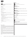
1 RBE 1 Surface-
mounted frame
made of plastic
2 Screws
General
The RBE can be used to read out, change and optimise the most impor-
tant parameters and operating data conveniently in the home (e.g.
adjustment of the heating temperature or hot water temperature, read-
ing out temperatures).
Allgemeines
Mit RMU 40 können Sie Ihre NIBE-Wärmepumpe von ei-
nem Raum im Gebäude aus steuern und überwachen.
Inhalt
LEK
LEK
2 Schrauben1 Abstandsstück
aus Kunststoff
1 RMU 40
Installationsmöglichkeiten
RMU 40 kann auf unterschiedliche Weise installiert wer-
den. Einige Varianten werden im Folgenden aufgeführt.
1
1
2
1
2
1
2
3
1
2
508b
508b
508b
508b
508b
508b
508b
%7
%7
Raumtemperaturfühler
RMU 40 enthält einen Raumfühler, der dieselbe Funkti-
onsweise wie der Raumfühler im Lieferumfang der Wär-
mepumpe (BT50) aufweist.
So kann gewählt werden, welchen Raumfühler die Wär-
mepumpe zur Anzeige und eventuellen Regelung der
Raumtemperatur verwenden soll.
Der Raumfühler erfüllt bis zu drei Funktionen:
1.
Anzeige der aktuellen Raumtemperatur im Wär-
mepumpendisplay.
2.
Ermöglicht die Änderung der Raumtemperatur in
°C.
3.
Ermöglicht das Aufwerten bzw. Stabilisieren der
Raumtemperatur.
Montieren Sie den Fühler an einem neutralen Ort, an
dem die eingestellte Temperatur gewünscht wird. Als
geeigneter Ort kommt z.B. eine freie Innenwand im
Flur ca. 1,5 m über dem Fußboden in Frage. Der Fühler
darf nicht an der Messung einer korrekten Raumtem-
peratur gehindert werden, z.B. durch die Anbringung
in einer Nische, zwischen Regalen, hinter einer Gardi-
ne, über bzw. in der Nähe einer Wärmequelle, in ei-
nem Luftzugbereich von der Außentür oder in direkter
Sonneneinstrahlung. Auch geschlossene Heizkörper-
thermostate können Probleme hervorrufen.
Wenn der Fühler zum Ändern der Raumtemperatur in
°C und bzw. oder zum Aufwerten bzw. Stabilisieren
der Raumtemperatur genutzt werden soll, muss er in
Menü 1.9.4 der Wärmepumpe aktiviert werden.
ACHTUNG!
Wenn der Raumfühler in einem Raum mit
Fußbodenheizung platziert ist, sollte er ledig-
lich eine Anzeigefunktion besitzen, jedoch
keine Regelungsfunktion für die Raumtempe-
ratur.
21
Deutsch, Installateurhandbuch - RMU 40
DE
€
ENERGY SAVING TIP
Unnecessarily high ow temperatures in heating or hot water
mode reduce the eciency of the system, increase stoppage
and pipe losses and therefore increase running costs. With
the room control unit, these temperatures can be set or
optimised to the user's own comfort requirements, easily and
conveniently in the home. To do this, lower the temperatures
gradually to determine your own personal comfort settings
The RBE can be used for control with room temperature inuence.
The RBE displays the heat pump functions accordingly in the relevant
menu:
•
Heating
•
Hot water
•
Cooling
•
Ventilation
•
Solar thermal energy
•
Swimming pool
•
Photovoltaics
In order to equip the heat pump control with a room control unit, a
control unit with RS485 interface is required:
RS485 / LIN-BUS
Control unit with RS485 and LIN-BUS interface
refer to the operating manual of the heat pump controller.

4 83032600bUK– Translation into English of the original German operating manual – Subject to technical change without notice.
Installation
Install the RBE in the main room (reference room, e.g. living room),
approx. 1.5 m above the oor. The sensor (integrated in the RBE) must
be located so that it can measure the correct room temperature, and
not where it can be obstructed, e.g. do not attach it in a niche, between
shelves, behind a curtain or near a heat source, a draught area of the
external door or in direct sunlight. Closed radiator thermostats for room
temperature-controlled heating systems can also cause problems.
Radiator or underoor heating valves of the main room must be kept
permanently open for room temperature controlled systems.
Only one RBE can be connected for each heat pump.
NOTE
A screwdriver, slot head type, size: 0.4 x 2.0mm is required to install the
RBE
NOTE
The RBE cannot be mounted directly on a wall, as a terminal protrudes at
the rear.
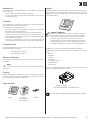
Therefore, there are two installation options for the RBE:
For installation with a standard cavity or ush-type box (provided on
site by the customer, screw spacing 60mm). Only use Spax screws (not
included with the RBE).
or for installation using a surface-mounted frame for surface-mounted
installation (included with the RBE)
Allgemeines
Mit RMU 40 können Sie Ihre NIBE-Wärmepumpe von ei-
nem Raum im Gebäude aus steuern und überwachen.
Inhalt
LEK
LEK
2 Schrauben1 Abstandsstück
aus Kunststoff
1 RMU 40
Installationsmöglichkeiten
RMU 40 kann auf unterschiedliche Weise installiert wer-
den. Einige Varianten werden im Folgenden aufgeführt.
1
1
2
1
2
1
2
3
1
2
508b
508b
508b
508b
508b
508b
508b
%7
%7
Raumtemperaturfühler
RMU 40 enthält einen Raumfühler, der dieselbe Funkti-
onsweise wie der Raumfühler im Lieferumfang der Wär-
mepumpe (BT50) aufweist.
So kann gewählt werden, welchen Raumfühler die Wär-
mepumpe zur Anzeige und eventuellen Regelung der
Raumtemperatur verwenden soll.
Der Raumfühler erfüllt bis zu drei Funktionen:
1.
Anzeige der aktuellen Raumtemperatur im Wär-
mepumpendisplay.
2.
Ermöglicht die Änderung der Raumtemperatur in
°C.
3.
Ermöglicht das Aufwerten bzw. Stabilisieren der
Raumtemperatur.
Montieren Sie den Fühler an einem neutralen Ort, an
dem die eingestellte Temperatur gewünscht wird. Als
geeigneter Ort kommt z.B. eine freie Innenwand im
Flur ca. 1,5 m über dem Fußboden in Frage. Der Fühler
darf nicht an der Messung einer korrekten Raumtem-
peratur gehindert werden, z.B. durch die Anbringung
in einer Nische, zwischen Regalen, hinter einer Gardi-
ne, über bzw. in der Nähe einer Wärmequelle, in ei-
nem Luftzugbereich von der Außentür oder in direkter
Sonneneinstrahlung. Auch geschlossene Heizkörper-
thermostate können Probleme hervorrufen.
Wenn der Fühler zum Ändern der Raumtemperatur in
°C und bzw. oder zum Aufwerten bzw. Stabilisieren
der Raumtemperatur genutzt werden soll, muss er in
Menü 1.9.4 der Wärmepumpe aktiviert werden.
ACHTUNG!
Wenn der Raumfühler in einem Raum mit
Fußbodenheizung platziert ist, sollte er ledig-
lich eine Anzeigefunktion besitzen, jedoch
keine Regelungsfunktion für die Raumtempe-
ratur.
21
Deutsch, Installateurhandbuch - RMU 40
DE
1.
Montage
RMU 40 kann nicht direkt an einer Wand montiert wer-
den, da an der Rückseite eine Anschlussklemme hervor-
ragt.
Montieren Sie RMU 40 entweder in einer leeren Geräte-
dose oder am beiliegenden Abstandsstück aus Kunststoff.
Wenn Sie den Raumfühler der RMU 40 nutzen wollen,
ist die Platzierung der Raumeinheit entscheidend. Siehe
Abschnitt "Raumtemperaturfühler".
1.
LEK
Öffnen Sie RMU 40, indem Sie einen Schraubendre-
her in einen der 4 mm breiten Spalte am Rand füh-
ren. Drücken Sie den Schraubendreher gerade hinein,
um die Klammer zu öffnen. Wiederholen Sie den
Vorgang für die drei restlichen Klemmen.
2.
LEK
Ohne Abstandsstück aus Kunststoff: Setzen Sie die
Rückabdeckung vor die Gerätedose und verschrauben
Sie sie an der Wand.
Mit Abstandsstück aus Kunststoff: Schrauben Sie das
Abstandsstück aus Kunststoff in die Wand. Befestigen
Sie anschließend die Rückabdeckung mithilfe der
beiden beiliegenden Schrauben am Abstandsstück
aus Kunststoff.
3.
LEK
Führen Sie den Anschluss gemäß Abschnitt "Elektri-
scher Anschluss" aus.
4.
LEK
Winkeln Sie die Frontabdeckung um ca. 30 ° an und
befestigen Sie die beiden Klemmen auf einer Seite.
Schließen Sie nun die Einheit und drücken Sie die
beiden Klemmen auf der anderen Seite fest.
22
DE
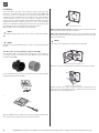
Open the RBE. Push the screwdriver into one of the 4mm openings in the
side to open the clip. Repeat this step for all four openings.
2.
Montage
RMU 40 kann nicht direkt an einer Wand montiert wer-
den, da an der Rückseite eine Anschlussklemme hervor-
ragt.
Montieren Sie RMU 40 entweder in einer leeren Geräte-
dose oder am beiliegenden Abstandsstück aus Kunststoff.
Wenn Sie den Raumfühler der RMU 40 nutzen wollen,
ist die Platzierung der Raumeinheit entscheidend. Siehe
Abschnitt "Raumtemperaturfühler".
1.
LEK
Öffnen Sie RMU 40, indem Sie einen Schraubendre-
her in einen der 4 mm breiten Spalte am Rand füh-
ren. Drücken Sie den Schraubendreher gerade hinein,
um die Klammer zu öffnen. Wiederholen Sie den
Vorgang für die drei restlichen Klemmen.
2.
LEK
Ohne Abstandsstück aus Kunststoff: Setzen Sie die
Rückabdeckung vor die Gerätedose und verschrauben
Sie sie an der Wand.
Mit Abstandsstück aus Kunststoff: Schrauben Sie das
Abstandsstück aus Kunststoff in die Wand. Befestigen
Sie anschließend die Rückabdeckung mithilfe der
beiden beiliegenden Schrauben am Abstandsstück
aus Kunststoff.
3.
LEK
Führen Sie den Anschluss gemäß Abschnitt "Elektri-
scher Anschluss" aus.
4.
LEK
Winkeln Sie die Frontabdeckung um ca. 30 ° an und
befestigen Sie die beiden Klemmen auf einer Seite.
Schließen Sie nun die Einheit und drücken Sie die
beiden Klemmen auf der anderen Seite fest.
22
DE
Without surface-mounted frame: Position the rear cover in front of the
ush-mounted box and screw it onto the wall.
With surface-mounted frame: Screw the surface-mounted frame onto
the wall. Then use the two screws supplied to x the rear cover onto the
surface-mounted frame
NOTE
Ensure that the screw heads do not touch the circuit board.
3.
Montage
RMU 40 kann nicht direkt an einer Wand montiert wer-
den, da an der Rückseite eine Anschlussklemme hervor-
ragt.
Montieren Sie RMU 40 entweder in einer leeren Geräte-
dose oder am beiliegenden Abstandsstück aus Kunststoff.
Wenn Sie den Raumfühler der RMU 40 nutzen wollen,
ist die Platzierung der Raumeinheit entscheidend. Siehe
Abschnitt "Raumtemperaturfühler".
1.
LEK
Öffnen Sie RMU 40, indem Sie einen Schraubendre-
her in einen der 4 mm breiten Spalte am Rand füh-
ren. Drücken Sie den Schraubendreher gerade hinein,
um die Klammer zu öffnen. Wiederholen Sie den
Vorgang für die drei restlichen Klemmen.
2.
LEK
Ohne Abstandsstück aus Kunststoff: Setzen Sie die
Rückabdeckung vor die Gerätedose und verschrauben
Sie sie an der Wand.
Mit Abstandsstück aus Kunststoff: Schrauben Sie das
Abstandsstück aus Kunststoff in die Wand. Befestigen
Sie anschließend die Rückabdeckung mithilfe der
beiden beiliegenden Schrauben am Abstandsstück
aus Kunststoff.
3.
LEK
Führen Sie den Anschluss gemäß Abschnitt "Elektri-
scher Anschluss" aus.
4.
LEK
Winkeln Sie die Frontabdeckung um ca. 30 ° an und
befestigen Sie die beiden Klemmen auf einer Seite.
Schließen Sie nun die Einheit und drücken Sie die
beiden Klemmen auf der anderen Seite fest.
22
DE
Make the connection as described in the “Electrical connection” section.
4.
Montage
RMU 40 kann nicht direkt an einer Wand montiert wer-
den, da an der Rückseite eine Anschlussklemme hervor-
ragt.
Montieren Sie RMU 40 entweder in einer leeren Geräte-
dose oder am beiliegenden Abstandsstück aus Kunststoff.
Wenn Sie den Raumfühler der RMU 40 nutzen wollen,
ist die Platzierung der Raumeinheit entscheidend. Siehe
Abschnitt "Raumtemperaturfühler".
1.
LEK
Öffnen Sie RMU 40, indem Sie einen Schraubendre-
her in einen der 4 mm breiten Spalte am Rand füh-
ren. Drücken Sie den Schraubendreher gerade hinein,
um die Klammer zu öffnen. Wiederholen Sie den
Vorgang für die drei restlichen Klemmen.
2.
LEK
Ohne Abstandsstück aus Kunststoff: Setzen Sie die
Rückabdeckung vor die Gerätedose und verschrauben
Sie sie an der Wand.
Mit Abstandsstück aus Kunststoff: Schrauben Sie das
Abstandsstück aus Kunststoff in die Wand. Befestigen
Sie anschließend die Rückabdeckung mithilfe der
beiden beiliegenden Schrauben am Abstandsstück
aus Kunststoff.
3.
LEK
Führen Sie den Anschluss gemäß Abschnitt "Elektri-
scher Anschluss" aus.
4.
LEK
Winkeln Sie die Frontabdeckung um ca. 30 ° an und
befestigen Sie die beiden Klemmen auf einer Seite.
Schließen Sie nun die Einheit und drücken Sie die
beiden Klemmen auf der anderen Seite fest.
22
DE
Position the front cover with an angle of around 30° and fasten the two
xing clips on one side. Now close the control unit and press the two
clips on the other side rmly into place.

583032600bUK– Translation into English of the original German operating manual – Subject to technical change without notice.
Funktion
Raumbedieneinheit
A
+12V
2
GND
1
B
RBE
LIN-Bus
RJ45
4
3
RBE
RJ45
A2
A2
Bezeichnung
Legende: DE831183
Bedienteil
1
Raumbedieneinheit
2
3
4
RBE
Raumbedieneinheit RBE
Datum
831183
Achim Pfleger 24.07.2013
- PEP 008/2013
Bl von Anz
Name
1 2 3 4 5 6 7 8 9 10 11 12 13 14 15 16
1 2 3 4 5 6 7 8 9 10 11 12 13 14 15 16
1/1
1
Datum
Bearb.
Änderung
24.07.2013
Zustand
-
Blatt-Nr.
A. Pfleger
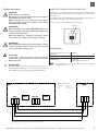
CONNECTING THE COMMUNICATIONS AND POWER SUPPLY
Communication and power supply take place via the RS485 interface
attached to the heat pump control unit. The RBE must be connected to
this interface.
Use a exible cable type (LiYY, EKKX) or equivalent. The required and at
the same time maximum cable cross-section 0.5 mm².
Connect as shown in the following terminal diagram:
Terminal
Elektrischer Anschluss
HINWEIS!
Alle elektrischen Anschlüsse müssen von einem
geprüften Elektriker ausgeführt werden.
Bei der Elektroinstallation und beim Verlegen
der Leitungen sind die geltenden Vorschriften
zu berücksichtigen.
F1145/F1245/F370/F470/F750 darf bei der Instal-
lation von RMU 40 nicht mit Spannung versorgt
werden.
Anschluss von Kommunikation und Span-
nungsversorgung
Die Klemme in RMU 40 wird mit Klemme X4:9–12 an
der Eingangskarte (AA3) in der Wärmepumpe verbunden.
Verwenden Sie Kabeltyp LiYY, EKKX oder gleichwertig.
RMU 40
+12V GND B A
$QVFKOXVVNOHPPH
F1145
F1145RMU 40
A
B
GND
+12V
8
9
10
7
11
12
13
$$;
508b )
$$;
F1245
+12V
ABGND
12
1110 13987
F1245
RMU 40
508b
)
$$;
$$;
F370/F470
+12V
ABGND
12
1110 13987
F1245
RMU 40
508b
))
$$;
$$;
F750
+12V
ABGND
12
1110 13987
F1245
RMU 40
508b
)
$$;
LEK
$$;
Mehrere RMU 40/SMS 40-Einheiten
Soll eine weitere RMU 40-Einheit bzw. SMS 40-Einheit
mit F1145/F1245/F370/F470/F750 verbunden werden,
ist diese von der Anschlussklemme in der ersten Einheit
umzusetzen. Es können maximal zwei Einheiten ange-
schlossen werden.
)))))
508b
606
508b
606
Värmepump
RMU 40
RMU 40
8
9
10
7
11
12
13
A
B
GND
+12V
A
B
GND
+12V
$$;
508b
508b
:¦UPHSXPSH
23
DE
Technical data
Surface-mounted frame made of plastic
WxHxD (mm)
85x85x35
RBE dimensions WxHxD (mm) 85x85x14
Nominal voltage 12 V DC 40 mA
(Power supply from the heat pump)
To commission or start up the RBE, follow the procedure
described on page 9.
Electrical connection
DANGER!
Risk of fatal electric shock!
All electrical connection work must be carried out
by qualied electricians only.
Before opening the unit, disconnect the system
from the power supply and prevent it from being
switched back on again!
WARNING!
Note and follow the relevant EN, VDE and/or local
safety regulations during installation and when car-
rying out electrical work.
Note and follow the technical connection condi-
tions of the responsible power supply company!
WARNING!
Only qualied personnel (trained heating or refrig-
eration engineer or electrician) may carry out work
on the unit and its components.
CAUTION!
A cable with a small cross-section reduces the approved
length of the connection cable. If the cable is too long the
RBE may not work!
ATTENTION
Electrical work on the room control unit may only be car-
ried out by the authorised service personnel or specialised
rms, which have been authorised by the manufacturer.
max. 30 m*
* The 30 m between the heat pump (WP) control unit and the RBE are only allowed if the connection cable between the WP
control unit and the master board of the WP control is ≤ 3m.
Room control unit

6 83032600bUK– Translation into English of the original German operating manual – Subject to technical change without notice.
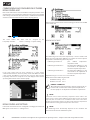
COMMISSIONING AND CONFIGURATION OF THE RBE
ROOM CONTROL UNIT
If the room control unit is connected with the heat pump control it can be
started up. The room control unit positioned in the room is now supplied
with voltage and activated. The connection is established and the blue
status bar in the bottom left-hand side of the display lights up:
The room control unit must now be assigned to the
heat pump controller: Service >> Settings >> System Setting
If the room control unit has been activated as a room station,
communication between the heat pump control and RBE starts. After
a few seconds the RBE has received all the necessary data from the
heat pump control and is ready for use. It now displays all the relevant
operating data from the connected heat pump:
ROOM CONTROL UNIT SETTINGS
If the room control unit has been congured accordingly, the menu item
RBE appears in the Service >> Settings menu:
This menu item contains all the relevant settings parameters for the RBE
room control unit:
INFLUENCING FACTOR RT
The inuencing factor RT (room temperature) is used to dene how
much the room temperature dierence is to aect the return setpoint
temperature calculated using the heating curve:
Inuencing factor RT 0% pure outdoor temperature-
dependent control
Inuencing factor RT 100% 1K temperature dierence in the
room results in 1K adjustment of
the return setpoint temperature
Inuencing factor RT 200% 1K temperature dierence in the
room results in 2K adjustment of
the return setpoint temperature
Adjustment range 0 % to 200 % in 10 % increments.
Guide values for the inuencing factor RT:
• Underoor heating 100%
• Radiators / fan coils 200%
€
ENERGY SAVING TIP
By including the room temperature, external energy inputs can
be taken into account better and the system temperature of
the heat pump can be adjusted in line with the requirements.
NOTE
If the main room is heated excessively compared to other rooms in the
home (e.g. by a stove), and the inuencing factor RT is set at an excessively
high level, this can result in loss of comfort in other rooms in the home.
Because the temperature input in the main room lowers the temperatures
and therefore the heating system output in the other rooms
.
NOTE
The inuencing factor RT basically depends on the condition and
characteristics of the heat distribution system.

783032600bUK– Translation into English of the original German operating manual – Subject to technical change without notice.
COOLING RELEASE
Here there are 2 options for releasing and activating cooling:
• Purely according to outdoor temperature
If the outdoor temperature release that has been set is exceeded over the
dened time period the heat pump switches to cooling mode.
RBE operating manual, see “Cooling”
Trained installers' operating manual, see “Cooling – Setting the
parameters”
Comfort circuit board operating manual, see “Comfort cooling –
Setting the parameters”
• According to outdoor temperature & room temperature
inuence
If the room temperature release that has been set is exceeded over
the dened time period the heat pump control checks the outdoor
temperature release. If the outdoor temperature release is also available
the heat pump switches to cooling mode.
RBE operating manual, see “Cooling”
HEAT DISTRIBUTION SYSTEM
The heat distribution system parameter limits the maximum adjustment
of the return setpoint temperature of the heat pump control:
• Underoor heating max. +/- 2K
• Radiators / fan coils max. +/- 4K
ADJUSTMENT OF THE RETURN SETPOINT TEMPERATURE
UNDER ROOM TEMPERATURE INFLUENCE
The room temperature inuence is basically calculated using the
following formula:
(t
Room setpoint
– t
Room actual
) * f
RT
= T
RL
setpoint adjustment
t
Room setpoint
= room setpoint temperature
t
Room, actual
= current room temperature
f
RT
= inuencing factor RT 0…200%
T
RL
setpoint = return setpoint temperature in the heat
pump control
NOTE
Control with room temperature inuence is compatible with heating and
cooling mode. Maximum ow and return temperature limits for heating
and cooling remain active in order to protect the components integrated
in the system.
The following shows 3 examples in which the control principle is illustrated:
Example 1:
Increasing the return setpoint temperature in heating mode:
Return setpoint temperature = 28°C
Underoor heating
Room temperature = 19°C
Room setpoint temperature = 22°C
Inuencing factor selected in the heat pump controller: 50%
(22°C - 19°C) * 50% = 1.5K
--> check < 2K --> YES --> Return setpoint adjustment --> 29.5°C
Example 2:
Lowering the return setpoint temperature in heating mode:
Return setpoint temperature = 30°C
Underoor heating
Room temperature = 22°C
Room setpoint temperature = 20°C
Inuencing factor selected in the heat pump controller: 50%
(20°C - 22°C) * 50% = - 1K
--> check < 2K --> YES --> Return setpoint adjustment --> 29°C
Example 3:
Lowering the ow temperature (mixing circuit) in cooling mode:
Flow temperature, mixing circuit, cooling = 18°C
Underoor heating
Room temperature = 24°C
Room setpoint temperature = 22°C
Inuencing factor selected in the heat pump controller: 50%
(22°C - 24°C) * 50% = - 1K
--> Check < 2K --> YES --> Cooling ow temperature adjustment
--> 17°C --> if minimum cooling ow temperature 17°C allowed
--> yes --> if not, no adjustment!

8 83032600bUK– Translation into English of the original German operating manual – Subject to technical change without notice.
Layout and handling
Programmeinstellungen
1.
Halten Sie die Zurück-Taste an RMU 40 für die Dauer
von 7 s gedrückt, um folgendes Menü aufzurufen:
"Serviceeinstellungen".
2.
Rufen Sie das Menü auf und wählen Sie das Klimati-
sierungssystem aus, mit dem RMU 40 verbunden
werden soll.
3.
Starten Sie die Wärmepumpe, wechseln Sie zu Menü
"Systemeinst." (5.2) und aktivieren Sie RMU 40 für
das Klimatisierungssystem, das per Raumeinheit ge-
steuert werden soll.
4.
Wenn die Wärmepumpe einen Raumfühler zur
Temperaturregelung nutzen soll, wird dies im folgen-
den Menü eingestellt: "Raumfühlereinstellungen"
(1.9.4). Wenn ein externer Raumfühler (BT50) instal-
liert ist, wird dieser verwendet. Andernfalls wird der
Raumfühler in RMU 40 genutzt.
HINWEIS!
Die Software in F1145/F1245/F370/F470/F750
muss Version 1199 oder höher aufweisen, damit
RMU 40 unterstützt wird.
Steuerung – Einführung
Raumeinheit
$
% & ' (
Display
Auf dem Display erscheinen Anweisungen,
Einstellungen und Betriebsinformationen.
A
Standby-Taste
Mit der Standby-Taste lässt sich RMU 40 in den
Standby-Modus versetzen. Ein Drücken der Taste
wirkt sich nicht auf den Wärmepumpenbetrieb
aus.
B
Zurück-Taste
Die Zurück-Taste wird in folgenden Fällen verwen-
det:
႑
kehrt zum vorherigen Menü zurück.
႑
macht eine noch nicht bestätigte Einstell-
ung rückgängig.
C
OK-Taste
Die OK-Taste wird in folgenden Fällen verwendet:
႑
bestätigt die Auswahl von Untermenü/Op-
tion/eingestelltem Wert.
D
Auf- und Ab-Taste
Per Auf- und Ab-Taste können Sie:
႑
navigiert in Menüs und wechselt zwischen
den Optionen.
႑
Werte erhöhen oder verringern.
E
24
DE
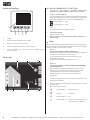
3
5
1
2
4
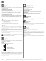
1. Display
2. Activate from standby or place in standby
3. Return or cancel from current setting
4. Conrm setting or switch to one menu level lower
5. Scroll - down/up (in the vertical menu) or left/right (in the
horizontal menu)
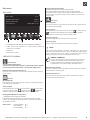
Start screen
3
5
1
2
7 46
FUNCTIONS AND INFORMATION IN THE START SCREEN:
1. DISPLAY OF THE CURRENT OUTDOOR TEMPERATURE
MEASURED AT THE OUTDOOR SENSOR OF THE HEAT PUMP
2. ENABLE / DISABLE COOLING
Here it is possible to release (enable) or block (disable) cooling for
heat pumps with passive or active cooling function. However, the
heat pump controller release criteria are not disabled by this.
= Cooling enabled = ON
= Cooling disabled = OFF
3. TIME
This is taken from the heat pump controller
4. NAVIGATION ARROW
Switch to the main menu
5. ROOM SETPOINT TEMPERATURE WITH TEMPERATURE ADJUST
MENT OPTION
NOTE
The type of temperature adjustment depends on the selected reference
variable according to room or outdoor temperature. The basic settings for
this must be made in the heat pump controller.
Option 1:
For control according to outdoor temperature
Shows the extent to which the hot water return ow temperature
is to deviate from that of the set heating curve.
Increase (lower) the value to increase or lower the room
temperature respectively.
Maximum value of the possible dierence: ± 5.0°C
Option 2:
For control according to outdoor temperature including the
room temperature
Displays which room setpoint temperature is to be reached.
Depending on the current actual value, the return setpoint
temperature in the heat pump controller is adjusted.
Change this value if you also want to change the room
temperature.
6. Current room temperature measured at the temperature sensor
of the room control unit
7. Modes of the connected heat pump and display of the current
operating mode
Status of the adjacent mode:
Raumbedieneinheit – RBE
Die neue Raumbedieneinheit RBE* von Alpha-InnoTec
ermöglicht komfortable und einfache Einsicht des
aktuellen Wärmepumpenstatus und kann durch das
ansprechende Design flexibel direkt im Wohnraum
montiert werden, Aufputz oder Unterputz.
Direkt vom Wohnraum aus können so alle für den End-
kunden wichtigsten Parameter & Betriebsdaten ab-
gelesen werden. Außerdem können von dort aus die
Einstellungen, z. B. Heizungs- oder Brauchwarmwasser-
temperatur der Wärmepumpe verändert und somit das
System optimiert werden. Außerdem ermöglicht es die
Raumbedieneinheit mit dem integrierten Temperaturfüh-
ler, die Wärme pumpen-Regelung mit Raumtemperatur-
einfluss zu betreiben. Diese Funktion ist vor allem wichtig
für Neubau/Niedrigenergie- und Passivhäuser.
Unterstützt und angezeigt werden folgende Funktionen der Wärmepumpe*:
RBE
Alpha-InnoTec – eine Marke der
ait-deutschland GmbH
Industriestraße 3
D-95359 Kasendorf
Alpha-InnoTec Österreich
ECO-WP Wärmepumpen-
handelsges. m.b.H.
Währingerstraße 26
A-1090 Wien
www.alpha-innotec.de
Tel. +49 (0) 9228 9906-0
Fax. +49 (0) 9228 9906-149
www.alpha-innotec.at
Tel.: +43 (0) 800 205 852
Fax: +43 (0) 800 205 854
PV
READY
PV
READY
Heizung Warmwasser Kühlung Lüftung Solarthermie Schwimmbad Photovoltaik
*Nur in Verbindung mit Alpha-InnoTec Wärmepumpen mit Luxtronik Regler 2.1
Anzeige der Betriebszustände
Dauerhaft an
Ordnungsgemäßer Betrieb
Blinkt
Wird ausgeführt
Dauerhaft an
?
Es besteht Anforderung, es kann noch nicht ausgeführt werden (z.B. Sperrzeit)
Dauerhaft an
Betriebsart ist aus
Continuously on =
proper operation
Raumbedieneinheit – RBE
Die neue Raumbedieneinheit RBE* von Alpha-InnoTec
ermöglicht komfortable und einfache Einsicht des
aktuellen Wärmepumpenstatus und kann durch das
ansprechende Design flexibel direkt im Wohnraum
montiert werden, Aufputz oder Unterputz.
Direkt vom Wohnraum aus können so alle für den End-
kunden wichtigsten Parameter & Betriebsdaten ab-
gelesen werden. Außerdem können von dort aus die
Einstellungen, z. B. Heizungs- oder Brauchwarmwasser-
temperatur der Wärmepumpe verändert und somit das
System optimiert werden. Außerdem ermöglicht es die
Raumbedieneinheit mit dem integrierten Temperaturfüh-
ler, die Wärme pumpen-Regelung mit Raumtemperatur-
einfluss zu betreiben. Diese Funktion ist vor allem wichtig
für Neubau/Niedrigenergie- und Passivhäuser.
Unterstützt und angezeigt werden folgende Funktionen der Wärmepumpe*:
RBE
Alpha-InnoTec – eine Marke der
ait-deutschland GmbH
Industriestraße 3
D-95359 Kasendorf
Alpha-InnoTec Österreich
ECO-WP Wärmepumpen-
handelsges. m.b.H.
Währingerstraße 26
A-1090 Wien
www.alpha-innotec.de
Tel. +49 (0) 9228 9906-0
Fax. +49 (0) 9228 9906-149
www.alpha-innotec.at
Tel.: +43 (0) 800 205 852
Fax: +43 (0) 800 205 854
PV
READY
PV
READY
Heizung Warmwasser Kühlung Lüftung Solarthermie Schwimmbad Photovoltaik
*Nur in Verbindung mit Alpha-InnoTec Wärmepumpen mit Luxtronik Regler 2.1
Anzeige der Betriebszustände
Dauerhaft an
Ordnungsgemäßer Betrieb
Blinkt
Wird ausgeführt
Dauerhaft an
?
Es besteht Anforderung, es kann noch nicht ausgeführt werden (z.B. Sperrzeit)
Dauerhaft an
Betriebsart ist aus
Flashing = in progress
Raumbedieneinheit – RBE
Die neue Raumbedieneinheit RBE* von Alpha-InnoTec
ermöglicht komfortable und einfache Einsicht des
aktuellen Wärmepumpenstatus und kann durch das
ansprechende Design flexibel direkt im Wohnraum
montiert werden, Aufputz oder Unterputz.
Direkt vom Wohnraum aus können so alle für den End-
kunden wichtigsten Parameter & Betriebsdaten ab-
gelesen werden. Außerdem können von dort aus die
Einstellungen, z. B. Heizungs- oder Brauchwarmwasser-
temperatur der Wärmepumpe verändert und somit das
System optimiert werden. Außerdem ermöglicht es die
Raumbedieneinheit mit dem integrierten Temperaturfüh-
ler, die Wärme pumpen-Regelung mit Raumtemperatur-
einfluss zu betreiben. Diese Funktion ist vor allem wichtig
für Neubau/Niedrigenergie- und Passivhäuser.
Unterstützt und angezeigt werden folgende Funktionen der Wärmepumpe*:
RBE
Alpha-InnoTec – eine Marke der
ait-deutschland GmbH
Industriestraße 3
D-95359 Kasendorf
Alpha-InnoTec Österreich
ECO-WP Wärmepumpen-
handelsges. m.b.H.
Währingerstraße 26
A-1090 Wien
www.alpha-innotec.de
Tel. +49 (0) 9228 9906-0
Fax. +49 (0) 9228 9906-149
www.alpha-innotec.at
Tel.: +43 (0) 800 205 852
Fax: +43 (0) 800 205 854
PV
READY
PV
READY
Heizung Warmwasser Kühlung Lüftung Solarthermie Schwimmbad Photovoltaik
*Nur in Verbindung mit Alpha-InnoTec Wärmepumpen mit Luxtronik Regler 2.1
Anzeige der Betriebszustände
Dauerhaft an
Ordnungsgemäßer Betrieb
Blinkt
Wird ausgeführt
Dauerhaft an
?
Es besteht Anforderung, es kann noch nicht ausgeführt werden (z.B. Sperrzeit)
Dauerhaft an
Betriebsart ist aus
Continuously on = o
Raumbedieneinheit – RBE
Die neue Raumbedieneinheit RBE* von Alpha-InnoTec
ermöglicht komfortable und einfache Einsicht des
aktuellen Wärmepumpenstatus und kann durch das
ansprechende Design flexibel direkt im Wohnraum
montiert werden, Aufputz oder Unterputz.
Direkt vom Wohnraum aus können so alle für den End-
kunden wichtigsten Parameter & Betriebsdaten ab-
gelesen werden. Außerdem können von dort aus die
Einstellungen, z. B. Heizungs- oder Brauchwarmwasser-
temperatur der Wärmepumpe verändert und somit das
System optimiert werden. Außerdem ermöglicht es die
Raumbedieneinheit mit dem integrierten Temperaturfüh-
ler, die Wärme pumpen-Regelung mit Raumtemperatur-
einfluss zu betreiben. Diese Funktion ist vor allem wichtig
für Neubau/Niedrigenergie- und Passivhäuser.
Unterstützt und angezeigt werden folgende Funktionen der Wärmepumpe*:
RBE
Alpha-InnoTec – eine Marke der
ait-deutschland GmbH
Industriestraße 3
D-95359 Kasendorf
Alpha-InnoTec Österreich
ECO-WP Wärmepumpen-
handelsges. m.b.H.
Währingerstraße 26
A-1090 Wien
www.alpha-innotec.de
Tel. +49 (0) 9228 9906-0
Fax. +49 (0) 9228 9906-149
www.alpha-innotec.at
Tel.: +43 (0) 800 205 852
Fax: +43 (0) 800 205 854
PV
READY
PV
READY
Heizung Warmwasser Kühlung Lüftung Solarthermie Schwimmbad Photovoltaik
*Nur in Verbindung mit Alpha-InnoTec Wärmepumpen mit Luxtronik Regler 2.1
Anzeige der Betriebszustände
Dauerhaft an
Ordnungsgemäßer Betrieb
Blinkt
Wird ausgeführt
Dauerhaft an
?
Es besteht Anforderung, es kann noch nicht ausgeführt werden (z.B. Sperrzeit)
Dauerhaft an
Betriebsart ist aus
Continuously on = request exists, but it cannot be
carried out yet (e.g. o time)

983032600bUK– Translation into English of the original German operating manual – Subject to technical change without notice.
Main menu
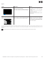
BASIC LAYOUT:
3
1
2
4
Amb. temp- -9.2°C
Targeted room temp. 22.0°C
Current room temp. 22.1°C
el. rod active at 16.03.2014 11:11
1. Information and settings in the respective submenu
2. other menu items (optional if a corresponding number of
functions are available)
3. Submenu
4. Selected menu item
CONTENTS OF THE SUBMENU:
INFORMATION
Current outdoor temperature
Current room temperature setpoint or return temperature setpoint
Current actual room temperature or actual return temperature
Electric heating element last active on
Here you can see when the electric heating element was last activated
by the control
HEATING
Operating mode
Here you can view the current type of operation and if required change
it too (Automatic, Party, O)
Timer program
Info, whether the heat pump control operated on the basis of the timer
program in daytime mode or night-time mode . Temperature
and time settings for this can be made in the heat pump control.
Heating below Ø outdoor temperature
= heating limit in the heat pump controller
If the temperature falls below the set temperature, the heat pump
switches to heating mode. This temperature is primarily dependent on
the building standard.
Guide values: Existing building: 15°C
New building: 12°C
Passive building: 10°C
Average outdoor temperature
= Average temperature in the heat pump controller
The average outdoor temperature is made up of the outdoor
temperature curve over the past 24 hours and forms the reference
variable for the heat pump control, in order to active / deactivate the
heating mode
HOT WATER
Operating mode
Here you can view the current type of operation and if required change
it too (Automatic, Party, O)
Timer program
Info, whether the heat pump control can operate or cannot operate
on the basis of the o time program. Temperature and time
settings for this can be made in the heat pump control.
Hot water, setpoint
Required temperature for hot water in the storage tank
Hot water, actual
Current temperature of the hot water in the storage tank
NOTE
Unnecessarily high domestic hot water temperatures in the storage
tank reduce the system's eciency due to the high ow temperatures,
increase stoppage losses in the storage tank and therefore increase
running costs. Specic national requirements must be met
€
ENERGY SAVING TIP
Use the extra hot water function to temporarily increase the
hot water temperatures and therefore the tap output tem-
perature. After the timer setting has expired the hot water
temperature is reset automatically to the default value.
Extra hot water setpoint
Here you can dene a temporary higher hot water temperature, which is
maintained for a settable period.
Extra hot water period
After this time has expired the heat pump is controlled once again
according to the default setpoint

10 83032600bUK– Translation into English of the original German operating manual – Subject to technical change without notice.
SOLAR THERMAL ENERGY
Solar collector, actual
Current solar collector temperature
Solar tank, actual
Current solar tank temperature
Solar collector, max
The maximum solar collector temperature reached on this day
Solar tank, max
The maximum solar tank temperature reached on this day
SWIMMING POOL
Operating mode
Here you can view the current type of operation and if required change
it too (Automatic, Party, Holidays, O)
PHOTOVOLTAICS
Operating mode
Here you can view the current type of operation and if required change
it too (Automatic, Party, Holidays, O)
SETTINGS
Software version
Current version of the room control unit software.
Language
When it is started up for the rst time the room control unit is set to the
language set in the heat pump control. This language can be changed
manually if necessary and can therefore dier from the language in the
heat pump controller.
Room sensor calibration
This function can be used to calibrate the room sensor integrated in the
RBE.
COOLING
Operating mode
Here you can view the current type of operation and if required change
it too (Automatic, O)
Cooling from outdoor temperature
= AT release in the heat pump controller
If the outside temperature that has been set is exceeded, the heat pump
switches to cooling mode. This temperature is primarily dependent on
the building standard and the demand for cooling in the building
Cooling from room temperature
= RT exceeded in heat pump controller
If the set room temperature is exceeded there is a demand for cooling.
The cooling is only started if the outdoor temperature release is also
available
NOTE
Cooling mode can be released optionally according to the
• Outdoor temperature
• Outdoor & room temperature
. This basic setting must be made in the heat pump control
NOTE
Cooling is activated if the corresponding release temperature(s) for
the time period set in the heat pump controller (factory setting: 12h)
has(have) been exceeded.
Cooling is deactivated if the corresponding outdoor temperature release
for the time period set in the heat pump controller (factory setting: 12h)
has been exceeded.
The time period is skipped if the temperature is already 5 K above or
below the release temperature
For detailed information on this, please refer to the operating
manual of the heat pump controller.
VENTILATION
Operating mode
Here you can view the current type of operation and if required change
it too (Automatic, Party, O)
Fan level
Info on which of the 4 fan levels is active:
O
Humidity control
Reduced operation
Nominal ventilation/Party
Intensive ventilation
Intensive ventilation period
Here you can run the ventilation in maximum mode for a settable period
and therefore achieve the highest possible air exchange. After this time
has expired the heat pump is controlled once again according to the
operating modes program

1183032600bUK– Translation into English of the original German operating manual – Subject to technical change without notice.
FAULTS
Display Description Remedy
Black display and status bar for connection
set up is illuminated permanently
Communication cannot be set up between the heat
pump control unit and the RBE.
This can be caused by the software (settings in the
heat pump controller) or by the hardware (wiring)
Check whether:
• the RBE has been activated under the
System Settings in the heat pump
controller
• the RBE has been wired correctly with the
heat pump control unit
• the heat pump controller software is at least
Version x.68
The operating modes displayed in the RBE
do not correspond with those in the heat
pump
The RBE mirrors the operating modes from the heat
pump control. If a mode is not displayed in the RBE it
is also not displayed in the heat pump controller.
Activate the required operating modes
under the System Settings in the heat pump
controller. As these are basic settings for
operation of the heat pump system you must
get a competent person (installer) to make
the necessary changes.
If a non-self-resetting (hard) fault exists in the heat pump controller, this is displayed in the home by the room control unit, including the error code.
If the heat pump controller is congured in such a way that the second heat generator (ZWE) is activated automatically during a fault, this is also
displayed.
For further information on the displayed error code, please refer to the operating manual of the heat pump controller.

Made by ait-deutschland GmbH
-
 1
1
-
 2
2
-
 3
3
-
 4
4
-
 5
5
-
 6
6
-
 7
7
-
 8
8
-
 9
9
-
 10
10
-
 11
11
-
 12
12


Alpha innotec RBE Owner's manual
- Category
- Heat pumps
- Type
- Owner's manual
Ask a question and I''ll find the answer in the document
Finding information in a document is now easier with AI
in other languages
Related papers
-
Alpha innotec alpha home Owner's manual
-
Alpha innotec Lux 20 21 Teil 1 Owner's manual
-
-
-
-
-
-
-
-
Other documents
-
Quantum Scalar 24 Installation guide
-
Sealite SL-RMU Quick start guide
-
Nibe F370 Quick Start User Manual
-
Nibe F1355 Series Operating instructions
-
-
Dimplex BWP 30 HLW Operating instructions
-
Nice F470 User manual
-
-
 LAMBERTI ELEKTRONIK LATHERM SOL BASIS Operating instructions
-
Nibe F470 Installer Manual
