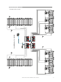
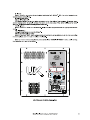
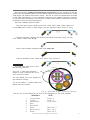
DAS UX-218A is a high-output ultra-low frequency loudspeaker enclosure. With a frequency response of 29 Hz to 150 Hz, it is ideal for use in a variety of applications, including live sound reinforcement, club installations, and home theaters. The UX-218A is powered by a 1,200-watt amplifier and features a 18-inch woofer with a 4-inch voice coil. It also has a built-in DSP with presets for a variety of applications. The UX-218A is a rugged and reliable loudspeaker enclosure that is built to withstand the rigors of professional use.
DAS UX-218A is a high-output ultra-low frequency loudspeaker enclosure. With a frequency response of 29 Hz to 150 Hz, it is ideal for use in a variety of applications, including live sound reinforcement, club installations, and home theaters. The UX-218A is powered by a 1,200-watt amplifier and features a 18-inch woofer with a 4-inch voice coil. It also has a built-in DSP with presets for a variety of applications. The UX-218A is a rugged and reliable loudspeaker enclosure that is built to withstand the rigors of professional use.


-
 1
1
-
 2
2
-
 3
3
-
 4
4
-
 5
5
-
 6
6
-
 7
7
-
 8
8
-
 9
9
-
 10
10
-
 11
11
-
 12
12
-
 13
13
-
 14
14
-
 15
15
-
 16
16
-
 17
17
-
 18
18
-
 19
19
-
 20
20
-
 21
21
-
 22
22
-
 23
23
-
 24
24
-
 25
25
-
 26
26
-
 27
27
-
 28
28
-
 29
29
-
 30
30
-
 31
31
-
 32
32


DAS UX-218A User manual
- Category
- Speaker sets
- Type
- User manual
DAS UX-218A is a high-output ultra-low frequency loudspeaker enclosure. With a frequency response of 29 Hz to 150 Hz, it is ideal for use in a variety of applications, including live sound reinforcement, club installations, and home theaters. The UX-218A is powered by a 1,200-watt amplifier and features a 18-inch woofer with a 4-inch voice coil. It also has a built-in DSP with presets for a variety of applications. The UX-218A is a rugged and reliable loudspeaker enclosure that is built to withstand the rigors of professional use.
Ask a question and I''ll find the answer in the document
Finding information in a document is now easier with AI
in other languages
- español: DAS UX-218A Manual de usuario
Related papers
-
DAS AERO-50 User manual
-
DAS LX-218CA-R-NET User manual
-
-
-
-
D.A.S. SX-218 User manual
-
-
DAS Audio VANTEC-20A User manual
-
-
Other documents
-
Qtx QT18S User manual
-
 PK Sound KLARITY 12 Owner's manual
-
Tannoy VXNET 12-WH Quick start guide
-
SBS TEAEROLGLFIK Datasheet
-
 MAG Fly Sub 18 User manual
-
Bose F1 Model 812 Flexible Array loudspeaker Owner's manual
-
Martin M-Flex S User manual
-
Mach M-Flex S User manual
-
 Pass Labs 1INT-30A User manual
-
QSC HPR122i User manual


