Page is loading ...

WIRELESS PASSIVE
INFRARED DETECTOR WITH
PET IMMUNITY
«Pyrone-5RK»
1 General Information
1.1 Wireless passive infrared detector «Pyrone-5RK» (hereinafter,
the Detector) is intended for detecting intrusion into a closed protected
space, generating an alarm message and it’s transmission via a
two-way wireless channel within the 433.05 — 434.79 MHz frequency
range according to «Rielta-Contact-R» wireless two-way data exchange
protocol.
The Detector is intended to operate as a component of a system
that is operated by any control panel (hereinafter, CP) supporting
«Rielta-Contact-R» wireless two-way data exchange protocol.
1.2 The Detector powered by one power supply lithium CR123A.
1.3 The Detector comprises two-color (green and red) LED indicator,
which is intended for the Detector operability monitoring. The possibility
of indicator disabling is provided.
1.6 The Detector is equipped with a jumper for sensitivity adjustment
and «RESET» contacts for the Detector changeover to «Binding» mode.
1.7 The Detector ensures generation and transmission via radio
communication the following messages:
- normal state message;
- alarm message;
- tamper message;
- power-supply low-battery message;
- «Binding» mode operation indication;
- «Identification» mode indication;
- communication quality indication.
1.8 Radio communication is initiated by the Detectors at 10, 15, 30 sec
,
1, 5, 10 min intervals assigned in the process of the Detector
adjustment. Alarm and tamper messages are transmitted immediately.
1.9 The Detectors are designed to operate continuously, around
the clock.
1.10 The Detectors have immunity to electromagnetic interference.
2 Features of the Detector
- Dual-element pyrodetector.
- Distortions prevention in the detection zone by means of spherical
lens.
- Pet immunity.
- Protection against ingress of insects to the pyrodetector.
- Pet immunity adjustment.
- Automatic switching to a backup operating frequency in case of
an imperfect interference situation on the main one.
3 Field of Application
The Detector can be installed in apartments, as well as in shops,
offices, museums and industrial facilities. The Detector may be installed
in premises, that are inhabited by pets weighing up to 40 kg (20 kg).
4 Specifications
Table 1
Parameter Value
Detection zone size, m 10 x 10
Detection zones 8 long-range zones,
4 short-range zones
Maximum detection range, m 10
Detected speed range, m/sec 0.3 … 3
Operating temperature, °С
from minus 20 ... +50
Permissible relative humidity at +25 °С, % 98
Ambient class
Boreal climate
IP Rating IP41
Dimensions, not more, mm 105 х 75 х 56
Weight, not more, kg 0.1
Battery life (under normal climatic conditions
and with a radio exchange period equal to at
least 30 sec), years
5
Average service life, years 8
5 Scope of Delivery
5.1 Each «Pyrone-5RK» package contains the items listed in the
Table 2.
Table 2
Name QNT
Wireless passive infrared detector «Pyrone-5RK»
Swivel bracket
Lithium power supply battery СR123A
Wireless passive infrared detector «Pyrone-5RK». Installation Guide
1 pc.
*
1 pc.
1 copy
* – supplied optionally
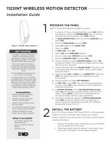
010 m
Side View
Top View
2.3 m
0
90о
10 m
Figure 1
7 Binding with the CP
The Binding procedure is intended for logging of the Detector in the
CP and transmission of service information to it.
7.1 Prepare the CP for the Detector logging in accordance to the
CP manual.
7.2 Install the PCB into the Detector case, and then install the
СR123А power-supply battery.
7.3 Blinking of the LED indicator green displays the Detector
readiness for the binding procedure. In case the LED indicator does
not blink, close the «Reset» contacts for a short period.
7.4 After a successful binding with the CP, the LED indicator lights
red for 2 sec.
7.5 The «Binding» procedure is limited to 100 sec. After it expires,
the Detector switches to the sleep mode. To resume the «Binding»
mode, the «Reset» contacts should be temporary closed.
8 LED Indication
Table 3
Detector State
LED Indication
LED status Operation
Mode
«Binding» LED indicator blinks green
«Alarm»*
LED indicator lights red for at
least 0.5 sec
if indication is
enabled
«Identification»
LED indicator blinks red and
green alternately at 1 Hz
frequency
by a command
from the CP
«Connection quality» See «Communication Quality Appraising»
Binding procedure
completed
LED indicator lights red
for 2 sec
*) — Alarm indication is deactivated 15 min after the Detector cover is closed
and activated after it has been opened or by a command from the CP
9 Choosing an Installation Place for the Detector
The Detector must be located in the radio-coverage zone of it’s
CP. Therefore, it is advisable to appraise quality of communication
beforehand. The procedure of communication quality appraising is
described in the chapter «Communication Quality Appraising».
When choosing the Detector installation place, it is advisable
to take note of the fact that the detection zone may be limited by
non-transparent objects (curtains, houseplants, cabinets, bookcases,
etc.), as well as glass and mesh partitions. There must be no windows,
air conditioners, space heaters or heating radiators in the Detector
visibility zone. The presence of furniture items on which an animal may
climb in the detection zone may cause a false alarm.
Recommended installation height — 2.3 m from the floor.
The Detector should be installed at least 0.5 m distance from
electric cables.
Installation Guide

«RIELTA» JSC, www.rielta.com
Chapaeva Str. 17, Saint Petersburg, Russia, 197101, [email protected]
Tel./fax: +7 (812) 233-0302, 703-1360
Technical support, tel.: +7 (812) 233-29-53, 703-13-57, [email protected]
Rev. 1 of 27.06.17
№ 0 0 3 3 4
Made in Russia
10 Communication Quality Appraising
Before installing the Detector to it’s place of operation, it is advisable
to appraise the CP communication quality as follows.
10.1 Prepare the Detector for operation and put it on it’s location
place with a closed cover.
10.2 Open the Detector case, whereupon the Detector will indicate
the quality of CP communication.
Table 4
LED Indication Communication
Quality Appraisal
Recommendations
LED indicator blinks green
three times Excellent Install the
Detector at this
place
LED indicator blinks green
two times Good
LED indicator blinks green
one time
Communication
established Choose another
place of
installation or use
a repeater*)
LED indicator blinks red four
times No communication
*) — «Ladoga BRSS-RK-RTR» or «Ladoga BRSS-RK-RTR», ver.1
11 Installing the Detector
Before installing the Detector, remove it’s cover and the PCB. For
this purpose:
- remove the cover of the Detector;
- loosen the screw fastening the PCB, move it upwards and remove
it from the Detector base;
- drill the holes (Figure 2) in the base of the Detector case. They
will be used for fastening the Detector;
- choose the installation place, mark out and drill the installation
places in the wall with regard for the position of the holes on the
Detector base;
- fasten the Detector base in the chosen place;
- reinstall the PCB;
- put on the cover, screw in the retainer screw 2.9x6.5 DIN7981F
(supplied).
Note — To exclude false alarms in the pet immunity mode, the
Detector should be installed vertically.
13 Detector Behavior
13.1 The Detector is powered on and off by installation and removal
of the main power-supply battery.
13.2 After loss of communication with the CP, the Detector will
continue to search for the CP. In case the CP is disabled for a long
time, it is recommended to power off the Detector (see Cl. 13.1).
13.3 It must be taken into account, that in case of the Detector
operation within +5 °C to minus 20 °C temperature range, the battery
life may be less than 5 years.
ATTENTION! The Detector must be checked at least annually in
order to test it’s performance.
14 Storage and Transportation
14.1 The Detectors in their original packing may be shipped by any
transport means in covered vehicles (in railway, cars, trucks, sealed
heated compartments of aircraft, ship cargo holds, etc). The Detector
is resistant to:
а) transport jolting with the acceleration 30 m/sec2 with impact
frequency from 10 to 120 impacts/sec or 15000 impacts with the
same acceleration;
b) the ambient temperature minus 50 … +50 °С;
c) relative air humidity (95 ± 3) % at the ambient temperature +35 °С.
14.2 After transportation under the conditions different to exploitation
conditions the Detector shall be ready to operate after a maximum
of six hours.
14.3 The storage room shall be free from current-conducting
dust, acid vapors, alkali and gases that cause corrosion and destroy
insulation.
15 Manufacturer’s Guarantees
15.1 The Manufacturer guarantees conformity of the Detector to
it’s Technical Specifications if conditions of transportation, storage,
assembling and operation are observed. The guaranteed storage
period is 63 months since the date of manufacturing the Detector.
15.2 The guaranteed period of operation is 60 months since the date
of commissioning within the storage period guaranteed.
15.3 The Detectors that are found to non-conforming to their
Technical Requirements shall be repaired by the Manufacturer,
provided that the installation and operation rules have been complied
with.
Note — Warranty obligations are not applied to the power-supply
battery.
16 Acceptance and Packing Certificate
Wireless passive infrared detector «Pyrone-5RK» manufactured in
accordance with current technical documentation is classified as fit
for operation and is packed by «RIELTA» JSC.
Packing date _______________________________
month, year
Holes for the wall
installation
Holes for corner
installation
PCB clip
Figure 2 – The Detector base
12 Functional Testing
In presence of the pets weighing up to 40 kg in the room, remove
the «10 kg» jumper, in presence of the pets weighting less than
10 kg in the room, install the «10 kg» jumper.
It is advisable to remove the «10 kg» jumper in the premises with a
high interference level.
Start walking across the detection zone. After 3 — 4 steps across
the detection zone, the Detector should display the detection by the
LED indicator red blink. Wait for 10 sec and continue walking across
the detection zone. There must be no indication in absence of moving
objects in the room.
/