Dayton Audio CX150-8 User manual

Type
User manual

Dayton Audio CX150-8 is a 5-1/4" coaxial driver with a 1" silk dome tweeter, capable of handling up to 100 watts RMS. Its frequency response ranges from 55Hz to 20kHz, with a sensitivity of 87dB. It features a heavy-duty stamped steel basket, a treated paper cone, and a butyl rubber surround for improved durability and sound quality. The CX150-8 is ideal for use in bookshelf speakers, home theater systems, and car audio applications.

Dayton Audio CX150-8 is a 5-1/4" coaxial driver with a 1" silk dome tweeter, capable of handling up to 100 watts RMS. Its frequency response ranges from 55Hz to 20kHz, with a sensitivity of 87dB. It features a heavy-duty stamped steel basket, a treated paper cone, and a butyl rubber surround for improved durability and sound quality. The CX150-8 is ideal for use in bookshelf speakers, home theater systems, and car audio applications.

Orian 3-Way High Output Speaker Kit Pair
Thank you for purchasing the Orian 3-way High Output speaker kit. The enclosure for this speaker
kit was precision cut using CNC machinery for a tight fit to make it easy to finish. With a little time
and patience, your finished product will provide years of enjoyment. Please follow these instructions
for the best possible results.
Note: The Orian uses an open back midrange to create a wide soundstage and more immersive sound.
However, in certain situations a damped rear chamber might be preferred to minimize reflections that
could negatively affect the on-axis response. This kit contains everything you need for open back or
damped rear chamber operation, we recommend you try both configurations to decide which arrangement
you prefer. See Open Back or Damped Rear Chamber on page 19 for suggestions.
Suggested tools and consumables:
Drill Rag or paper towels
Screwdriver Solder
Wood clamps (you can never have too many of these) Soldering iron
Sanding block and/or electric finishing sander Hot glue gun
Wood glue Polyurethane glue (Gorilla Glue)
Wire stripper/crimper Wrench/pliers
Package contents:
First, empty the contents of the package and review parts to ensure everything has been included and
is in good condition. If any parts are missing or damaged please contact our customer service
department at 1-800-338-0531.
Note: Crossover components, binding posts, or terminals may be substituted with parts of equal or
higher quality depending on stock.
Main Components:
A) 2 x Dayton Audio CX150-8 5-1/4" Coaxial Driver with 1" Silk Dome Tweeter
B) 2 x Dayton Audio DCS205-4 8" Classic Subwoofer 4 Ohm
Crossover Components:
C) 2 x DMPC-1.5 1.5uF 250V Polypropylene Capacitor – component C1
D) 2 x DMPC-12 12uF 250V Polypropylene Capacitor – component C2
E) 2 x DMPC-18 18uF 250V Polypropylene Capacitor – component C3
F) 2 x DMPC-27 27uF 250V Polypropylene Capacitor – component C4
G) 2 x DFFC-0.47 0.47uF 400V By-Pass Capacitor – component C5
H) 2 x DMPC-2.7 2.7uF 250V Polypropylene Capacitor – component C6
I) 2 x 125uF 100V Non-Polarized Capacitor – component C7
J) 2 x AC20-50 0.50mH 20 AWG Air Core Inductor Coil – component L1
K) 4 x IC183 3.0mH 18 AWG Laminated Iron Core Inductor – component L2 and L4
L) 2 x AC201-5 1.5mH 20 AWG Air Core Inductor Coil – component L3
M) 6 x DPR20-30.0 30 Ohm 20 Watt Precision Bifilar Resistor – component R1, R3, and R4
N) 2 x DPR20-40.0 40 Ohm 20 Watt Precision Bifilar Resistor – component R2
O) 2 x Orian (CX 3-way) Crossover Printed Circuit Board
Enclosure Components:
P) 2 x Top Panel
Q) 2 x Inner Bottom Panel
R) 4 x Inner Side
S) 4 x Side Panel
T) 2 x Back Panel
U) 2 x Bottom Panel
V) 2 x Front Baffle
Wire, Hardware, and Other Components:
W) 6 x Dayton Audio BPA-38NI HD Binding Post Pair Nickel
X) 2 x Port Tube 2-1/2" ID x 8-1/2" L Flared
Y) 2 x Sonic Barrier 1/2" Acoustic Foam w/PSA 18" x 24"
Z) 2 x Acousta-Stuf Polyfill 1 lb. Bag
AA) 5 x 0.205" (16-14) Female Disconnect
BB) 5 x 0.110" (16-14) Female Disconnect
CC) 1 x 16 AWG 2-conductor Power Speaker Wire 1 ft. (Red/Black) 20 feet
DD) 25 x #6 x 3/4" Pan Head Deep Thread Black Screws
EE) 25 x #8 x 3/4" Pan Head Deep Thread Black Screws
FF) 1 yard Speaker Grill Cloth Black Yard 70" Wide
GG) 20 x Cable Ties 11" Black
Enclosure Assembly:
Note: The Inner Bottom Panel (Q) will need to have two pairs of BPA-38NI HD Binding Posts
(W) installed to allow a simple connection between the crossover board and the midrange/tweeter
driver. We recommend that you install these before assembling the enclosure. Refer to steps 3 and 4
below.
1) First, before gluing anything, do a dry fit of the enclosure to familiarize yourself with the
parts and assembly. This will also give you a chance to ensure that all pieces have been cut properly.
2) Next, set the enclosure parts out on a flat level surface and ensure that all pieces are free of
dust and debris.
3) Before assembly, mark out the location for two sets of BPA-38NI HD Binding Post Pairs (W) on
the Inner Bottom Panel (Q). The binding posts can be installed anywhere on the panel; however, we
recommend that they are installed at least 3" from the front baffle to make sure they do not interfere with
installation of the midrange/tweeter driver. Below is one possible option.
4) Drill the holes for the binding posts with a 1/4" drill bit. Remove all solder lugs, nuts, and
washers from two sets of BPA-38NI HD Binding Post Pairs (W). Place the binding post into the
rabbeted side of the panel making sure the bare wire holes in the binding posts are pointing in the
direction you desire. Tap the binding posts into position with a mallet or hammer until fully seated
(use a scrap wood block to protect the finish if using a hammer). Secure the binding posts with one
nut each and tighten with a 10 mm nut driver or socket.
5) Start with the back panel (T) lying flat with the dadoed side up, as shown.
6) Apply a small bead of glue to the inside of the rabbeted edges of all joining surfaces of the
back panel (T) and top panel (P). Then set in place applying enough pressure to ensure glue is
spread through each joint (some glue squeeze-out can be expected).
7) Apply a small bead of glue to the inside of the dadoed edges of all joining surfaces of the
inner sides (R) and the back and top panels. Then set in place applying enough pressure to ensure
glue is spread through each joint (some glue squeeze-out can be expected).
8) Apply a small bead of glue to the inside of the edges of all joining surfaces of the inner bottom
panel (Q) and the back/inner side panels. Then set in place applying enough pressure to ensure glue is
spread through each joint (some glue squeeze-out can be expected).
9) Apply a small bead of glue to the inside of the edges of all joining surfaces of one Side
panel (S) and the back/top panels. Then set in place applying enough pressure to ensure glue is
spread through each joint (some glue squeeze-out can be expected).
10) Apply a small bead of glue to the inside of the edges of all joining surfaces of the Bottom Panel
(U) and the back/side panels. Then set in place applying enough pressure to ensure glue is spread through
each joint (some glue squeeze-out can be expected).
11) Apply a small bead of glue to the inside of the edges of all joining surfaces of the other Side panel
(S) and the back/top/bottom panels. Then set in place applying enough pressure to ensure glue is spread
through each joint (some glue squeeze-out can be expected).
12) Apply a small bead of glue to the inside of the edges of all joining surfaces of the Front Baffle (V)
and the back/top/bottom panels. Then set in place applying enough pressure to ensure glue is spread
through each joint (some glue squeeze-out can be expected).
12) Make sure that all edges are flush and securely apply clamps from side to side, top to bottom, and
front to back. Apply ample pressure to ensure glue is spread evenly through each joint (some glue
squeeze-out can be expected). Visually inspect all seams to make sure they are all closed tightly, you may
need to relocate clamps (or add more clamps) to get a perfect fit.
13) Wipe away any glue squeeze-out on the outside of the enclosure with a damp rag or paper towel
(excess glue on the inside is fine). Allow to dry according to the glue manufacturer's recommendations
and remove clamps.
14) Finally, fill any open seams with wood filler or a mixture of sawdust and wood glue. Then sand all
surfaces and seams until smooth. Finish enclosure to your liking. See our web page for ideas and
examples.
Crossover assembly:
15) Begin by preparing the input, woofer, midrange, and tweeter wires. Cut one 12" piece of 16
AWG 2-conductor Wire Red/Black (CC) and label this wire "in". Then cut three more 16" pieces of
16 AWG 2-conductor Wire Red/Black and label these "woofer", "midrange", and "tweeter".
16) Strip approximately 1/2" of insulation from one end of the 12" "input" wire and make sure
the strands are tightly twisted together. Using a soldering iron apply heat to the stripped ends and tin
the bare copper as shown below.
Note: When tinning the ends only apply gentle pressure to the wire to prevent flattening the twisted
strands. You want the twisted strands to remain round. Also, use just enough solder to flow into the
strands holding them together, try to avoid big "blobs" of solder.
17) Remove the solder ring terminals from each of the BPA-38NI HD Binding Posts (W). Strip
approximately 3/4" of insulation from the other end of the 12” "input" wire and make sure the strands are
tightly twisted together. Insert the stripped ends through the small hole in two of the solder ring terminals
and fold the wire tightly to secure it to the terminal. Using a soldering iron, apply heat to the terminals and
solder the tire and terminal together. See images below.
Note: Make sure the solder flows onto both the wire and the terminal to avoid forming a "blob" on the
surface (cold joint).
Wire wrapped through terminals Wires soldered to terminals
18) Repeat steps # 16 and # 17 for the 16" wires labeled "midrange" and "tweeter".
19) Repeat step # 16 for the 16" wire labeled "woofer". Only tin one end of the "woofer" wire.
Then strip approximately 3/4" of insulation from the other end (this end should stay bare copper).
20) Prepare the crossover components as follows for easy installation onto the Orian (CX 3-way)
Crossover Printed Circuit Board:
Capacitors: Straighten out the leads and then bend at a 90° angle about 1/8" from the
capacitor.
Inductors: Straighten the leads and be sure that all enamel/insulation is removed where
the leads penetrate the crossover board. Enamel can be removed by scraping
with a razor or fine grit sandpaper.
Resistors: Straighten leads so they are pointed straight down from the body of the
resistor.
21) The Orian (CX 3-way) Crossover Printed Circuit Board (O) is labeled to make it easy to
locate and install the corresponding components and cables. Working from one side of the board to the
other, insert the leads (or wires) through the corresponding holes in the crossover board and solder into
place.
Tips: 1) Elevate the board a couple inches so you will not have to deal with trimming the leads until
the crossover is complete.
2) Apply a bed of glue beneath each component before placing them on the board to eliminate
the possibility of rattles or buzzing from the crossover.
3) Notches are cut beside each inductor so you can zip tie them into place to help support their
weight and secure them to the crossover board.
4) Tin the tip of your soldering iron with a bit of solder before each connection to prep the joint
and optimize heat transfer.
5) When soldering components to the board, use the side of the soldering iron tip to apply heat to
both the solder pad and lead/wire at the same time. This will help ensure that the solder adheres
properly.
6) If you have difficulty inserting the tinned speaker wires into their corresponding holes, apply
heat to the wire while inserting it into the board.
7) Clean the tip of your soldering iron often with a wet sponge or brass sponge to remove
oxidation. A clean and shiny tip ensures optimal heat transfer for easy soldering.
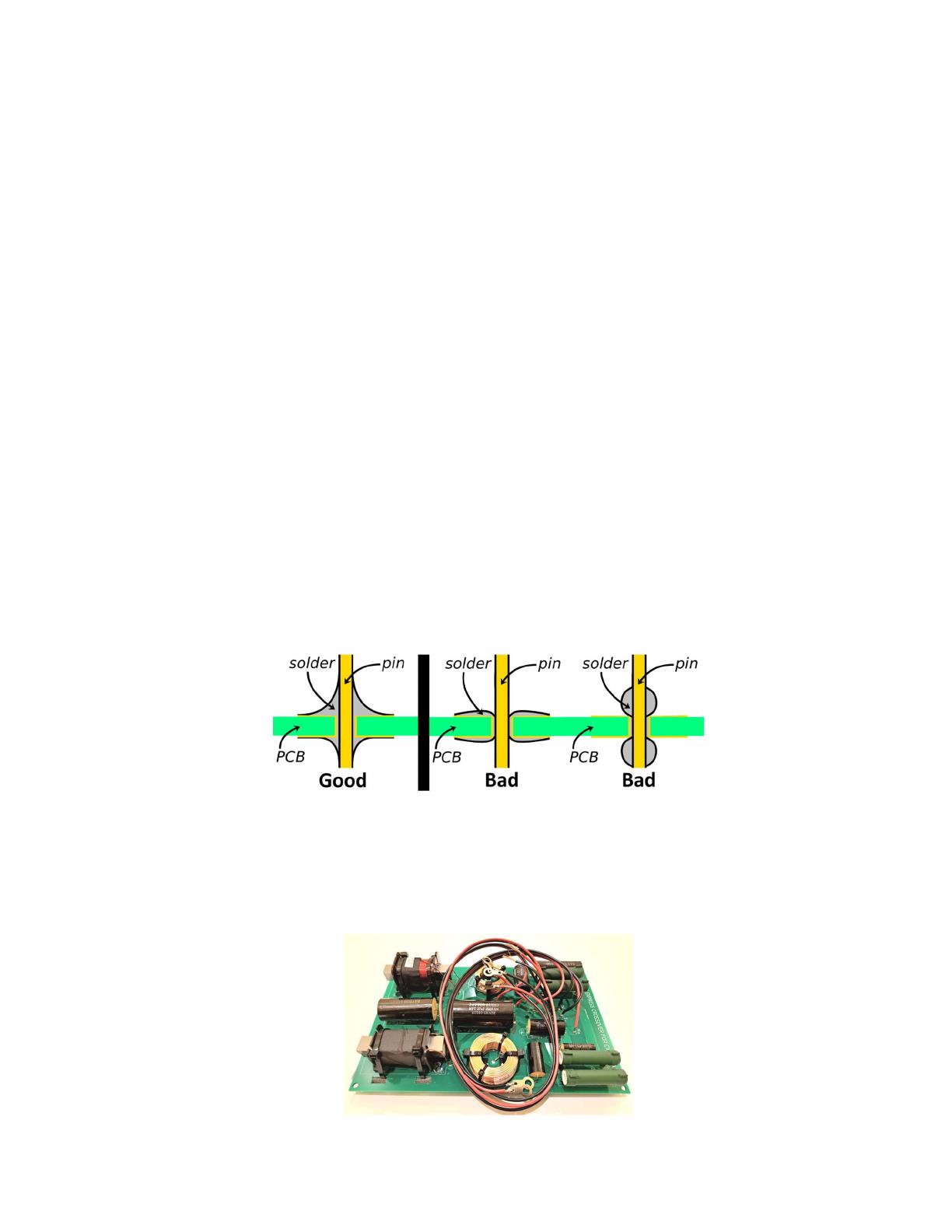
22) Carefully inspect each solder point to ensure that the solder has flowed onto the lead/wires and the
solder pads. Each solder pad is plated through-hole (PTH) type, so make sure that you inspect both the
front and back sides of the board. Each connection on the front and back of the board should have solder
covering each pad and flowing up the lead/wire. Reheat and correct any bad solder joints.
23) Trim all excess leads and wire from the back side of the crossover board using flush cutters
(preferred) or wire cutters.
24) Secure the inductors in place by looping two Cable Ties 11" Black (GG) through the holes
provided near each inductor. Tighten cable ties securely and trim off excess.
Final Assembly:
Note: We recommend that you temporarily wire everything up at this point to ensure all parts
(crossovers and drivers) are performing properly.
25) Begin final assembly by marking out the location for the BPA-38NI HD Binding Post Pair
(W) on the back of the enclosure (3/4" on center is the standard spacing if you are using dual banana
plugs). Drill a 1/4" hole for each binding post then place the binding post into position making sure
the bare wire holes in the binding posts are pointing in the direction you desire (refer to step # 4).
Tap each post into location using a mallet or hammer until fully seated (use a scrap wood block to
protect the finish if using a hammer). Secure the binding posts with one nut each and tighten with a
10 mm nut driver or socket.
Tip: There is just enough room to install the binding posts under the port opening, however the
space under the port will be limited once port is installed. Anywhere on the back panel is acceptable.
26) Lay the Sonic Barrier 1/2" Acoustic Foam w/PSA 18" x 24" (Y) on a flat, level surface.
Layout the two sheets as shown below. Cut the sheets with a sharp knife or scissors.
Note: Reserve the 1" strips cut from the edge of sheets, these will be used later.
Sheet 1 Sheet 2
27) Line the top, bottom, and sides of the midrange chamber with the pieces cut on step # 26.
Begin by marking out the locations of the binding posts in the midrange chamber in the Midrange
Bottom panel and cut a hole to allow access to the binding posts. Remove the backing from the
Midrange Bottom panel and carefully insert through the driver cutout. Carefully set the panel into
place and press firmly to adhere to the enclosure. Repeat for the Midrange top panel then the
Midrange Side panels.
Note: Install the top and bottom panels first, then the sides. Also, use care while inserting the panels
through the driver cutout. Roll the panels so the adhesive is on the outside of the curve in order to
get them to fit. The adhesive is very aggressive, do not allow it to stick to itself.
28) Remove the backing from the Woofer Side panels of Sonic Barrier and insert through the
woofer hole and adhere to the sides of the woofer enclosure. You will want to install these as low as
possible, touching the bottom of the enclosure.
29) Cut the excess Sonic Barrier that was set aside from step # 26 into five pieces about 2" - 3" long.
Peel off the backing and adhere the strips to the back side of the crossover board near the screw holes as
show below. These pieces are only there to act as a standoff for the crossover board to keep it from
vibrating and buzzing against the bottom of the enclosure.
30) Insert the crossover board through the woofer cutout and place it on the bottom of the enclosure
near the center. Place five #6 x 3/4" Pan Head Deep Thread Black Screws (DD) through the five
predrilled screw holes in the crossover board (one in each corner, and one near the "T +" connection).
Tighten screws just until the Sonic Barrier standoffs are compressed to about 1/4" – 1/8". Use care when
tightening the screws to avoid cracking the crossover board.
31) Place the port through the back panel of the enclosure. Cover the flared opening of the port with
a flat piece of wood. Then tap the port into place with a hammer or mallet until it is fully seated into the
enclosure.
32) Run the Input, Midrange, and Tweeter wires to their corresponding binding posts. For each
binding post add a lock washer, solder ring terminal, lock washer, and then nut. Be sure to observe
polarity when making these connections. Tighten each nut with a 10 mm socket. Then use some of the
excess Sonic Barrier strips to secure and cushion the wires against the port or wall to prevent buzzing.
33) Insert the bare copper ends of the "woofer" wire through the corresponding holes in the binding
posts on the Dayton Audio DCS205-4 8" Classic Subwoofer (B). Carefully set the woofer into its
opening. Use eight #8 x 3/4" Pan Head Deep Thread Screws (EE) to secure the woofer into place (a
power drill is not recommended).
34) Cut two pieces of 16 AWG 2-conductor Wire Red/Black (CC) that will reach from the binding
posts in the midrange chamber and extend about 4" past the front baffle. If you installed the binding
posts as shown in step # 3, then the wires should be about 8" long. Label one wire "midrange" and the
other wire "tweeter". Strip about 1/2" of insulation from one end of both wires. Securely crimp one
0.110" (16-14) Female Disconnect (BB) to each black stripped wire, and one 0.205" (16-14) Female
Disconnect (AA) to each red stripped wire.
35) Strip about 3/4" of insulation from the other end of the wires from step # 33. Loosen the top of
the binding posts in the midrange chamber and inset the stripped ends of the wires into the holes in the
side of the corresponding binding posts (observe polarity, black to black and red to red). Tighten the top
of the binding posts to secure the wires.
36) Now is the time to install the damping in the midrange chamber, if you choose to do so. See the
Note on page 1 and Open Back or Damped Rear Chamber on page 19 for more information and
suggestions.
For a damped rear chamber continue to step # 37.
For open back operation please skip to step # 38.
37) Cut the Speaker Grill Cloth Black 70" Wide (FF) in half to make 2 pieces about 35" x 36". Set
one piece of grill cloth on a flat level surface. Place from 1/2 to 1 pound of Acousta-Stuf Polyfill 1 lb.
Bag (Z) near one end of the grill cloth. Fold and roll the grill cloth around the Acousta-Stuf like a
burrito as shown below. The goal is to create a bundle that is about 10" long and 7" diameter. Finally,
work the grill cloth/Acousta-Stuf bundle into the midrange cutout and slide it back to the opening at the
end of the midrange tunnel. Work the bundle a little bit to try to make sure it fills the midrange tunnel as
completely as possible.
Tip: Tease the Acousta-Stuf when you remove it from the package to create a fluffy consistent texture.
38) Connect the midrange and tweeter wires to the appropriate connectors on the Dayton Audio
CX150-8 5-1/4" Coaxial Driver (A). The tweeter connectors include a red/black wire the runs through
the back plate of the driver. Carefully set the Dayton Audio CX150-8 5-1/4" Coaxial Driver in to its
opening. Use four #6 x 3/4" Pan Head Deep Thread Black Screws (DD) to secure the driver into place
(a power drill is not recommended).
You are now ready to enjoy your finished Orian 3-way speaker pair.
Open Back or Damped Rear Chamber:
The Orian 3-way uses an open back midrange design to produce a dipole radiation pattern. This provides a
more natural midrange response and creates a wide soundstage by utilizing reflections from the rear
radiation. However, there are situations where you may want to attenuate the rear radiation for optimal
performance (or to your preference). This kit includes 2 pounds of Acousta-Stuf damping material to make
it easy to turn the midrange into a damped rear chamber.
The 2 most common situations where the damped rear chamber would be preferred is if the Orian 3-way is
being used in smaller rooms or if the speakers will be placed less than 24" from the back wall. In both
these situations the reflection from the rear radiation could end up at such high amplitude that significant
cancellations can occur in the 500 to 1,000 Hz bandwidth. By packing the midrange chamber with
Acousta-Stuf, the rear output will be attenuated sufficiently to minimize this cancellation.
In any situation you may want to play with the damping to decide which configuration you prefer, as both
should yield excellent results. To put it simply:
Open back configuration – remarkably wide soundstage and more immersive listening experience
Damped rear chamber configuration – More accurate imaging, may be preferred for studio monitor or
critical listening use
Orian 3-Way On-Axis Frequency Response:
Crossover Schematic:
  • Page 1 1
  • Page 2 2
  • Page 3 3
  • Page 4 4
  • Page 5 5
  • Page 6 6
  • Page 7 7
  • Page 8 8
  • Page 9 9
  • Page 10 10
  • Page 11 11
  • Page 12 12
  • Page 13 13
  • Page 14 14
  • Page 15 15
  • Page 16 16
  • Page 17 17
  • Page 18 18
  • Page 19 19
  • Page 20 20

Dayton Audio CX150-8 User manual

Type
User manual

Dayton Audio CX150-8 is a 5-1/4" coaxial driver with a 1" silk dome tweeter, capable of handling up to 100 watts RMS. Its frequency response ranges from 55Hz to 20kHz, with a sensitivity of 87dB. It features a heavy-duty stamped steel basket, a treated paper cone, and a butyl rubber surround for improved durability and sound quality. The CX150-8 is ideal for use in bookshelf speakers, home theater systems, and car audio applications.

Ask a question and I''ll find the answer in the document

Finding information in a document is now easier with AI