Page is loading ...

© AEI CORPORATION 2009
1
PATIO COMFORT
NATURAL GAS FUELED OUTDOOR PATIO HEATER
MODEL NPC 05
ASSEMBLY INSTRUCTIONS
CARE, USE, AND SAFETY MANUAL
IMPORTANT
Please read these assembly
instructions carefully before attempting to
assemble, use, or service this product.
Please keep this manual for your future
reference. If you have any questions, please
feel free to call us at 949-474-3070 Monday
through Friday 7AM to 4PM Pacific Time.
Please read all operating instructions
before using and operating this appliance.
Always follow the correct lighting and
usage procedures. Please handle metal
parts with care to avoid injury. Please
follow all steps as outlined.
Never allow children to use this product!
General Hazard Warning:
Improper installation, adjustment,
alteration, service or maintenance of this
product can result in death or cause injury
or property damage. Please read the
installation, operation, and maintenance
instructions thoroughly before installing or
servicing this appliance.
WARNING
Do not store or use gasoline or
other flammable vapors or liquids in the
vicinity of this or any other appliance.
This appliance is designed and configured
FOR USE WITH NATURAL GAS ONLY.
This unit complies with ANS Z83.26-2014 •
CSA 2.37-2014. CSA Approved in United
States and Canada.
FOR OUTDOOR USE ONLY!
For your safety- If you smell gas:
1. Open windows
2. DO NOT try to light any appliances
3. DO NOT use electrical switches
4. DO NOT use any telephone in your building.
5. Leave the building immediately.
6. Immediately call your gas supplier after
leaving the building. Follow their directions.
7. If you cannot reach your local gas supplier
Call the Fire Department.

© AEI CORPORATION 2009
2
1. The assembly and installation of this appliance must conform with local codes or in the
absence of local codes, to the National Fuel Gas Code ANSI Z223.1-1988.
2. There must be adequate clearances around all air openings into the combustion
chamber. You must also have adequate clearances from combustible materials and an
adequate air supply going to the heater. See page 18 for specific clearances from
combustibles.
3. A HIGH QUALITY NATURAL GAS REGULATOR, DOUBLE QUICK DISCONNECT
COUPLER, AND 12 FOOT HOSE SET WITH SAFETY SHUT OFF VALVE HAS BEEN
PROVIDED FOR YOUR SAFETY AND CONVENIENCE. THE REGULATOR HAS BEEN
PRE- SET TO OPERATE YOUR HEATER AT 4.5” WATER COLUMN. ALL OF THESE
COMPONENTS MUST BE USED FOR THE SAFE OPERATION OF YOUR HEATER. DO
NOT ATTEMPT TO REPLACE, MODIFY, OR ALTER THE COMPONENTS PROVIDED WITH
YOUR HEATER.
4. The maximum inlet supply pressure CANNOT EXCEED 10” W.C. natural gas.
5. Test all fittings and connections with a soapy solution prior to use. Never use an
open flame or open flame device.
6. Certain items or materials when stored under the heater or too close to the heater head
will be subject to radiant heat that could cause these items to be damaged.
7. Please review carefully and follow all assembly instructions as shown from pages 11 –
16. If you do not understand any of these instructions or feel uncomfortable assembling
your unit please call your selling dealer or call us directly at 949-474-3070.
8. Please carefully inspect the rubber hose included with the unit before each use. Be sure
there are no visible cracks, damage, abrasion, or other signs of visible wear. If the
hose, quick connect couplers, or main shut-off valve appear to have any problem
whatsoever they should be replaced with a genuine Patio Comfort replacement part.
9. When using your heater with 12-foot hose please be sure that the hose is placed in a
manner where it cannot be damaged or positioned in a way that someone might trip
over it.
10. Please follow the lighting and shutdown instructions on page 19&20 to insure safe use.
WARNING-California Proposition 65-The burning of gas cooking or
heating fuels (and certain components contained in this product) generates
some by products which are on a list of substances known by the state of
California to cause cancer or reproductive harm. California law requires
businesses to warn customers of potential exposure to such substances. To
minimize exposure to such substances always operate this appliance in
accordance with our Use & Care Guide (Owner’s Manual) ensuring you provide
good ventilation when cooking with gas. For detailed information please see
official California Proposition 65 website www.P65WARNINGS.CA.GOV

© AEI CORPORATION 2009
3
Please note the following very important safety precautions:
Children and adults should be alerted to the hazards of high surface temperatures of
the main burner and reflector and should stay away from these areas.
Children should be carefully supervised when near the heater. This heater is not a
toy and children should not be allowed to push, climb on, or swing on the heater.
THESE ACTIONS COULD CAUSE SERIOUS INJURY, PROPERTY DAMAGE, OR
DEATH.
Clothing or other flammable materials should not be hung from the heater and/or
Placed near the heater during operation.
Installation and repair of the heater should be done by a qualified service technician.
The heater should be visually inspected before each use and at least annually by a
qualified service technician. Certain weather conditions such as being near the
ocean, dusty areas, areas with high humidity, areas with high wind conditions, and
heavy use, may require more frequent cleaning or maintenance. When in doubt call a
qualified service technician. It is imperative that the control compartment, burner
system, and circulating air passages of the heater be kept clean. Any part, sub-
assembly, or component removed for cleaning or maintenance must be properly re-
installed before using the heater.
Some basic use and maintenance instructions:
Be sure to keep the area where the appliance is being used free from combustible
materials, gasoline, and other flammable materials. Failure to follow these instructions
could result in death, injury, or property damage.
Please be sure there are no obstructions near the heater head.
The appliance is operating properly when there is a nice cherry red glow (seen better at
night) coming from the emitter grid starting two to three inches from the bottom of
the emitter grid. Wind gusts will affect and possibly disrupt the glow and flame pattern.
The heater should not be operated in windy conditions over 5 – 7 MPH. If you can protect
the heater from wind gusts it will operate far more efficiently. Operating the unit in severe
wind or dusty conditions will affect the burning characteristics, may create soot on the
emitter grid and burner, and possibly clog the pilot or main burner orifices.
The heater post, base, and reflector, may be cleaned with basic soap and water and
mild household cleaning products, car wax, or commercially available stainless steel
cleaners. Never attempt to clean the emitter grid radiant with any cleaning solutions or
abrasive materials. Never spray the emitter grid or heater head assembly with water or
other liquids, as it will damage the radiant, burner, valve, and ignition system. These parts
are constructed of commercial quality stainless steel and brass and require no cleaning.
Occasionally, you can gently brush the emitter grid with a small non-abrasive brush to
remove excess soot that may have accumulated on the emitter. If the emitter grid shows
sooting you may have to remove the emitter grid and clean the burner head as well.

© AEI CORPORATION 2009
4
It is absolutely imperative that this heater only be used OUTDOORS and in a
well-ventilated space and shall not be used in a building, garage, motor vehicle,
recreational vehicle, boat, tent, or other enclosed areas. This is an un-vented heating
product and creates by-products of combustion that can cause injury and possibly
death.
The preceding pages attempt to highlight only the most important safety aspects and
guidelines for using your natural gas fueled Patio Comfort heater. We have made every
effort to thoroughly address all safety, assembly, lighting, and use issues for this product
in the manual to follow. We strongly encourage that you read and understand the
materials contained in the manual before using your heater. If you have any questions
whatsoever regarding the safe assembly or use of your heater please call your Patio
Comfort Dealer or Authorized Distributor or call us directly at 949-474-3070.
Thank you very much for purchasing a Patio Comfort Patio heater. This manual contains
very important information detailing the proper assembly, operation, and maintenance of this
product. This product has been designed with the latest in safety technology, but it is
important to remember that this is a heating appliance and some of the surfaces are extremely
hot to the touch and can cause bodily injury. Important safety information is presented
throughout this manual for your safety and that of your family. We have designed this product
to provide you with many years of outdoor comfort when operated and maintained properly. If
you have questions as to the assembly or safe operation of the heater please call your selling
dealer or contact us directly 949 474-3070 Monday through Friday & 7 AM to 4 PM Pacific
Coast Time or email us at [email protected].

© AEI CORPORATION 2009
5
Table of Contents
PAGE #
BASIC SAFETY AND OPERATIONAL DATA
1-4
TABLE OF CONTENTS
5
TECHNICAL DATA
6
FUNCTION OF HEATER
6
ASSEMBLY TIPS
6-7
PARTS NUMBERS/DESCRIPTION
8
PARTS DRAWING
9
TOOLS NEEDED
10
FASTENER IDENTIFICATION
10
ASSEMBLY INSTRUCTIONS – STEP 1
11
ASSEMBLY INSTRUCTIONS – STEP 2 TO 4
12
ASSEMBLY INSTRUCTIONS – STEP 5 TO 7
13
ASSEMBLY INSTRUCTIONS – STEP 8 TO 9
14
ASSEMBLY INSTRUCTIONS – STEP 10 TO 12
15
ASSEMBLY INSTRUCTIONS – STEP 13 TO 14
16
INFORMATION ON NATURAL GAS SUPPLY
18
PLACEMENT OF HEATER
19
LIGHTING INSTRUCTIONS
20
HEATER STORAGE AND INSECT WARNING
21
CLEANING AND MAINTENANCE
22
TROUBLE SHOOTING GUIDE
23
WARNINGS AND SAFETY POINTS
24
SERVICE AND WARRANTY INFORMATION
26
LEGAL RIGHTS
27
WARRANTY REGISTRATION FORM
28

© AEI CORPORATION 2009
6
Technical Data: Model NPC05
This unit is designed and configured
for use with Natural Gas Only.
Complies with ANS Z83.26-2014 • CSA 2.37-2014
CSA Approved in United States and Canada
Fuel: For use with Natural Gas Only
Heating: Each Patio Comfort heater will cast a 10-
12-foot circle of sun like radiant heat. Heat output
will vary based on “wind chill” factor, outside air
temperatures, altitude, prevailing wind conditions,
and location of heater.
Pressure: The unit is equipped with an external
Natural Gas Regulator (supplied with heater) preset
to 4.5 Inches Water Column. This specially
designed regulator, fuel line, and natural gas
fuel source shut-off kit must be used with this
appliance. Hose, couplers, and shut-off
components are CSA (AGA) approved and should
meet all local codes and ordinances in U.S. and
Canada. Check your local codes agency if you have
any questions. Complies with ANSI Z 21.54
Maximum: pressure Natural Gas ½ psig
Minimum inlet supply pressure 6.0” W.C.
Manifold Pressure: 4.5”
BTU Input/Hour 40,000 BTU Input /Hour
Main Burner Orifice Size: 0.12 Dec. In.
Weight: 67 Pounds
Overall Height: 90 inches 228 cm
Reflector Diameter: 34 inches or 86 cm
Ignition System: Push Button Piezo with Pilot
Flame
Fasteners: Stainless Steel or ad Plated
Materials: Reflector: Anodized Aluminum
Stainless Steel Heaters: Major Components:
Series 304 Stainless Base: socket, 66” post, emitter
grid, decorative sleeve, base cover plate, and
burner. Ballast Weight Powder Coated Cast Iron
Other features: 100% Safety Shut Off Valve
No Electrical Connections Required, Constant Pilot,
12 Foot MB Sturgis Steel Lined Hose with
integral ball valve, quick disconnect coupling with
thermal protection, and a 3/8” fully interlocking strip-
wound hose/male plug x 3/8” female quick
disconnect coupling, 3 Base Mounting brackets &
MAXITROL NG Regulator @ 4.5” W.C. included
Function of Heater
Infrared heaters utilize virtually 100% of the
fuel/energy they consume to produce clean draft-
free warmth. Infrared heaters do not waste
precious energy by trying to heat the air.
Infrared heat works like the radiant rays of the sun
and will directly heat objects near them such as
people, tables, chairs who in turn will absorb the
heat and reflect it. The push button Piezo ignition
system is used to light the pilot flame first. After the
thermocouple device allows gas to flow to the main
burner head you may then safely engage the main
burner system by turning valve control knob to “ON”
Setting.
After the main burner is lit the burner will radiate
heat in a 360-degree circle. The circle of warmth
will vary dependent on outdoor temperatures, wind
chill factor, area protection, and other variables.
The average heating area is approximately a 10-foot
ring of warmth. The reflector will return upwardly
radiated heat downwards. On first use please allow
heater to burn a few minutes to burn off machining
oils used in the production of the heater.
Please note: Upon first using the heater, not
using the heater for an extended period, or
after re-attaching the 12-foot hose to the
unit, it may be necessary to depress the
control knob at the “PILOT” setting up to
two minutes to purge the air in the hose and
fuel lines before the PILOT flame will ignite.
Please be patient, this is all part of the safety
system that has been designed for your
protection.
Assembly Tips
For your convenience and safety, the Patio Comfort
outdoor patio heater has been almost completely
Assembled. The burner head and valve assembly
have been fire tested for added safety.
Assemble all nuts and bolts loosely at first. Tighten
all connections after the completion of the assembly
process. This eases your work and increases the
overall stability of the appliance. Before using the
heater please be sure to check all connections
with a solution of soap and water. More on this
later in the instructions. Never use a flame to
check for leaks!

© AEI CORPORATION 2009
7
When starting the assembly process please take all
of the parts out of the boxes and check if anything is
missing. Please check parts with the following parts
breakdown. Even though we exercise extreme
quality control procedures occasionally we will have
a missing part or a part may have been damaged in
transit. If anything is missing, please contact your
local Patio Comfort dealer or call us directly at
949-474-3070. We will immediately help you. The
same holds true on any questions you might have
on assembly or operation. When in doubt, please
ask. We’re at your service.
The PATIO COMFORT Model NPC-05 Meets or Exceeds the safety, performance, and
construction requirements of the following CSA STANDARD as it applies to Gas Fired Outdoor
Patio Heaters Class 2901 01
ANS Z83.26-2014 • CSA 2.37-2014, Gas-Fired Outdoor Infrared Patio Heater
The NPC-05 Also Complies with the “MEA 565-06-E” Standard Code Section 27-800, 27-826, RS 14-
2 (ANSI Z223.1) –New York City Department of Buildings Code
“ANSI” is the American National Standards Institute Inc. “ANS” American National Standard.
CSA is the Canadian Standards Association (Formerly “AGA” The American Gas Association)
Owner Notes:

© AEI CORPORATION 2009
8
Patio Comfort Outdoor Patio Heater Model NPC05
Diagram and Parts Listing
KEY
PART#
DESCRIPTION
QTY
KEY
PART#
DESCRIPTION
QTY
1
1001
Hex-Nut M8 SS
3
30
N1030
Faceplate for lighting
instruction (Natural Gas)
1
1001-03
Wing-Nut M8 SS
3
31
1031-11
Knob
1
2
1002
Flat Washer 8mm dia. SS
6
32
1032
Flat washer 5 mm dia. SS
2
3
1003
Reflector
1
33
1033
Piezo Igniter/specific nut
1
4
1004
Lock washer 8mm dia. SS
3
34
1034
Pan head Screw M6 x 12mm
8
5
1005
Hex-Bolt M8 x 20mm SS
3
35
1035
Self-tapping screw
For pilot Shield M4 x 8 mm
6
6
1006
Emitter Grid
1
36
N1036-05
Pilot Orifice Natural Gas
1
7
1007-05
Main Burner with shield/screen
1
37
1137
NG Regulator Fitting Assy.
1
8
1008
Pan Head Screw M4 x 6 mm SS
5
38
1138
55” Fuel Hose
1
9
1037
Self-tapping screw M5 x 10
4
39
4139
Post /access hole SS
1
10
1010-07
Base fitting for main burner
1
5139
AB Paint Post /access hole
1
11
1011
Pan Head Screw M5 x 8 mm SS
17
40
4140
Access Panel/hole Ø22 SS
1
12
1012
Pan Assy SS
1
5140
Access panel/hole Ø22
paint
1
13
1013
Perforated Body
1
41
1141
Bulk Head Fitting
1
14
1014
Pilot Shield
1
42
1142
Molding for Decorative
Socket
1
15
1015
Electrode
1
43
4143
Decorative Cover for Base
SS
1
16
1016
Pilot Assy
1
5143
Paint decorative cover for
base
1
17
1017
Wire Insulation
1
44
1104-04
Hex-Bolt M6 x 20mm SS
4
18
1018
Thermocouple
1
45
1145
Hex-Bolt M6 x 50mm SS
4
1018A
Nut for thermocouple
2
46
1146
Socket Assy
1
19
1019
Pilot Tube Assy
1
47
4147H
Base SS (30mm hole)
1
20
1020-07
Orifice for main burner
1
5147H
AB Painted Base(30mm hole)
1
48
1123
Molding for base bottom
1
22
1022-07
Tube Assy for burner
1
49
1109
Hex-Nut M6 SS
8
23
1023
Thermoelectric control valve
with M14 nut
1
50
N1113
36# Ballast Weight NG
1
24
1024-15
Extension Fitting at valve base
1
51
4151
Slip cover for Socket SS
1
25
1025
Bracket for valve mounting
1
5151
AB slip cover for socket
1
26
1026
Bracket for fuel line
1
52
5152
Mounting Bracket
3
27
1027
Base Assy for heater head
1
53
5153
Mounting Bracket 30 mm
Screw
3
28
1028
Flat washer 6 mm dia. SS
24
NOTE
NPAC
ASSEMBLED pilot: Key# 14-
19 and 36.(fleet repairs)
KIT
29
1029
Lock washer 6 mm dia. SS
16

© AEI CORPORATION 2009
9

© AEI CORPORATION 2009
10
You will need the following tools and materials to assemble the heater:
Teflon tape or gas sealant/pipe compound
Adjustable crescent wrench or socket Driver
Standard Phillips Head #3 screw driver
Channel Locks or Pliers-Minimum 1 ½” capacity
Soapy water solution for leak testing
Do Not Use any Teflon tape or other sealants when connecting flare-to-flare connections. All
male pipe thread connections will require Teflon tape or other approved sealant. Teflon tape
FOR NATURAL GAS works the best and is the easiest to use.
Fastener Identification
Heater
8 – Pan Head Screws M6 x 12 mm S/S
8– Flat Washers 6mm dia.
8– Lock Washers 6 mm dia
4- Pan Head Self-tapping Sheet Metal Screws
PLEASE NOTE: The proper assembly of this
heater requires basic mechanical skills. Proper
assembly and installation is the responsibility
of the customer. A qualified gas appliance
technician should do all repair or servicing.
Make sure there are no cracks in the hose, cuts, or
other abrasions, which might cause a fuel leak.
If the hose, couplers, heater valve, or natural gas
regulator assembly is found to be faulty in any way
DO NOT USE the appliance. Call your authorized
Patio Comfort dealer and only use genuine Patio
Comfort replacement parts. Using improper parts
may damage the product or cause physical or
property damage
Warning
Improper installation, adjustment, alteration, service, or maintenance can cause
property damage, injury or death. Read the assembly, installation, operating, and
maintenance instructions thoroughly before use, installing or servicing the
appliance. This heater is for outdoor use only.
Warning
Do NOT store or use gasoline or any other flammable vapors and
liquids in the vicinity of this or any other appliance.
FOR YOUR SAFETY: If you smell gas:
1. Shut off gas to the appliance
2. Extinguish any open flames
3. If odor continues, immediately call your gas
supplier.

© AEI CORPORATION 2009
11
Assembly Instructions for Patio Comfort
Natural Gas Patio Heater Model NPC05
Please be sure to read all instructions thoroughly before attempting to assemble or use your
Patio Comfort Natural Gas outdoor infrared patio-heater. Before using your heater please
read the safety warnings and safety tips. This is a gas-burning appliance that gets extremely
hot at the emitter grid and reflector. If you have any questions about the final assembly,
connections to the fuel source, leak testing the fittings and connections, operation, or
function of this appliance please contact your selling dealer or a qualified gas service
technician or local natural gas public utility before attempting to operate this appliance.
We have tried to make the assembly of your Patio Comfort Natural Gas heater as simple as
possible while maintaining the highest levels of safety and performance.
The installation of this product must comply with local codes or authority having jurisdiction.
In the absence of local codes, the installation must comply with the ANSI Z223.1 1984 entitled
the “National Fuel Gas Code.” In Canada, in the absence of a local building code requirement
it must comply with the National Standards of Canada CA/CGA-B149.1 & 2 M86.
Your Model PC-NG base has been pre-assembled at the factory. The base assembly includes
a heavy molded or cast-iron ballast. Under no circumstances should the ballast weight be
removed from the base or altered in any way. This ballast weight provides for added safety
and stability. Your heater should not be operated in rain, high winds, or dusty conditions. If
you feel that your heater requires added stability or needs to be secured in a high traffic area
we have included three base mounting brackets with screws to provide added stability. In
high wind areas you might want to remove the reflector to minimize the potential danger of the
heater blowing over when not in use. Infrared heaters, or any outdoor gas burning appliance,
are not designed to operate in windy conditions over 5 – 7 MPH.
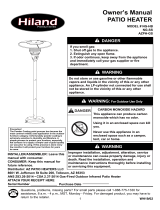
Step 1: Lay base on floor or sturdy table with socket assembly in vertical upright position.
Slide the 66” long stainless steel or painted post with rectangular access hole at the bottom of the post
over the round welded vertical socket on the base.
Align the post holes at the
bottom of the post with the
holes in the vertical socket
assembly. (See Figure #1)
Figure #1

© AEI CORPORATION 2009
12
Step 5: If the 3/8” x 3/8” flared brass fitting
is screwed into the shorter feed line hose please
remove it at this time and attach this fitting at the
base of the heater head. Tighten securely. Do not use any
pipe sealant at this brass to brass
connection. Do not over-tighten!
(See Figure #5)
Step 2: Slide 3” Vinyl sleeve down post.
Align the holes in the socket with the post
and vinyl sleeve. Insert lock washer, flat
washer, and screw into four holes.
Securely tighten the four stainless steel
screws with flat washers and lock washers
(lock washer is installed first against post
and then flat washer) at post to socket
connection. (See Figure #2).
Step 3: Slide 3” diameter stainless
steel slip collar over post. The slip collar
should now be at the bottom of the
post/socket assembly. The slip collar is
intended to cover the fasteners and vinyl
sleeve. (See Figure #3)
Figure #4
Step 4: Side decorative cover down the
post over slip collar. Be careful, this piece
has relatively sharp metal edges.
(See Figure #4)
Insert image 0688
Figure #2
#2A
Figure #3
Figure #5

© AEI CORPORATION 2009
13
Step 7: Secure head to feed line at this
time. Be sure the 3/8” x 3/8” flare
brass
fitting is tight where it connects at the
base of the heater head as well as at
the hose swivel fitting. No sealant is
required at these fittings. Do not
over-tighten. Brass to brass is an
excellent connection: Do not secure
head to post at this time. (See
Figure #7)
At this point we need to test for any possible gas leaks in the regulator assembly, quick couplers,
and head to feed line connection. This procedure has already been done at the factory but we want
to insure maximum safety so we will conduct a gas leak test just in case. To achieve the leak testing
we must attach the twelve-foot hose and couplers to the gas supply. If you are not comfortable
either hooking up the valve at the gas supply line or leak testing the unit you should contact a
licensed plumber, gas technician, gas fitter, or public utility.
Step 8: Since there are a variety of
possible gas supply configurations our
directions can only be general in nature.
1) First, shut off the flow of gas to the stub.
2) This can be accomplished at the stub if you
have a shut off on your stub. If not, you
will need to shut off the gas at its source
to your stub.
3) Attach the combination coupler/shut off
valve that we have provided with your heater
onto your ½” gas line. Your line may be
larger than ½” so it must be reduced to ½” in
order to attach the shut-off valve provided. This is a very safe, code approved, and
convenient systems so please do not try to modify it in any way.
Step 6: Insert shorter feed line hose
in through rectangular access hole at
the bottom of the post and feed it out
the top of the post. Make sure
end of hose and regulator feed line
assembly is visible through rectangular
access slot at bottom of post. This
assembly has been pre-assembled for
you and leak tested. Just to be safe,
we will ask you to leak test and double
check all fittings before using your new
heater. (See Figure #6)
Figure # 8
Figure # 7
Figure # 6

© AEI CORPORATION 2009
14
4) Use an approved pipe sealant or Teflon Gas tape to seal the connection from the stub to
the brass shut-off valve. (See Figure # 8)
Step 9:
1) With gas still shut off. Insert one of the 3/8” male nipple
fittings at end of the 12-foot hose into the coupler at the end
of the shut-off valve/coupler. (See Figure #9)
2) You can engage and disengage the couplers by just
sliding the ring back at the end of the coupler. The male
nipple at the ends of the hose should insert and disengage
easily.
3) The couplers can only work one way. When the unit is not in use you can leave the
hose attached to the heater or you disengage the hose set either at the heater or at the
fuel supply or at both points, (See Figure #9B). Please try to position the hose so that
it does not present a trip hazard.
Step 10: Final Safety Testing for Gas Leaks (See Figure #10)
1) The hose should be properly engaged at the quick disconnect coupler at the post
and at the house supply. Please turn the supply of gas ON.
2) Using a soapy solution carefully check each and every
brass fitting, quick coupler, and gas connection. Perform
the leak test from the valve to your house gas supply all
the way to the connections at the post. Also check where
the fitting at the feed line hose is attached to the heater
head. You should do this with a soapy water solution.
There should be no open flames or other sources of
ignition near you when performing the leak test.
3) Never do the gas leak test with an open flame!
4) If you see bubbles at any connection you have a leak.
Immediately Shut off gas at the source. This leak must be
remedied before going any further. Please re-tighten
leaking fitting and once again check with a soapy water solution. Most leaks are the
result of not tightening the fittings adequately.
5) If you cannot stop the leak you should shut off the gas immediately at the shut-off
valve and re-check your assembly. If you are still having trouble achieving a gas
tight connection you should call your Patio Comfort dealer or qualified gas
technician. All the of the key fittings and components are high quality brass fittings
and have been pre-
tested at the factory.
Figure # 9
Figure # 10

© AEI CORPORATION 2009
15
Step 12: You can now attach the heater head to
the post using four pan head screws
M6 X 12 provided. (See Figure #12)
Step 14: Be sure to attach the ring end of the blue
colored protective rubber plug onto the fitting
before inserting it into the gas inlet in the post. The
blue plug is designed to keep insects, dust, debris,
moisture, and other contaminants out of the feed
line, valve assembly, and pilot assembly when
heater is not in use. (See Figure #14)
Figure #13
Figure #14
Figure # 12
PLEASE NOTE Before the last assembly step of
securing the head to the post, align the head
and post and the gas inlet to minimize any
possible trip hazards. Always try to position
your heater and hose in a way as to minimize
trip hazards.
Step 11: If your unit passes the gas leak test
100%, you can now secure the access panel at the
bottom of the post with the four self-tapping pan-
head screws provided. When you install the screws
do not tighten any of them until all four screws are
inserted into the post.
(See Figure #11)
Figure #11
Step 13: You can now attach the reflector to the
heater head with three 8mm flat washers and wing
nuts provided.
(See Figure #13)

© AEI CORPORATION 2009
16
This hose, coupler, and shut-off valve assembly comply with all UL standards. DO NOT attempt any
modifications to this hook-up.
You have now finished the assembly of the heater. We have tried to design your Patio Comfort heater
with the finest materials and safety systems available. Please do not try to modify any part of the
product, the feed line assembly, natural gas regulator, or quick disconnect connections.
These are high quality components designed to provide you with maximum convenience and flexibility
and more importantly to maximize the safety to you and your family.
Our unique double quick connect system allows you to safely detach the hose set from the heater
when not in use. If your dealer has not included this hook-up kit with your heater go back to the dealer
and insist that they provide it to you. The hose kit is an integral part of the heater and will add greatly
to the safety and convenience of the product.
Step 15: Always be sure to use the dust plug
when the heater is not in use.
(See Figure #15)
Step 16: Please Note: The end of the hose set that
attaches to your home natural gas supply also has a
quick disconnect coupler and state of the art shut- off
safety valve for your safety and convenience. As an
added feature when the“ON and OFF” black control
knob on the shut-off valve is in the “ON” position you
cannot inadvertently remove the hose from the coupler
while the heater is in operation. (See Figure #16)
Figure #16
Step 17: If your patio heater is being placed in a
location or on a surface where you have concerns
over it being tipped or knocked over during operation
we have provided three optional mounting brackets
with screws for your use. If the heater will be used in
a commercial application these brackets may be
required. (See Figure #17) Please check your local
codes.
Figure #15
Figure #17

© AEI CORPORATION 2009
17
Before using your heater for the first time please review the following:
NEVER RUN THIS APPLIANCE ON PROPANE FUEL OR
ATTEMPT TO CONVERT IT TO PROPANE OR LIQUIFIED
PETROLEUM FUELS. THIS HEATER IS ONLY DESIGNED
TO BE OPERATED ON NATURAL GAS.
THIS PRODUCT CANNOT BE CONVERTED TO PROPANE GAS.
Please keep in mind that every time you connect your heater for the first time and every time
you reconnect the 12-foot hose to the heater you must first bleed the air from the fuel feed line
and hose. This is done by turning on the gas at the source and turning the valve at the heater
to the “PILOT” position.
You may need to depress the valve control knob on the heater in the PILOT position for at
least one to two minutes to bleed the air before attempting to light the PILOT light with the
ignitor.
The safety pilot system has a very small orifice size and it may take up to two minutes to bleed
all of the air out of the line. After purging the air, depress the igniter button and you will hear
the pilot light. You can also visually see it through the vents in the base of the heater head or
through the small access hole with cover plate on the base of the heater head.
A FEW WORDS ABOUT NATURAL GAS:
First, natural gas is a safe, clean, convenient, and cost-effective fuel. You will never have to
worry about running out of fuel for your natural gas heater in the middle of an outdoor event.
The heater is set to operate 4.5” W.C. No attempt should be made to modify any of the
components included with your Patio Comfort Natural Gas heater.
Remember any hose or connector can be a potential trip hazard and
should be positioned in a way where it presents the least potential trip
hazard. The hose can be easily removed from the heater using the quick
couplers included. Never attempt to move the heater while it is in
operation. This heater is for OUTDOOR USE ONLY.

© AEI CORPORATION 2009
18
In most areas of the U.S. and Canada, Natural Gas pressure in residential settings is adequate
to fuel patio heaters, outdoor gas grills, gas lights, pool heaters, etc. In some of the older
areas in the West, parts of New England, and the Mid-Atlantic areas gas pressures may be too
low to allow for this product (or any natural gas appliance) to operate at its full performance
levels. If you feel that this may be the case in your home you should first check with your
local natural gas public utility. You may have to run a larger fuel pipe to adequately power this
and possibly other backyard cooking, heating, or decorative natural gas burning appliances.
If you have inadequate gas volume using multiple appliances at the same time may impact the
heat output or performance of the various appliances.
We have designed this heater to provide you and your family with many years of use. If you
have any questions whatsoever about the assembly, installation, or use of this product please
contact your selling dealer or distributor before using this product.
Placement of the Heater
Your Patio Comfort outdoor patio heater is designed for use as temporary comfort heating for
your outdoor patio, outdoor decks, outdoor spa areas, pool areas, and other outdoor areas with
plenty of fresh air.
The heater is NOT designed, approved, or intended for indoor use or enclosed area use such
as a garage, commercial building, basements, tents, ice fishing tents, prefabricated buildings
or enclosures or other enclosed areas.
The heater is also not designed for use on moving objects or vehicles such as houseboats,
yachts, travel trailers, boats, or other moving devices or vehicles.
The minimum clearances from combustibles must be maintained at all times. We recommend
the heater be no closer than 27 inches from any combustible vertical or horizontal wall or have
any combustible material within 20 inches of the top of the reflector.
Placement of the Heater-Continued
Wall/ or
other
Combustible
Materials
27”
Minimum
20” Minimum
“Combustibles” include Lattice, Wood, Plants, Umbrellas, Canopies, Awnings, or other
Combustible Materials

© AEI CORPORATION 2009
19
These minimum clearances from combustible materials must be maintained at all times when
the patio heater is in operation.
The heater must always be used on firm, level, and stable ground. Never move the heater while
it is in operation. Never try to hook up multiple feed line hoses together.
WARNING: Never operate heater in an explosive atmosphere and be sure
to keep unit away from where gasoline or other flammable liquids or vapors are
stored or used.

© AEI CORPORATION 2009
20
Lighting Instructions
Before turning on the natural gas fuel supply, visually inspect the hose assembly for evidence of excessive
abrasion, cuts, cracking, animal damage, or unusual wear and tear. If the hose leaks do not attempt to use the
heater, replace the hose immediately. Only use replacement hoses and other parts as specified by Patio
Comfort.
Before Lighting
If attempting to relight a hot heater, always wait at least five minutes. The main heater components such as the
emitter grid, gas hook up, and pilot assembly should be checked at least every two years by a qualified service
technician or immediately if you feel the appliance is not working properly.
To Light Heater
1) Be sure the control knob on the heater head is in the “OFF” position.
2) Turn the shut off valve at the house connection in a counter-clockwise direction to open. Be sure the quick
connect couplers at the heater post and end of the hose at the shut-off are fully engaged and tight. If the
couplers are not properly engaged, no gas will flow to the heater.
3) Gently depress the control knob on the control panel and rotate it counter clockwise to the “PILOT” position.
4) This is very important! Gently depress the control knob and hold the control knob to begin the flow
of gas to the burner pilot assembly. Depress the control knob in the “PILOT” position for up to 2 minutes
on new installations or reconnected hoses. This is how long it might take for the air to be purged from
the hoses and feedline delivery system. It will take less than 10 seconds for regular relighting. Do NOT
continually press on the igniter while you are purging the line. This will only cause premature wear and
tear on the ignition and weaken the charge created by the piezo ignition. Occasionally depress the igniter
and you will hear when the pilot light ignites. You can also see the pilot light through the pilot access port
that has a small rectangular cover at the base of the heater head. This is essentially the same safety system
that you have on your water heater. Please be patient with this process. You can also hear the pilot light
when it lights.
5) Once the pilot is lit, continue to depress the control valve for about 20 seconds or until the pilot flame
remains lit after the control knob is released.
6) The burner may now be turned on to the full “ON” position for maximum heat output or it may be turned
back to the “PILOT” position to reduce heat output and fuel consumption. If you turn the control knob all the
way back to the “PILOT” position, the main burner will go off and the pilot flame will remain lit. You can now
re-ignite the main burner directly from the “PILOT” position. On the first use, a little smoke is to be expected.
This is machining oils being burned off.
The heater is designed to be operated in the full “ON” position only. Turning the
heater down will result in incomplete combustion and sooting of the burner and
very low heat output. You can immediately re-light the main burner when the
standing pilot is on.
/