AnyTone Dual Band FM Transceiver User manual
- Category
- Car media receivers
- Type
- User manual
This manual is also suitable for

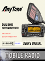
DUAL BAND
FM TRANSCEIVER
USER'S MANUAL
www.at-5888uv.com
groups.yahoo.com/group/AT5888UV
REV 2.0 2/2013

Dual Band Mobile Radio Applicable Software: QPS5888UV_S1
Model Apply To This Manual: Dual Band Mobile Radio
Nice Housing, Stoutness & Stability, Advanced and Reliable
functions, Perfect & Valuable.
Approval. Dual Band
mobile radio especially designs for drivers and it pursues company
philosophy of innovation and practicality.
NOTE
www.at-5888uv.com

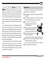
Precautions
Please observe the following precautions to prevent fire,
personal injury, or transceiver damage:
Do not attempt to congure your transceiver while driving,it
is dangerous.
This transceiver is designed for a 13.8V DC power supply.
Don't use a 24V battery to power on the transceiver.
Do not place the transceiver in
excessively dusty, humid or wet areas,
nor unstable surfaces.
Please keep it away from interferential
devices (such as TV, generator etc.)
Do not expose the transceiver to long
periods of direct sunlight nor place it
close to heating appliances.
If an abnormal odor or smoke is detected coming from the
transceiver, turn OFF the power immediately. Contact an
Anytone service station or your dealer.
Do not transmit with high output power for extended
periods; the transceiver may overheat.
Thank you for choosing this mobile transceiver,
always provide high quality products, and this
transceiver is no exception. The transceiver is a ruggedly-built,
high quality Dual band FM transceiver providing 50 Watts of
power output on the VHF band and 40 Watts on the UHF band. It
owns many advanced characters like cross band repeat function,
built with a direct-ow heat sink and thermostatically-controlled
cooling fan maintaining a safe temperature for the transceiver's
circuit.
Dual band mobile radiao has four independent receiving
bands, consist of UU, UV,VU,VV for dual receive and dual
output, plus receiving for AM/FM signal of air band, marine band,
PMR, etc.also able to receive FM/TV radio and analogue TV
signal. It owns 758 memory channels, full duplex operation with
independent volume and squelch controls, compander and built-
in CTCSS/DCS, DTMF, 5TONE,2TONE signaling, detachable
front panel for exible installation.
Though friendly design for user, this transceiver is technically
complicated and some features may be new to you. Consider
this manual to be a personal tutorial from the designers,allow the
manual to guide you through the learning process now, then act
as a reference in the coming years.
www.at-5888uv.com

CONTENTS
New and Innovative Features ...................................................1
Frequency Range ...................................................................1
Supplied Accessories/Optional Accessories ..........................2
Supplied Accessories ..............................................................2
Optional Accessories ..............................................................2
Initial Installation .......................................................................3
Mobile installation ...................................................................3
DC Power Cable Connection ..................................................4
Antenna Connection ...............................................................6
Accessories Connections ........................................................7
Getting Acquainted ...................................................................8
Front panel ..............................................................................8
Rear panel ..............................................................................9
DISPLAY .................................................................................9
microphone ...........................................................................10
Basic Operations .....................................................................11
Switching The Power On/Off .................................................11
Adjusting The Volume ..........................................................11
Switch between VFO and Channel mode ............................. 11
Adjusting Frequency .............................................................11
Adjusting Channel ................................................................. 11
Switch Between Main Band and Sub band ...........................12
Selecting the frequency band ...............................................12
Receiving ..............................................................................12
Squelch Off/Squelch Off Momentary.....................................12
Transmitting ..........................................................................12
Shortcut Operations ................................................................13
Squelch level Setup ..............................................................13
Transmit DTMF/2TONE/5TONE signaling ............................13
High/Mid/Low Power Switch .................................................13
Frequency Reverse ...............................................................13
Band-width Selection ............................................................13
Home Channel ......................................................................13
Hyper Memory channel .........................................................13
Dual Watch............................................................................14
Emergency Alarm ..................................................................14
Channel/Frequency Scan .....................................................14
Channel Scan Skip ...............................................................14
Channel Edit .........................................................................14
Scan range Limit ..................................................................14
Channel Copy .......................................................................14
Channel Delete .....................................................................15
General Setting ........................................................................16
APO (Automatic Power off) ...................................................16
Automatic offset ....................................................................16
Frequency Channel Step Setup ............................................16
VFO Band lockout .................................................................17
Beep Function .......................................................................17
CPU Clock frequency Change ..............................................17
2TONE Encode select ..........................................................17
5TONE Encode select ..........................................................18
Add Optional signaling ..........................................................18
CTCSS encode Setup ..........................................................18
CTCSS decode Setup ...........................................................19
Sub Band Display Setup .......................................................19
DTMF Encode Pre-Loading time ..........................................19
DTMF Encode Transmitting Time .........................................20
DTMF Encode setup .............................................................20
www.at-5888uv.com

Squelch Mode Setup .............................................................20
Compander ...........................................................................21
Scrambler Setup ...................................................................21
Tone Burst (Pilot Frequency) ................................................21
Keypad Mode Setup .............................................................22
Keypad Lockout ....................................................................23
TX OFF (PTT Lockout) .........................................................23
Squelch Level setup ..............................................................23
Frequency Reverse ...............................................................23
Sub band mute setup ............................................................24
Editing Channel Name ..........................................................24
Channel Function Auto storeage Setup ................................24
Microphone PA,PB, PC,PD key setup ..................................25
RF Squelch level setup .........................................................25
OFFSET Direction setup .......................................................25
Scan Dwell Time Setup .........................................................25
Priority channel scan .............................................................26
Offset frequency Setup .........................................................26
Display mode Setup ..............................................................26
Busy Channel Lockout ..........................................................27
Radio's DTMF SELF ID ENQUIRY .......................................27
5TONE SELF ID ENQUIR ....................................................27
TOT (Time-out timer) ............................................................27
VFO Frequency Linkage .......................................................28
Wide/Narrow band ................................................................28
Cross Band repeat ................................................................28
LCD backlight ........................................................................28
Keypad backlight brightness .................................................29
Calling Record ......................................................................29
AM Function ..........................................................................29
Automatic AM function ..........................................................29
VHF External speaker port ....................................................30
BEEP Volume control ..........................................................30
Talk Around........................................................................... 30
Microphone speaker............................................................. 30
Password Function ...............................................................30
Microphone Operation ............................................................31
Send DTMF signaling ...........................................................31
Main/Sub band switching ......................................................31
Function operation through PA-PD keys ...............................31
Cable Clone ..............................................................................33
Resume Factory Default .......................................................33
Programming Software Installing and Starting ....................34
Install USB Cable Driver Programme ...................................34
Maintenance .............................................................................35
Default Value For Factory Resume ......................................35
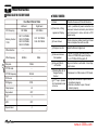
Trouble Shooting ...................................................................35
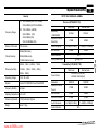
Specications ..........................................................................36
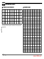
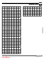
Attached Chart .........................................................................37
51 groups CTCSS Tone Frequency(Hz) ...............................37
1024 groups DCS Code ........................................................37
CONTENTS
www.at-5888uv.com

1
1
Dual Band Mobile Radio has nice housing, stoutness & stability, advanced and reliable functions, perfect & valuable. This amateur mobile radio
especially designs for drivers and it pursues company philosophy of innovation and practicality. More functions as follows:
758 memory channels, full duplex operation with independent volume and squelch controls
50 Watts of power output on the VHF band and 40 Watts on the UHF band with cross band repeat function.
Four independent receiving bands, consist of UU, UV,VU,VV for dual receive and dual output, plus receiving for AM/FM signal of air band,marine
band, PMR, etc; able to receive FM/TV radio and analogue TV signal (Optional).
Display on a large LCD with adjustable brightness, convenient for nighttime use. There are Amateur operation mode and Professional operation
mode for option.
Distribute buttons reasonably, convenient for operation. Adopt superior quality material, better technology and direct-ow heat sink to ensure
stable and durable operation.
758 programmable memory channels, identied by editing name.
Programming different CTCSS, DCS, 2Tone, 5Tone per channel, rejecting extra calling from other radios.
Various scan functions including CTCSS/DCS Scan function.
Using 5Tone to send Message, Emergency alarm, Call all, ANI, Remotely kill, Remotely Waken, etc.
Automatic calling ldentication function by DTMF--ANI or 5Tone--ANI .
Multi groups of xed scrambling and 2 groups of self dened scrambling.
Compander function for decrease the background noise and enhance audio clarity, it can set compander ON/OFF per channel.
Different band width per channel, 25K for wide band, 20K for middle band ,or 12.5K for narrow band.
Theft alarm provides extra safety.
Frequency Range
RX: 108~180MHz(AM/FM) TX: 144~146 MHz EXP(136~174MHz)
220~260MHz 430~440MHz EXP( 400~490MHz)
350~399.995MHz
400~490 MHz
New and Innovative Features
www.at-5888uv.com

2
2
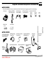
Supplied Accessories/Optional Accessories
SUPPLIED ACCESSORIES
OPTIONAL ACCESSORIES
After carefully unpacking the transceiver, identify the items listed in the table below. We suggest you keep the box and packaging.
Transceiver
Spare Fuses
(QF-01)
User Manual
3 meter extending cable
fo r att ach abl e pan el/
Cloning Cable(CP52)
Programming Software
(QPS5888UV_S1)
Car Antenna
(QCA-02)
Mobile Mounting
Bracket (QMB-01)
DC Power Cable with
Fuse Holder(QPL-01)
Microphone (QHM-05)
(with DTMF keyboard)
Microphone
(QHM-02)
S-Washer
(QSS-01D)
Hardware Kit for Bracket
Black screws
(M4X8mm)
4PS(QSS-01A)
Tapping screws
(M5X8mm)
4PS(QSS-01B)
USB Programming
Cable (PC51)
Cigar-Plug Connection
Line (QCC-01)
Desktop
Microphone
(QDM-01)
Power supply (QRP-01) Front Panel Bracket
(QMB-03)
External Speaker (SP-02)
www.at-5888uv.com

3
3
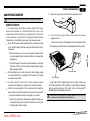
MOBILE INSTALLATION
To install the transceiver, select a safe, convenient location inside your
vehicle that minimizes danger to your passengers and yourself while the
vehicle is in motion. Consider installing the unit at an appropriate position
so that knees or legs will not strike it during sudden braking of your
vehicle. Try to pick a well ventilated location that is shielded from direct
sunlight.
Install the mounting bracket in the vehicle using the supplied self-
1.
tapping screws (4pcs) and at washers (4pcs).
Position the transceiver, then insert and tighten the supplied hexagon
2.
SEMS screws.
Car body
Mounting bracket
Washer (M5)
Tapping screw
(M5X20mm)
Doubl e check that all scr ews are tighte ned to prev ent
vehiclevibration from loosening the bracket or transceiver.
Initial Installation
Determine the appropriate angle of the transceiver, using the 3
screw hole positions on the side of the mounting bracket.
www.at-5888uv.com

4
3
Initial Installation
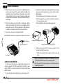
DC POWER CABLE CONNECTION
Locate the power input connector as close to the transceiver as possible.
MOBILE OPERATION
The vehicle battery must have a nominal rating of 12V. Never
connect the transceiver to a 24V battery. Be sure to use a 12V
vehicle battery that has sufficient current capacity. If the current
to the transceiver is insufficient, the display may darken during
transmission, or transmitting output power may drop excessively.
Route the DC power cable supplied with the transceiver directly
1.
to the vehicle's battery terminals using the shortest path from the
transceiver.
We recommend you do not use the cigarette lighter socket
as some cigarette lighter sockets introduce an unacceptable
voltage drop.
The entire length of the cable must be dressed so it is isolated
from heat, moisture, and the engine secondary (high voltage)
ignition system/ cables.
After installing cable, in order to avoid the risk of damp, please
2.
use heat-resistant tap to tie together with fuse box. Don't forget
to reinforce whole cable.
In order to avoid the risk of short circuit, please cut down
3.
connection with negative (-) of battery, then connect with radio.
Conrm the correct polarity of the connections, then attach the
4.
power cable to the battery terminals; red connects to the positive
(+) terminal and black connects to the negative (-) terminal.
Use the full length of the cable without cutting off excess even
if the cable is longer than required. In particular, never remove
the fuse holders from the cable.
Reconnect any wiring removed from the negative terminal.
5.
Connect the DC power cable to the transceiver's power
6.
supplyconnector.
Press the connectors rmly together until the locking tab clicks.
If the ignition-key on/off feature is desired(optional feature),use the
Red
Black
optional QCC-01(For Cigar-Plug connection) cable. Connect one
of the cables between the ACC terminal or a Cigar-Plug that operates
with the vehicle ignition or ACC switch on the vehicle and EXT
POWER jack on the rear side of the unit.
Ext. Power jack
DC power cable
In many cars,the cigar-lighter plug is always powered. If this is the case,
you cannot use it for the ignition key on/off function.
NOTE
NOTE
www.at-5888uv.com

5
When the ignition key is turned to ACC or ON(Start) position
7.
with the radio turned off, the power switch illuminates. The
illumination will be turned off when the ignition key is turned
to the off position.To turn on the unit, press the power switch
manually while it is illuminated. (While ignition key is at ACC or
ON position)
3
Initial Installation
When the ignition key is turned to ACC or ON position with the
8.
radio's power switch on, the unit turns on automatically and the
power switch will be lit. Turn the ignition key to OFF position or
manually turn the power switch off to shut down the radio.
Using extra cable,power consumption:5MAH.
9.
Without this function,user can turn on/off radio by Power knob.
10.
Ext. Power jack
Cigar-Plug connection
ACC terminal
Do not directly connect the transceiver to an AC outlet.
Use the supplied DC power cable to connect the transceiver
to a regulated power supply.
Do not substitute a cable with smaller gauge wires.
FIXED STATION OPERATION
In order to use this transceiver for fixed station operation, you
will need a separate 13.8V DC power supply (not included) , power
supply( QRP-01) as optional accessories. Please contact local
dealer to require.
The recommended current capacity of your power supply is 12A.
Before connecting the DC power to the transceiver, be sure to
switch the transceiver and the DC power supply OFF.
Do not plug the DC power supply into an AC outlet until you
make all connections.
Regulated power supply (QRP-01)
DC power cable with fuse holder (QPL-01)
Black
Red
Regulated
power supply
(QRP-01)
Connect the DC power cable to the regulated DC power supply
1.
and ensure that the polarities are correct. (Red: positive,
Black:negative).
Connect the transceiver's DC power connector to the
2.
connector on
the DC power cable.
Press the connectors rmly together until the locking tab
clicks.
NOTE
www.at-5888uv.com

6
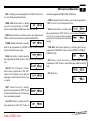
If the fuse blows, determine the cause, then correct the problem.
After the problem is resolved, replace the fuse. If newly installed
fuses continue to blow, disconnect the power cable and contact your
authorized dealer or an authorized servicecenter for assistance.
Only use fuses of the specified type and rating, otherwise the
transceiver could be damaged.
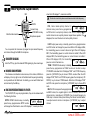
Before operating, install an efcient, well-tuned antenna. The success
of your installation will depend largely on the type of antenna and its
correct installation. The transceiver can give excellent results if the
antenna system and its installation are given careful attention.
Use a 50Ω impedance antenna and low-loss coaxial feed-line that
has a characteristic impedance of 50 Ω, to match the transceiver input
impedance. Coupling the antenna to the transceiver via feed-lines having
The possible locations of antenna on a car are shown as following:
3
Initial Installation
REPLACING FUSES
If you use the transceiver for a long period when the vehicle battery is
not fully charged, or when the engine is OFF, the battery may become
discharged, and will not have sufcient reserves to start the vehicle. Avoid
using the transceiver in these conditions.
Transmitting without first connecting an antenna or other
matched load may damage the transceiver. Always connect
the antenna to the transceiver before transmitting.
All xed stations should be equipped with a lightning arrester to
reduce the risk of re, electric shock, and transceiver damage.
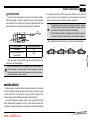
Fuse Location Fuse Current Rating
Transceiver 15A
Supplied Accessory DC
power cable
20A
ANTENNA CONNECTION
an impedance other than 50Ω reduces the efficiency of the antenna
system and can cause interference to nearby broadcast television
receivers, radio receivers, and other electronic equipment.
NOTE
NOTE
www.at-5888uv.com

7
3
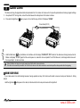
If you plan to use an external speaker, choose a speaker with an
impedance of 8 Ω. The external speaker jack accepts a 3.5 mm (1/8")
mono (2-conductor) plug.
For voice communications, connect a microphone equipped with
an 8-pin modular plug into the modular socket on the front of the
main unit. Press rmly on the plug until the locking tab clicks. Attach
the supplied microphone hanger in an appropriate location using the
screws included in the screw set.
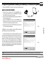
To untilize the QPS5888UV_S1 software, you must first connect
the transceiver to your PC then using an optional programming cable
PC50 (via Data socket ).
Please use QPS5888UV_S1 software for programming.
Initial Installation
EXTERNAL SPEAKER
MICROPHONE
PC CONNECTING
Ask your dealer about purchasing a Programming Cable PC51.
ACCESSORIES CONNECTIONS
SP-02
http://www.qxdz.cn
External speaker[SP-02]
Microphone[QHM-04]
Antenna[QCA-02]
NOTE
Microphone
connector
www.at-5888uv.com

8
4
Basic Functions•
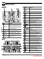
NO. KEY FUNCTION
1 Left Dial Knob
Rotate it to choose frequency /channel. Press
it to set the left band as "Main Band"; In VFO
mode, press it to choose the frequency band;
In function setup as conrm key; in scan mode,
rotate it to change scan direction
2 Right Dial Knob
Rotate it to choose frequency /channel. Press
it to set the right band as "Main Band"; In VFO
mode, press it to choose the frequency band;
In function setup as conrm key; in scan mode,
rotate it to change scan direction
3 Left Volume Knob Adjust left band volume level.
4 Right Volume Knob Adjust right band volume level.
5
【
TV/SQL
】
In standby. press this key to turn On/Off TV
function.Hold this key to cancel squelch
Getting Acquainted
FRONT PANEL
6 Function set Key In standby , press this key to enter function menu
7 PWR Press it to power On /Off the transceiver
8 Left
【
LOW
】
Key
In standby press it to change H/L power for present
channel.Long press it to turn On/Off
Function
9 Left
【
V/M
】
Key
In standby, press it to switch between channel
mode and VFO mode. Long press it to set Wide/
Narrow band.
10 Left
【
HM
】
Key
In standby, press it to switch between HOME
channel and normal channel. Long press it to
enter dual watch of VFO channel and current
channel.
11 Left
【
SCAN
】
Key
In standby, press it to start channel or frequency
scan.In channel mode, hold it to set current
channel scan skip.
12 Right
【
LOW
】
Key
In standby press it to change H/L power for
present channel.Long press it to turn On/Off
Frequency Reverse Function
13 Righ
【
V/M
】
Key
In standby, press it to switch between channel
mode and VFO mode. Long press it to set Wide/
Narrow band.
14 Righ
【
HM
】
Key
In standby, press it to switch between HOME
channel and normal channel. Long press it to
enter dual watch of VFO channel and current
channel.
15 Righ
【
SCAN
】
Key
In standby, press it to start channel or frequency
scan.In channel mode, hold it to set current
channel scan skip.
16 LCD
For display of channel, frequency and function
setup.
Frequency
Reverse
www.at-5888uv.com

9
4
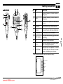
NO. KEY FUNCTION
1 Ext. Power Jack
Terminal for connecting optional cable QCC01 for
use with ignition key On/Off function.The radio will
auto power on when car is driving. The radio will
auto power off when car stops.
2 Ext.Speaker Terminal
Terminal for optional external speaker SP02
3 TV/AV port
Connect to television TV/AV port
. (
Optional)
4 Heat -sink fan
Runs Automatically when radio temperature rise up.
5 Antenna Connector
Connect a 50 Ω antenna
NO. INDICATOR FUNCTION
1
Displays the channel number and Menu number.
2
Appears when current channel is priority channel
3
Appears when current channel is set Scan Skip
4
Appears when current channel has CTCSS Encode
5
Appears when current channel has CTCSS Decode
6
Appears when the Offset function is ON
7
Appears while transmitting.
8
Displays the Main channel.
9
Displays the operating frequency,channel name
10
Displays when receiving a signal or Monitor is ON
11
Signal strength for receiving and power level for
transmitting
12
Appears while in Narrow band.
13
Appears when mute has been turned ON.
14
Appears when the DCS function is ON.
15
Appears while in AM mode
16
Appears when the Scrambler function is ON
17
Appears when the Compander function is ON.
18
Appears while using Low output power
19
Appears while using Middle output power
20
Appears while Auto power off function is ON.
21
Appears when the Key Lock function is ON.
22
Appears when press SET key.
23
Appears when choose KEY2 mode.
24
Appears when corss band repeat function is ON
Getting Acquainted
REAR PANEL
DISPLAY
4 132
1 1
10
11
11
12 1213 1314 1415 1616
21
22
17 1718 1819 19
20
23
24
9
8
2 534 6 7
8
2 534 6 7
99
www.at-5888uv.com

10
4
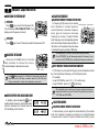
MIC Connector Diagram(in the front view of connector)
Getting Acquainted
MICROPHONE
Key Pad Serial Data
+5V
DOWN
UP
MIC GND
MIC
PTT
GND
1
2
10
3
5
6
9
7 8
4
NO. KEY FUNCTION
1 UP
Increase frequency ,channel number or
setting value.
2 DOWN
Decrease frequency, channel number or
setting value.
3 PTT
Pre ss the PTT ( Pus h-TO -Talk ) k ey to
transmit.
4 Number Key Input VFO frequency or DTMF dial out etc.
5 A/B band Choose left band or right band as Main band
6 Band indicator The indicator light on for Main band.
7 TX/RX indicator
Light green while receiving, Light red while
transmitting.
8 MIC Speak here during transmission.
9
Speaker
When shut the speaker in the base, you can
hear the calling by this speaker.
10
Lock UP/down
When this key is in up position, It is unlock
UP/DOWN key, when this key is in down
poisition, UP/DOWN key will be locked.
www.at-5888uv.com

11
In frequency (VFO) mode, turn the selector
knob clockwise to increase frequency;
counterclock-wise to decrease frequency.
Every gear will increase or decrease
frequency by one step. To adjust the Main
band frequency, press corresponding selector
knob, the left side of decimal point will ash. In
this status, turn the selector knob will increase
or decrease frequency quickly by 1MHz step
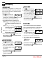
ADJUSTING FREQUENCY THROUGH SELECTOR KNOB
INPUT FREQUENCY THROUGH MICROPHONE NUMBER KEY
In standby, press corresponding key to
switch between Frequency and channel mode,
when the transceiver is in channel mode, the
LCD will display current channel.
5
Basic Operations
POWER ON
Press key to switch the transceiver ON,
the LCD displays "WELCOME ANYTONE", then
display current frequency or channel.
POWER OFF
Press key for over 0.5 Second to switch the transceiver OFF.
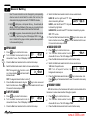
Rotate the [VOLUME] knob of selected
band clockwise to increase the volume,
counterclockwise to decrease the volume.
SWITCHING THE POWER ON/OFF
ADJUSTING THE VOLUME
SWITCH BETWEEN VFO AND CHANNEL MODE
ADJUSTING FREQUENCY
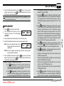
Hold ,keep pressing it to Monitor the background noise after the
transceiver emits a DU beep, meanwhile adjust the [VOLUME] knob.
During communication, volume can be adjusted more accurate.
The microphone
[
UP/DOWN
]
key also able to adjust frequency.
Press
[
UP/DOWN
]
key will increase(decrease) the frequency by one
step size. Hold
[
UP/DOWN
]
key will adjust the frequency continuously.
When the Band lockout function is on, the input or adjusting of frequency
bandwill limit within the current VFO band. The right band only limited in
136-174Mhz and 400-470Mhz.
Decrease frequency
Increase frequency
In VFO mode, you can input the frequency by the microphone numeric
key. It is invalid to input frequency out of the frequency band.
For example:
to input 150.125Mhz, press 1, 5, 0, 1, 2, 5 continuously.
to input 152 MHz, press1, 5, 2,
continuously.
ADJUSTING CHANNEL
ADJUSTING CHANNEL THROUGH SELECTOR KNOB
In channel mode, you can adjust the channel directly by the channel
knob.Turn clockwise to increase one channel; turn counterclockwise
to decrease one channel.To adjust the Main band channel, press
Power
Min
Volume
Max
Volume
NOTE
NOTE
NOTE
www.at-5888uv.com

12
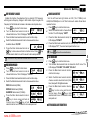
SWITCH BETWEEN MAIN BAND AND SUB BAND
SELECTING THE FREQUENCY BAND
If there is any empty channel, the adjustment will ignore it and jump to
next channel.
This transceiver can be set working on 2 UHF band or 2 VHF band.
INPUT CHANNEL THROUGH MICROPHONE NUMBER KEY
In channel mode, you can switch to desired channel by press 3 of the
microphone numeric keys (001-758). For example input 001 get channel 1;
input 030 is channel 30; input 512 is channel 512. If the input channel is
not programmed with frequency, the transceiver will emit a warning beep
and return to last channel.
This transceiver is default on dual receive,
a "MAIN" icon will display in the top right of
the working frequency. The transmitting is
only available on the Main band. When the left
Band is Main band, press the right selector
knob will switch the right Band to Main band. Then press the left selector
knob will switch the left Band to Main band.
1. Choose for Left band: press the left side
key to switch it to VFO
mode, press the left selector knob over 1 second then repeat above
operation will switch the left band between 108~180Mhz (RX: 108-
174Mhz, TX: 136-174Mhz), 220~260Mhz (RX only), 350~399.995Mhz
(RX only) or 400~490Mhz.
2. Choose for right band: press the right side key to switch it to
VFO mode, press the right selector knob over 1 second then repeat
above operation will switch the right band between 136-174Mhz,
400~490Mhz.
5
Basic Operations
RECEIVING
If the transceiver has set at higher squelch level, it may fail to hear the
calling. If the
“BUSY”
and signal strength icon display in left band or
right band, but can not hear the calling, means the signal is with matching
carrier but dis-matching signaling.
In standby, both left band and right band are
able To receive. When they receive any signal,
the “BUSY” icon and signal strength icon will appear
in the corresponding
area of the LCD. And you can hear the calling。
SQUELCH OFF/SQUELCH OFF MOMENTARY
Long press of key can be programmed as Squelch Off or Squelch
Off Momentary to monitor the weak signal.
1. Squelch Off: Hold key until hear "Du" beep, the squelch is off,
repeat the above operation to resume squelch.
2. Squelch Off Momentary: Keep hold key to disable squelch,
release the key to resume squelch.
TRANSMITTING
Hold “PTT” key, the transceiver change to transmitting. Please hold
the Microphone approximately 2.5-5.0cm from your mouth, and then
speak into the microphone in your normal voice to get best timbre.
The transmitting only available on Main band, the “TX” icon will display in
the top right corner of the Main band frequency
.
In standby, press the microphone
to cancel squelch, press it again
to turn on the squelch.
correspondent selector knob, the channel number flashes in this
situation, the channel number will increase 10 channels by each gear of
selector knob. Press microphone
[ UP/DOWN ] key also able to adjust
the channel.
NOTE
NOTE
NOTE
NOTE
NOTE
www.at-5888uv.com

13
6
Shortcut Operations
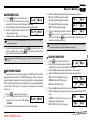
SQUELCH LEVEL SETUP
This function is used to setup the strength of receiving signal, when the
strength reach a certain level, the calling can be heard, otherwise, the
transceiver will keep mute.
In standby, press and hold
key, meanwhile switch the selector
knob to adjust the squelch level of Main band.
1-20: Total 20 squelch levels available.
OFF: turn off squelch. The background noise always on.
The squelch level shall setup separately for right band and left band.
TRANSMIT DTMF/2TONE/5TONE SIGNALING
If the current channel is with DTMF/2TONE/5TONE signaling, hold PTT
and
[ UP ] key will transmit selected Pre-programmed signaling
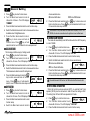
HIGH/MID/LOW POWER SWITCH
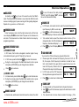
In standby, repeat press key to choose power levels as following:
When LCD displays HIGH, the power for current channel is high.
When LCD displays MID1, the power for current channel is middle 1
When LCD displays MID2, the power for current channel is middle 2.
When LCD displays LOW, the power for current channel is low.
Output power for each level:
HIGH MID1 MID2 LOW
VHF(50W) VHF(20W) VHF(10W) VHF(5W)
UHF(40W) UHF(25W) UHF(10W) UHF(5W)
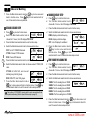
In channel mode, this operation is for temporary use only
This function is valid only when current channel setup with offset frequency
and offset direction
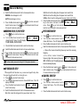
In standby, press key to switch to
HOME channel, and communicate on HOME
channel. repeat pressing it to return to last
channel.
In standby, hold
key for over 0.5second to turn On/ Off frequency
reverse function. When reverse function is on, the TX frequency will
change to RX frequency and RX frequency change to TX frequency.
The signaling will also be reversed if CTCSS/DCS signaling existed in
this channel.
HOME CHANNEL
FREQUENCY REVERSE
This transceiver has 3 band widths, select suitable band width in
accordance with different local conditions.
In standby, hold key for over 0.5 second to choose the 3 band widths
When LCD displays WIDE, current channel is working on wide band
25KHzWhen LCD displays MIDDLE,current channel is working on middle
band 20KHzWhen LCD displays NARROW, current channel is working on
narrow band 12.5KHz
BAND-WIDTH SELECTION
NOTE
NOTE
NOTE
HYPER MEMORY CHANNEL
In standby, press the left or right volume knob will switch the radio work
on hyper channel 1 or hyper channel 2.
www.at-5888uv.com

14
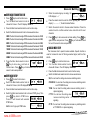
Shortcut Operations
In standby, hold key for over 0.5 second to enter Dual Watch
mode. The radio will scan the channel in every 5 seconds. When the radio
receives matching signal, it pause scanning until the signaling disappear.
Repeat
above operation to exit Dual watch.
DUAL WATCH
FREQUENCY SCAN
CHANNEL/FREQUENCY SCAN
In VFO mode, this function is designed to monitor signal of every
communicative frequency point of "step size" you have set.
In VFO mode, press the Main Band
1.
key to enter channel scan.
During the scanning adjust the Main band selector knob or press
2.
microphone
[ UP/DOWN ] key will change the scan direction.
Press
3.
key to exit scan.
CHANNEL SCAN
In channel mode, press the Main Band
1.
key to enter channel scan.
During the scanning, adjust the Main band selector knob or press
2.
microphone [ UP/DOWN ] key will change the scan direction.
Press
3.
key to exit scan.
In channel mode, switch selector knob to choose the channel, then hold
In VFO mode, turn selector knob to select the desired frequency or
1.
input frequency by MIC's numeric keys.
Hold
2.
key until the transceiver prompt
DU and the display of channel number ashes.
Turn selector knob to select the channel number to store. (If the
3.
storage has data , the LCD will display the
frequency, otherwise will display"----------")
Press
4.
key, the LCD display MEN- IN, the channel edit completed.
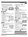
In channel mode, turn the selector knob to choose the channel.
1.
Hold
2.
key until the transceiver prompt a Du and channel number
display ashes.
Turn selector knob to choose channel number for storage. ( If the
3.
CHANNEL SCAN SKIP
CHANNEL EDIT
CHANNEL COPY
6
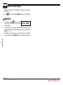
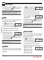
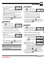
EMERGENCY ALARM
To start emergency alarm, hold the right volume knob until the trans
-ceiver displays ALARM and emit alarm. Re-power on the transceiver to
exit alarm. This transceiver has 4 kind of alarm which can be setup by
programming software.
6
for over 0.5 second, the radio prompts
"DU DU", and LCD displays "SKIP", and now
the current channel is Scan Skip.
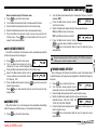
SCAN RANGE LIMIT
You can set the VFO scan frequency range by this function:
Choose upper limit and lower limit frequency, there are L1/U1- L5/
1.
U5, five couple of limit frequency for selection. L stands for lower
limit and U stands for the upper limit. the upper limit must over the
lower limit frequency. Please refer to the
Channel Edit to setup the limit frequency.
In VFO mode, set the VFO frequency in
2.
the range between upper and lower limit.
Press
3.
key to start scan in lmited range.
www.at-5888uv.com

15
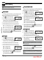
Shortcut Operations
In standby, hold
1.
key unti l th e
transceiver prompt DU, and channel
number ashes.
Turn selector knob to choose channel number for delete. (If the
2.
storage has data, the LCD will display the frequency, otherwise will
display"----------")
Hold Main band volume knob, until the transceiver emit DU DU
3.
prompt and LCD displays MEN-OUT, the channel delete completed.
CHANNEL DELETE
7
storage has data , the LCD will display the frequency, otherwise will
display"----------")
Press
4.
key, the LCD displays MEN-IN, channel copy completed.
6
www.at-5888uv.com
Page is loading ...
Page is loading ...
Page is loading ...
Page is loading ...
Page is loading ...
Page is loading ...
Page is loading ...
Page is loading ...
Page is loading ...
Page is loading ...
Page is loading ...
Page is loading ...
Page is loading ...
Page is loading ...
Page is loading ...
Page is loading ...
Page is loading ...
Page is loading ...
Page is loading ...
Page is loading ...
Page is loading ...
Page is loading ...
Page is loading ...
Page is loading ...
-
 1
1
-
 2
2
-
 3
3
-
 4
4
-
 5
5
-
 6
6
-
 7
7
-
 8
8
-
 9
9
-
 10
10
-
 11
11
-
 12
12
-
 13
13
-
 14
14
-
 15
15
-
 16
16
-
 17
17
-
 18
18
-
 19
19
-
 20
20
-
 21
21
-
 22
22
-
 23
23
-
 24
24
-
 25
25
-
 26
26
-
 27
27
-
 28
28
-
 29
29
-
 30
30
-
 31
31
-
 32
32
-
 33
33
-
 34
34
-
 35
35
-
 36
36
-
 37
37
-
 38
38
-
 39
39
-
 40
40
-
 41
41
-
 42
42
-
 43
43
-
 44
44


AnyTone Dual Band FM Transceiver User manual
- Category
- Car media receivers
- Type
- User manual
- This manual is also suitable for
Ask a question and I''ll find the answer in the document
Finding information in a document is now easier with AI
