
READ CAREFULLY.
KEEP THESE INSTRUCTIONS
.
Installation Over the Range
Instructions Microwave Oven
Read these instructions completely and carefully.
•
IMPORTANT –
Save these
instructions for local inspector’s use.
•
IMPORTANT –
Observe all
governing codes and ordinances.
•
Note to Installer –
Be sure to leave these
instructions with the Consumer.
BEFORE YOU BEGIN
• Note to Consumer – Keep these
instructions for future reference.
• Skill level
– Installation of this appliance requires
basic mechanical and electrical skills.
• Proper installation is the responsibility of the installer.
• Product failure due to improper installation is not
covered under the Warranty.
or
Questions? Call
1-800-944-9044(US)
1-800-265-8352(Canada)
January 2020
p/n A06823421
Page is loading ...

CONTENTS
General information
Important Safety Instructions .................................. 3
Electrical Requirements .......................................... 3
Damage – Shipment/Installation.............................. 4
Parts Included.......................................................... 4
Tools You Will Need ................................................ 5
Mounting Space ...................................................... 5
Step-by-step installation guide
6–8
Removing the Mounting Plate ...................... 6
Finding the Wall Studs .................................. 6
Determining Wall Plate Location .................. 7
Aligning the Wall Plate ................................ 8
Adapting Microwave Blower
B
Installation Instructions
Recirculating ...........................................
Mount the Microwave Oven ................19
Preparation of Top Cabinet ................17
Attach Mounting Plate to Wall ............17
Outside Back Exhaust..........................16
Outside Back Exhaust............................ 16–19
Placement of The Mounting Plate
......................
Preparing Rear Wall for
Remove Blower Plate ............................ 16..
Charcoal Filter
Installing or Change the
Preparation of Top Cabinet ...................
Check Blower Plate ...............................
..................................12-13
Attach Mounting Plate to Wall ...............
–
Installation Types............................................... .....9
for Outside Back Exhaust................17 18
–
Mount the Microwave Oven ............11
–
A
10 13
10
11
11
12
Outside Top Exhaust
Attach Mounting Plate to Wall............20
Preparation of Top Cabinet................21
Checking for Proper Damper
Connecting Ductwork..........................23
Adjust the Exhaust Adaptor ................23
Operation............................................22
Adapting Microwave Blower for
Outside top Exhaust
.................. 21-22
............................ 20-23
Mount the Microwave Oven
.........22-23
C
Before You Use Your Microwave .......................... 24
.......................... 2Template Information...................
Hood Exhaust
.................................................... 14-15
EN-2
5

This product requires a three-prong grounded outlet.
The installer must perform a ground continuity check
on the power outlet box before beginning the
installation to ensure that the outlet box is properly
grounded. If not properly grounded, or if the outlet
box does not meet electrical requirements noted
(under ELECTRICAL REQUIREMENTS), a qualified
electrician should be employed to correct any
deficiencies.
CAUTION: For personal
safety, remove house fuse
or open circuit breaker
before beginning
installation to avoid severe
or fatal shock injury.
CAUTION: For personal safety, the mounting surface
must be capable of supporting the cabinet load, in
addition to the added weight of this 63–85 pound
(28.5–38.5 kg) product, plus additional oven loads of
up to 50 pounds (22.7 kg) or a total weight of
113–135 pounds (51.3–61.2 kg).
CAUTION: For personal safety, this product cannot
be installed in cabinet arrangements such as an island or
a peninsula. It must be mounted to BOTH a top cabinet
AND a wall.
NOTE: For easier installation and personal safety, it is
recommended that two people install this product.
IMPORTANT – PLEASE READ CAREFULLY. FOR
PERSONAL SAFETY, THIS APPLIANCE MUST BE
PROPERLY GROUNDED TO AVOID SEVERE OR
FATAL SHOCK.
The power cord of this
appliance is equipped with a
three-prong (grounding)
plug which mates with a
standard three-prong
(grounding) wall receptacle
to minimize the possibility
of electric shock hazard
from this appliance.
You should have the wall receptacle and circuit checked
by a qualified electrician to make sure the receptacle is
properly grounded.
Where a standard two-prong wall receptacle is
encountered, it is very important to have it replaced
with a properly grounded three-prong wall receptacle,
installed by a qualified electrician.
DO NOT, UNDER ANY CIRCUMSTANCES, CUT,
DEFORM OR REMOVE ANY OF THE PRONGS
FROM THE POWER CORD. DO NOT USE WITH
AN EXTENSION CORD.
IMPORTANT SAFETY INSTRUCTIONS
Ensure proper
ground exists
before use
Installation Instructions
ELECTRICAL
REQUIREMENTS
Product rating is 120 volts AC, 60 Hertz, 15 amps and
1.6 kilowatts. This product must be connected to a
The power supply cord and plug should be brought to a
the prevailing local code for this kilowatt rating.
the requirements of the National Electrical Code or
voltage and frequency. Wire size must conform to
seperate and dedicated supply circuit of the proper
seperate and dedicated 15- to 20- ampere branch
National Electrical Code or the prevailing local code.
by a qualifed electrician and conform to the
The outler box and supply circuit should be installed
be located in the cabinet above the microwave oven.
circuit single grounded outlet. The outlet box should
EN-3

PART QUANTITY
Wood Screws 2
(
1
⁄4“ x 2“)
Toggle Bolts (and
wing nuts) (
3
⁄16“ x 3“)
Self-Aligning Machine 3
Screws (
1
⁄4“-28 x 3
1
⁄4“)
Nylon Grommet
(for metal cabinets)
1
• If the unit is damaged in shipment, return the
unit to the store in which it was bought for repair
or replacement.
• If the unit is damaged by the customer, repair or
replacement is the responsibility of the customer.
• If the unit is damaged by the installer (if other
than the customer), repair or replacement must
be made by arrangement between customer
and installer.
DAMAGE—SHIPMENT/
INSTALLATION
Installation Instructions
PARTS INCLUDED
You will find the installation hardware contained in
a packet with the unit. Check to make sure you have
all these parts.
NOTE: Some extra parts are included.
HARDWARE PACKET
PART
QUANTITY
Template
1
Template
Installation
1
Instructions
Separately
2
Packed
Filters
PARTS INCLUDED
(CONT.)
INSTALLATION
IN
STRUCTIONS
ADDITIONAL PARTS
1
adaptor
Grease
Exhaust
Glass
1
Tray
1
Ring
T ru ntable
CabinetTop
Rear
Wall
2
1
Use & Care
1
Shelf
1
1
USE & CARE
MANUAL
Manual
For some models
Convection
wire rack
For some models
EN-4

Installation Instructions
• Tape measure
• Hole saw
• Stud finder or hammer
• Level
• Duct and masking tape
• Scissors
• #1 Phillips screw driver
• Electric drill
• 3/16”, 1/2”, 5/8” drill bit
• Filler wood blocks for recessed
bottom cabinets
• Tin snips
Mounting Space
Tools you will need:
• The space between the cabinets must be 30" (76.2 cm) wide and free of obstructions.
• If you are going to vent your microwave oven to the outside, see Hood Exhaust Section for exhaust
duct preparation
• When installing the microwave oven beneath smooth, flat cabinets, be careful to follow the
instructions on the top cabinet template for power cord clearance.
• As a guide to installation, see page 26 for Mounting Template Information.
• If the cabinet depth, including the cabinet doors, is more than 13”, then the unit must be spaced out
from wall using adequate materials supporting 150 lbs to allow proper top vent air exhaust/intake.
66"
(167.6 cm)
or more from the
floor to the top of
the microwave
¼" Min
13" Max
(33 cm)
16 ½"
(41.9 cm)
Backsplash
30
30
(76.2 cm)
min.
(5.1 cm)
2"
Clearance
"(76.2 cm)
"
EN-5
Cabinet
Cabinet
(33 cm)
13" MAX.

PLACEMENT OF THE MOUNTING PLATE
1
Installation Instructions
Find the studs, using one of the following
methods:
A. Stud finder – a magnetic device which
locates nails.
B. Use a hammer to tap lightly across the
mounting surface to find a solid sound.
This will indicate a stud location.
After locating the stud(s), find the center by
probing the wall with a small nail to find the edges
of the stud. Then place a mark halfway between
the edges. The center of any adjacent studs should
be 16w (40.6 cm) or 24w (61 cm) from this mark.
Draw a line down the center of the studs.
THE MICROWAVE MUST BE CONNECTED TO
AT LEAST ONE WALL STUD.
1
Fold back all 4 carton flaps fully against carton
sides. Then carefully roll the oven and carton over
onto the top side. The oven should be resting in
the Styrofoam.
REMOVING THE MICROWAVE
OVEN FROM THE CARTON/
REMOVING THE MOUNTING
PLATE
FINDING THE WALL STUDS
B
.
A
.
2
Wall
Studs
Center
3
Carton
Pull the carton up and off the oven.
2
Styrofoam
3
1
Screws
Screws
Mounting Plate
5
4
Cut the middle of the outer protective plastic bag to
r
emove
the
ounting late
m
p
Remove the installation instructions,use and care,
exhaust adapter, turntable ring, shelf, filters, glass
Do not remove
the Styrofoam protecting the front of the oven.
Remove the screws from each end of the mounting
plate. This plate will be used as the rear wall template
ba
g.
and for mounting. Reinstall the screws into the holes
where they were removed.
tray and the small hardware
please note: Do Not Remove plastic plug
EN-6
protective cover until just before hanging the unit.
Filters and Turntable
Ring below glass tray
Exhaust Adapter
Small Hardware Bag
Glass Tray

DETERMINING WALL PLATE LOCATION UNDER YOUR CABINET
C.
Installation Instructions
Plate position flat bottom
cabinet
to Cooktop
C
3
/
8
"
T
O
E
D
G
E
N
OT
E
:
I
T
I
S
V
E
R
Y
IM
P
O
R
T
A
N
T
T
O
R
E
A
D
A
N
D
F
O
L
L
O
W
T
H
E
D
IR
E
C
T
I
O
N
S
IN
T
H
E
I
N
S
T
A
L
L
AT
I
ON
I
N
S
T
R
U
C
T
IO
N
S
B
E
F
O
R
E
P
R
O
C
EE
D
I
N
G
W
IT
H
T
H
IS
R
E
A
R
W
A
L
L
T
E
M
P
L
A
T
E
.
T
h
is
R
e
a
r
W
a
ll
T
e
m
p
l
a
t
e
s
e
r
v
e
s
t
o
p
o
s
it
io
n
t
h
e
b
o
t
t
o
m
m
o
u
n
t
i
n
g
p
l
a
t
e
a
n
d
t
o
l
o
c
a
t
e
t
h
e
h
o
ri
z
o
nt
a
l
e
x
h
a
u
s
t
o
u
t
le
t
.
1
.
U
s
e
a
l
e
v
e
l
t
o
c
h
e
c
k
t
h
a
t
t
h
e
t
e
m
p
la
t
e
is
p
o
s
it
io
n
e
d
a
c
c
u
ra
t
e
ly
.
2
.
L
o
c
a
t
e
a
n
d
m
a
r
k
a
t
le
a
s
t
o
n
e
s
t
u
d
o
n
t
h
e
le
f
t
o
r
ri
g
h
t
s
i
d
e
o
f
t
h
e
c
e
n
t
e
r
lin
e
.
I
t
is
i
m
p
o
rt
a
n
t
t
o
u
s
e
a
t
l
e
a
s
t
o
n
e
w
o
o
d
s
c
re
w
m
o
u
n
t
e
d
f
ir
m
ly
in
a
s
t
u
d
t
o
s
u
p
p
o
r
t
t
h
e
w
e
ig
h
t
o
f
t
h
e
m
i
c
r
o
wa
v
e
.
M
a
rk
t
w
o
a
d
d
i
t
i
o
n
a
l,
e
v
e
n
ly
s
p
a
c
e
d
lo
c
a
t
io
n
s
f
o
r
t
h
e
s
u
pp
lie
d
t
o
g
g
le
b
o
lt
s
.
3
.
D
r
il
l
h
o
le
s
in
t
h
e
m
a
r
k
e
d
lo
c
a
t
i
o
n
s
.
W
h
e
re
t
h
e
r
e
is
a
s
t
u
d
,
d
r
ill
a
3
/
1
6
"
h
o
le
f
o
r
w
o
o
d
s
c
re
w
s
.
F
o
r
h
o
le
s
t
h
a
t
d
o
n
o
t
li
n
e
u
p
w
i
t
h
a
s
t
u
d
,
d
ri
ll
5
/
8
"
h
o
le
s
f
o
r
t
o
g
g
le
b
o
lt
s
.
D
O
N
O
T
I
N
S
T
A
LL
T
H
E
M
O
U
N
T
I
N
G
P
L
A
T
E
A
T
T
H
I
S
T
I
M
E
.
4
.
R
e
m
o
v
e
t
h
e
t
e
m
p
la
t
e
f
ro
m
t
h
e
r
e
a
r
w
a
l
l.
5
.
R
e
v
i
e
w
t
h
e
I
n
s
t
a
lla
t
io
n
I
n
s
t
r
u
c
t
i
o
n
b
o
o
k
f
o
r
y
o
u
r
i
n
s
t
a
lla
t
io
n
s
i
t
u
a
t
io
n
.
L
o
c
a
t
e
a
n
d
m
a
r
k
h
o
l
e
s
to
a
l
i
g
n
w
i
t
h
h
o
l
e
s
i
n
t
he
mo
u
n
t
i
n
g
p
l
a
te
.
I
MP
O
R
T
A
N
T
:
LO
C
AT
E
A
T
L
E
A
S
T
ON
E
S
T
U
D
ON
E
I
T
H
E
R
S
I
D
E
O
F
T
H
E
CE
N
T
E
R
LIN
E
.
MA
R
K
T
H
E
L
OC
A
T
I
ON
F
O
R
2
A
D
D
IT
I
O
N
A
L
,
E
V
E
N
L
Y
S
P
A
C
E
D
T
O
G
G
L
E
B
OL
T
S
I
N
T
HE
M
O
U
N
T
IN
G
P
L
A
T
E
A
R
E
A
.
L
o
ca
te
a
n
d
ma
r
k
h
o
l
e
s
to
a
l
i
g
n
w
i
t
h
h
o
l
e
s
i
n
t
h
e
mo
u
n
t
i
n
g
p
l
a
t
e
.
I
MP
O
R
T
A
N
T
:
L
O
C
A
T
E
A
T
L
E
A
S
T
ON
E
S
T
U
D
O
N
E
I
T
H
E
R
S
I
D
E
O
F
T
H
E
C
E
N
T
E
R
L
IN
E
.
MA
R
K
T
H
E
L
OC
A
T
I
ON
F
O
R
2
A
D
D
I
T
I
ON
A
L
,
E
V
E
N
L
Y
S
P
A
C
E
D
T
O
GG
L
E
B
OL
T
S
I
N
T
H
E
M
O
U
N
T
IN
G
P
L
A
T
E
A
R
E
A
.
T
r
i
m
th
e
r
e
a
r
w
a
l
l
te
m
p
l
a
t
e
a
lo
n
g
t
h
e
d
o
tte
d
l
in
e
.
T
r
im
th
e
r
e
a
r
wa
l
l
te
m
p
l
a
te
a
lo
n
g
t
h
e
d
o
tte
d
l
in
e
.
1
2
"
4
"
D
a
r
le
v
u
e
lt
a
a
la
h
o
ja
p
a
ra
c
o
n
s
u
l
t
a
r
la
v
e
r
s
i
ó
n
e
n
E
s
p
a
ñ
o
l.
C
L
3/8
"
TO EDGE
N
O
TE
:
I
T
IS
VER
Y
IMPOR
T
AN
T T
O
R
EAD
AN
D
FO
L
LO
W
TH
E D
IR
EC
TI
O
N
S
I
N
T
H
E
I
N
ST
ALL
AT
IO
N
IN
ST
R
U
C
TI
O
N
S
B
EFO
R
E
PR
O
C
EED
IN
G
W
ITH
T
H
I
S
R
EAR
W
AL
L
T
EMPL
AT
E.
Th
is
R
e
a
r
W
a
ll
Te
mp
la
t
e s
er
v
e
s
to
p
o
s
it
i
o
n
th
e
b
o
t
to
m
mo
u
ntin
g
p
la
t
e
a
n
d
t
o l
o
c
at
e
th
e h
o
r
iz
on
ta
l e
x
h
a
us
t
ou
tle
t.
1
.
U
s
e
a
l
ev
e
l to
c
he
c
k
th
a
t
th
e
te
mp
la
t
e is
p
o
sitio
n
e
d
a
c
c
u
r
a
t
e
ly
.
2
.
L
o
c
a
te
a
n
d
ma
r
k
a
t le
a
s
t
o
n
e
s
t
u
d
o
n
t
he
le
ft
o
r
r
ig
ht
s
id
e
o
f
th
e c
e
n
te
r
l
in
e.
It
is
i
mp
o
r
ta
n
t t
o
u
s
e a
t le
a
s
t
o
n
e
w
o
o
d
s
c
r
e
w
mo
u
n
t
ed
f
ir
mly
in
a
s
tu
d
to
s
u
pp
o
r
t t
h
e
w
e
ig
h
t
o
f
th
e
mic
r
o
w
a
v
e
.
Ma
r
k
t
w
o
a
d
d
itio
na
l,
e
v
e
nl
y
s
p
a
ce
d
lo
c
a
tio
n
s
f
o
r
th
e
s
upp
li
e
d t
og
g
le
b
o
lts
.
3.
D
r
il
l h
ole
s
in
t
h
e
ma
r
k
e
d
lo
c
a
tio
n
s
.
W
h
e
r
e th
e
r
e
is
a
s
tu
d
, d
r
i
ll
a
3
/1
6"
h
o
le
fo
r
w
o
od
s
c
r
e
w
s
.
Fo
r
h
o
le
s
th
a
t d
o n
o
t lin
e
u
p
w
ith
a s
t
u
d
,
d
r
ill 5
/
8
" h
o
le
s fo
r
to
g
g
le
b
o
lts
.
D
O
N
O
T
IN
STA
L
L
TH
E
MO
U
N
TIN
G
P
L
ATE
AT TH
IS TIME
.
4
.
R
e
m
o
v
e
th
e
te
mp
la
te
fr
om
t
h
e
r
e
a
r
w
a
ll.
5
.
R
e
v
ie
w
t
he
In
s
ta
ll
atio
n
In
s
tru
c
t
io
n
bo
o
k fo
r
y
ou
r
in
sta
lla
tio
n
s
itu
a
tio
n.
Lo
cate an
d
ma
rk
h
ol
es t
o al
i
g
n w
ith
h
ol
e
s
i
n t
h
e
mo
unti
n
g
pl
a
t
e
.
I
M
PO
R
T
AN
T
:
LOC
A
TE AT
LEAST
ONE ST
U
D
ON
EI
TH
ER
SI
D
E
OF
TH
E C
EN
TER
LIN
E.
MAR
K
T
H
E
LOC
ATIO
N
FO
R
2
AD
D
I
T
I
ONAL
,
EVEN
L
Y
SPAC
ED
T
OG
GLE
BO
L
T
S
I
N
TH
E
MOUN
T
I
N
G
PLATE
AR
EA
.
Lo
cate
an
d
ma
rk
h
ol
es t
o al
i
g
n w
i
t
h
h
ol
e
s
in t
h
e
mo
un
tin
g pl
a
t
e
.
IMPO
R
T
AN
T:
LOC
AT
E AT
LEAS
T
ON
E ST
U
D
ON
EI
T
H
ER
SID
E
O
F
TH
E
C
EN
TE
R
LIN
E
.
MAR
K
T
H
E
LO
C
ATIO
N
F
O
R
2
AD
D
I
TI
ON
AL
, EVEN
L
Y
SPA
C
E
D
T
O
G
GLE
BO
L
T
S
I
N
TH
E
MO
U
N
TI
N
G
P
LAT
E
AR
EA.
Trim
th
e
r
e
ar
wall
t
em
p
lat
e
a
l
ong
th
e
d
otted
l
i
ne.
Trim
th
e
r
ear
wal
l
tem
pl
ate
a
l
ong
th
e
dotted
li
ne.
12
"
4"
D
arle
v
u
el
t
a
a
la
h
o
ja
p
a
r
a
c
o
n
s
u
lt
a
r
la
v
e
r
si
ó
n
e
n
E
sp
añ
o
l.
²
A
t
l
e
a
s
t
3
0
″
C
3/
8"
T
O
E
D
G
E
N
O
T
E
:
I
T
I
S
V
ER
Y
I
M
P
O
R
T
A
N
T
T
O
R
E
A
D
A
N
D
F
OL
LO
W
T
H
E
D
I
RE
C
T
I
O
N
S
I
N
T
H
E
I
N
S
TAL
L
A
T
I
O
N
I
N
S
T
RU
C
T
I
O
N
S
B
EF
O
R
E
P
R
OC
E
ED
I
N
G
W
I
T
H
T
H
I
S
R
E
A
R
W
A
LL
T
EM
P
LA
T
E
.
T
h
is
Re
a
r
W
a
l
l
T
e
m
p
l
a
t
e
se
r
v
e
s
t
o
p
o
s
i
tio
n
th
e
b
o
t
t
o
m
mo
u
n
t
i
n
g
p
l
a
t
e
a
n
d
t
o
l
o
c
a
te
th
e
h
o
r
iz
o
n
ta
l
e
x
h
a
u
st
o
u
tl
e
t
.
1
.
Us
e
a
le
v
e
l
to
c
h
e
c
k
t
h
a
t
t
h
e
te
mp
la
t
e
i
s
p
o
s
i
ti
o
n
e
d
a
c
c
u
r
a
t
e
ly.
2
.
L
o
c
a
te
a
n
d
ma
r
k
a
t
l
e
a
s
t
o
n
e
st
u
d
o
n
th
e
l
e
f
t
o
r
r
i
g
h
t
s
id
e
o
f
t
h
e
c
e
n
t
e
r
l
i
n
e
.
It i
s
i
mp
o
r
ta
n
t
t
o
u
se
a
t
le
a
s
t
o
n
e
wo
o
d
s
c
r
e
w
m
o
u
n
te
d
f
i
r
mly
in
a
s
t
u
d
t
o
s
u
p
p
o
r
t
t
h
e
we
ig
h
t
o
f
t
h
e
m
i
c
r
o
w
a
ve
.
Ma
r
k
tw
o
a
d
d
i
ti
o
n
a
l
, e
ve
n
l
y
s
p
a
c
e
d
lo
ca
t
io
n
s
f
o
r
t
h
e
s
u
p
p
l
i
e
d
t
o
g
g
l
e
b
o
l
t
s
.
3
.
D
r
i
l
l
h
o
l
e
s
in
t
h
e
m
a
r
k
e
d
lo
c
a
t
io
n
s
.
W
h
e
r
e
th
e
r
e
is
a
st
u
d
,
d
r
il
l
a
3
/
1
6
" h
o
l
e
f
o
r
wo
o
d
s
c
r
e
w
s.
F
o
r
h
o
le
s
t
h
a
t d
o
n
o
t lin
e
u
p
wi
t
h
a
stu
d
,
d
r
i
l
l
5
/
8
"
h
o
l
e
s
fo
r
t
o
g
g
l
e
b
o
l
t
s
.
DO N
O
T
I
N
ST
A
L
L
T
HE
M
OU
N
T
IN
G
P
L
A
T
E
AT
T
H
I
S
T
I
ME.
4
.
Re
mo
ve
t
h
e
t
e
m
p
la
t
e
fro
m
th
e
re
a
r
wa
l
l.
5
.
R
e
v
i
e
w t
h
e
I
n
s
t
a
lla
t
i
o
n
In
stru
c
t
i
o
n
b
o
o
k
fo
r
yo
u
r
i
n
sta
lla
t
io
n
situ
a
t
io
n
.
Lo
c
at
e
a
nd m
ar
k
h
oles
t
o
al
i
gn
w
ith
ho
les
i
n
t
h
e
m
o
u
nt
ing
pl
a
t
e
.
I
M
P
O
R
T
A
N
T
:
LO
C
AT
E
A
T
LE
A
ST
ON
E
S
T
UD
ON
E
I
T
H
E
R
S
I
DE
OF
T
H
E
C
E
N
T
E
R
LI
N
E
.
M
A
R
K
T
H
E
L
OC
A
T
I
O
N
F
OR
2
A
D
D
I
T
I
O
N
A
L,
E
V
EN
L
Y
S
P
A
C
ED
T
OG
G
L
E
B
OL
T
S
IN
T
H
E
M
OU
N
T
I
N
G
P
LA
T
E
A
R
E
A.
Lo
c
a
t
e
a
nd
m
ar
k
ho
le
s
t
o
align
w
i
t
h
ho
l
es
i
n
t
he
m
o
u
nt
i
ng
pl
a
t
e
.
I
M
P
O
R
T
A
N
T
:
LO
C
AT
E
AT
LEA
S
T
ON
E
S
T
U
D
O
N
E
I
T
H
ER
SI
D
E
O
F
T
H
E
C
E
N
T
E
R
LI
N
E
.
M
A
R
K
T
H
E
LO
C
A
T
I
O
N
F
OR
2
A
D
D
I
T
I
O
N
AL
,
E
V
E
NLY
S
P
A
C
ED
T
OGG
LE
B
OL
T
S
I
N
T
H
E
M
O
U
N
T
I
N
G
P
LA
TE
A
R
E
A.
T
r
i
m
t
h
e
r
e
a
r
w
al
l
t
e
m
p
l
a
t
e
al
o
n
g
t
h
e
d
o
t
ted
l
i
n
e.
T
r
i
m
t
h
e
r
e
ar
wal
l
t
e
m
p
l
a
t
e
a
l
o
n
g
t
h
e
d
o
tte
d
l
i
n
e
.
12"
4
"
D
a
r
le
v
u
e
lta
a
l
a
ho
j
a
pa
r
a
c
on
s
ul
t
ar
la
v
e
r
s
ió
n
e
n
E
s
p
a
ñ
ol
.
Your cabinets may have decorative trim that
interferes with the microwave installation. Remove
the decorative trim to install the microwave properly
and to make it level.
THE MICROWAVE MUST BE LEVEL.
Use a level to make sure the cabinet bottom is level.
If the cabinets have a front overhang only, with no
back or side frame, install the mounting plate down
the same distance as the front overhang depth. This
will keep the microwave level.
Measure the inside depth of the front overhang.
Draw a horizontal line on the back wall an equal
distance below the cabinet bottom as the inside
depth of the front overhang.
For this type of installation with front overhang
only, align the mounting tabs with this horizontal
line, not touching the cabinet bottom as described
in Step D.
Draw a vertical line on
the wall at the center of
the 30
″ wide space.
Tape the Rear Wall
Template onto the wall
matching the centerline
and touching the
bottom of the cabinet.
to Cooktop
Draw a vertical line on the wall at the center of the
30
″ space.
Tape the Rear Wall Template onto the wall
matching the centerline and touching the bottom
C
3/
8
"
TO
E
D
G
E
N
O
T
E
:
I
T
I
S
V
ER
Y
I
MP
O
RT
A
N
T
T
O
RE
A
D
A
ND
F
O
LL
O
W
T
HE
DI
RE
CT
I
O
NS
I
N
THE
INS
T
ALLA
TI
ON
I
N
S
T
RU
CT
I
ONS
BE
F
OR
E
P
R
O
C
E
E
D
I
N
G
W
I
T
H
T
H
I
S
RE
A
R
W
A
L
L
T
E
MP
L
A
TE
.
T
h
i
s
R
e
a
r
Wa
l
l
T
e
mp
l
a
t
e
se
r
ve
s to
p
o
si
t
i
o
n
the
b
o
t
t
o
m
mo
u
n
t
i
n
g
p
l
a
t
e
a
n
d
t
o
l
o
ca
t
e
t
h
e
h
o
r
i
z
o
n
t
a
l
e
xh
a
u
st
o
u
t
l
e
t
.
1
.
U
se
a
l
e
v
e
l
t
o
c
h
e
ck t
h
a
t
th
e
t
e
m
p
l
a
t
e
i
s
p
o
si
t
i
on
e
d
a
c
c
u
r
a
te
l
y.
2
.
L
oc
a
t
e
a
n
d
ma
r
k
a
t
l
e
a
st
o
n
e
stu
d
o
n
t
h
e
l
e
f
t
o
r
r
i
g
h
t
s
i
d
e
o
f
t
h
e
c
e
n
t
e
r
l
i
n
e
.
I
t
i
s
i
mp
o
r
ta
n
t t
o
u
se
a
t
l
e
a
s
t
o
n
e
w
o
o
d
sc
r
e
w
m
o
u
n
t
e
d
fi
r
ml
y
i
n
a
stu
d
t
o
su
p
p
o
r
t
t
h
e
we
i
g
h
t
o
f
th
e
m
i
c
r
o
w
a
v
e
.
M
a
r
k
t
w
o
a
d
d
i
t
i
o
n
a
l
,
e
ve
n
l
y
sp
a
ce
d
l
o
ca
t
i
o
n
s for
t
h
e
su
pp
l
i
e
d
tog
g
l
e
b
o
l
t
s
.
3
.
D
ri
l
l
h
o
l
e
s
i
n
t
h
e
m
a
r
ke
d
l
o
ca
t
io
n
s.
Wh
e
r
e
t
h
e
re
i
s
a
s
tu
d
,
d
r
i
l
l
a
3
/
1
6"
h
o
l
e
for
w
o
o
d
scr
e
w
s.
F
o
r
ho
l
e
s
t
h
a
t
d
o
n
o
t
l
i
n
e
u
p
w
i
t
h
a
st
u
d
,
d
r
i
l
l
5
/
8
" h
o
l
e
s
f
o
r
t
o
g
g
l
e
b
o
l
t
s
.
D
O
N
O
T
I
N
S
T
A
L
L
T
H
E
M
O
U
N
T
I
N
G
PL
A
T
E
AT
T
H
I
S T
I
M
E
.
4
.
R
e
m
o
ve
th
e
t
e
mp
l
a
t
e
f
r
o
m t
h
e
r
e
a
r
w
a
l
l.
5
.
R
e
v
i
e
w
the
I
n
sta
l
l
a
t
i
o
n
I
n
str
u
c
t
i
o
n
b
o
o
k f
o
r
yo
u
r
i
n
sta
l
l
a
t
i
o
n
si
t
u
a
t
i
o
n
.
Loc
at
e
and
ma
rk
h
ol
es
t
o
al
i
gn
w
i
t
h
h
o
l
e
s
i
n
t
he
mo
u
n
t
i
n
g
p
l
a
te.
I
MP
O
RT
A
N
T
:
L
O
CA
T
E
A
T
LE
A
S
T
ONE
S
T
UD
ON
E
I
T
HE
R
S
I
D
E
O
F
T
HE
CE
N
T
E
R
L
INE
.
MA
R
K
T
HE
L
OC
A
T
I
O
N
F
O
R
2
A
D
DI
T
I
O
NA
L,
E
VE
NL
Y
SP
A
CE
D
T
O
G
G
LE
B
OLT
S
I
N
TH
E
M
O
U
N
T
I
NG
P
L
A
T
E
A
R
E
A
.
L
oc
at
e
a
nd
ma
rk
h
ol
e
s
t
o
a
l
i
gn
w
i
t
h
ho
l
e
s
i
n
t
h
e
mo
un
t
i
n
g
p
l
a
t
e
.
IM
P
O
RT
A
NT
:
LOCA
T
E
A
T
LE
A
S
T
ON
E
S
T
UD
ON
EI
TH
E
R
S
I
D
E
O
F
T
H
E
CE
NT
E
R
L
I
NE
.
MA
RK
T
H
E
L
O
C
A
T
I
O
N
F
O
R
2
A
DD
I
T
I
O
NA
L
,
E
V
E
NL
Y
S
P
A
CE
D
T
O
G
G
LE
B
O
LT
S
I
N
THE
MOUN
T
ING
P
L
A
T
E
A
RE
A
.
T
r
i
m
t
h
e
rear
w
a
l
l
temp
l
ate
a
l
on
g
th
e
do
tt
e
d
l
i
n
e.
T
ri
m
t
h
e
rea
r
w
a
ll
temp
l
ate
a
l
on
g
t
h
e
do
tt
e
d
l
in
e
.
12"
4"
Da
rl
e
v
u
e
l
t
a
a
la
ho
ja
p
a
r
a
c
o
n
s
ult
a
r
la
v
e
r
s
ió
n
e
n
E
s
p
a
ñ
o
l
.
cabinet bottom
with front overhang
Plate position framed
recessed
Plate position
bottom
1
3
2
300″0
30
cabinet frame.
300″0
30
2″
16-1/2
-beneath
-beneath
-beneath recessed
cabinet
1/4"
Minimum
clearance
1/4"
Minimum
clearance
1/4"
Minimum
clearance
Draw a line on the
back wall equal to the
depth of the front
overhang.
1/4"
Minimum
clearance
EN-7

Installation Instructions
ALIGNING THE WALL PLATE
D.
Area E
Hole A
Hole B
Centerline
notches
Draw a Vertical Line
on Wall from Center
of Top Cabinet
Draw a horizontal line on wall at the
bottom of “Rear Wall Template”.
Horizontal Line
Horizontal Line
C
L
3/8" TO EDGE
%#76+10Ä+(':*#756#ਸ਼+5
215+6+10'&
1765+&'
4'%1//'0&'&&+/'05+
10)4'#5'Ä.#&'0#+49+..
&+5%*#4)'+061*175'5647%674'
/+0+/7/9+&6*4'37+4'&
4'#49#..6'/2.#6'
NOTE: IT IS VERY IMPORTANT TO
READ AND FOLLOW THE DI
RECTIONS
IN THE INSTALLATION INSTRUCTIONS
BEFORE PROCEEDI
NG WITH
THIS
REAR WALL TEMPLATE.
This Rear Wal
l Template serves t
o position the bottom
mounting plate and to locate
the horizontal exhaust
outlet.
1. Use a level to check th
at the template is positioned
accurately.
2. Locate and ma
rk at least one stud on the left or
right side of the centerlin
e.
016'
It is important to use at least one wood
screw mounted firmly in a stud to s
upport the weight
of the microwave. Mark two add
itional, evenly spaced
locations for the supp
lied toggle bolts.
3. Drill holes in the marked locatio
ns. Where there is
a stud, drill a 3/16" hole for
wood screws. For hole
s
that do not line up with a st
ud, drill 5/8" holes for
toggle bolts.
016'
DO NOT INSTALL THE M
OUNTING PLATE
AT THIS TIME.
4. Remove the tem
plate from the rear wall.
5. Review the Installation Instru
ction book for your
installation situation.
Locate and mark
holes to align with h
oles in the
mounting plat
e.
IMPORTANT:
LOCATE
AT LEAST ONE
STUD ON EITHER SIDE OF
THE CENTERLINE.
MARK THE LOCATION FOR 2
ADDITIONAL, EVENLY
SPACED
TOGGLE BOLTS IN
THE MOUNTING PLATE
AREA.
Locate and mark
holes to align with hol
es in the
mounting plat
e.
IMPORTANT:
LOCATE
AT LEAST ONE
STUD ON EITHER SIDE OF
THE CENTERLINE.
MARK THE LOCATION FOR 2
ADDITIONAL, EVENLY
SPACED
TOGGLE BOLTS IN
THE MOUNTING PLATE
AREA.
Trim the rear
wall template al
ong the dotted
line.
%
#
$
%
&
(%76176(14*14+<106#.
1765+&'':*#756
%76*1.'6*417)*
4'#49#..
(14':*#756#ਸ਼
12"
4"
Darle vuelta a la hoja para consultar la
versión en Español.
Draw a vertical line on the wall at the center of the
30" wide space.
NOTE: DO NOT MOUNT THE PLATE AT THIS
TIME.
NOTE: Holes A and B are inside area E. If neither of
important to have at least one wood screw mounted
firmly in a stud to support the weight of the
microwave. Set the mounting plate aside.
1
2
Draw a horizontal line on the wall at the bottom of
“Rear Wall Template”.
Holes A and B are not in a stud, find a stud somewhere
in area E and draw a circle to line up with the stud. It is
3
Find a wall stud in area "E" of mounting plate
Refer to section 1B. Finding the wall studs.
For attaching the mounting plate into stud drill
a 3/16" hole into wood stud. Drill a 5/8" hole for
toggle bolt in 1 other location (Hole A or Hole B)
4
EN-8

INSTALLATION TYPES
This microwave oven is designed for adaptation to
the following three types of ventilation:
B.Outside Back Exhaust (Horizontal Duct)
proceed to that section.
OUTSIDE TOP EXHAUST
(VERTICAL DUCT)
OUTSIDE BACK EXHAUST
(HORIZONTAL DUCT)
See page 20
Adaptor in Place for
Outside Top Exhaust
2
B
Adaptor Must Be
Moved to the Back for
Outside Back Exhaust
NOTE: This microwave is shipped assembled for
Recirculating. Select the
type of ventilation required
(Choose A, B or C)
for your installation and
Installation Instructions
outside. If you plan to recirculate the air back into the room, proceed to page 10.
A.Recirculating (Non-Vented Ductless)
C.Outside Top Exhaust (Vertical Duct)
C
RECIRCULATING
(NON-VENTED DUCTLESS)
recirculating exhaust.
disposable charcoal filter
installed to help remove
smoke and odors.
See page 10
Models are shipped for
Some mod els have a
A
EN-9
NOTE: Read the pages 14-15 only if you plan to vent your exhaust to the
See page 16

INSTALLATION OVERVIEW
Attach Mounting Plate to Wall
Prepare Top Cabinet
Mount the Microwave Oven
IMPORTANT NOTES:
• Make sure the screws for the blower motor and blower
plate are securely tightened when they are reinstalled.
This will help to prevent excessive vibration.
• Make sure the motor wiring has been properly routed
and secured, and that the wires are not pinched.
Installation Instructions
Place the mounting plate against the wall and
insert the toggle wings into the holes in the wall
to mount the plate.
NOTE: Before tightening toggle bolts and wood
screw, make sure the bott m of the mounting plate
touch the bottom of the cabinet when pushed flush
against the wall and that the plate is properly
centered under the cabinet.
CAUTION: Be careful to avoid pinching fingers
between the back of the mounting plate and the wall.
Tighten all bolts. Pull the plate away from the wall
to help tighten the bolts.
4
3
ATTACH THE MOUNTING
PLATE TO THE WALL
Attach the plate to the wall using toggle bolts.
At least one wood screw must be used to attach
the plate to a wall stud.
Remove the toggle wings from the bolts.
Insert the bolts into the mounting plate through
the holes designated to go into drywall and
reattach the toggle wings to
3
⁄4″ (19 mm) onto
each bolt.
1
Wall
Mounting
Plate
Spacing for Toggles
More Than Wall
Thickness
Bolt End
Toggle
Bolt
Toggle Wings
To use toggle bolts:
2
RECIRCULATING (Non-Vented Ductless)
Install or change Charcoal Filter
Check Blower Plate
NOTE:
If the cabinet depth including the cabinet doors
is more than 13""'' then the unit must be spaced
o
A
A1.
A2.
A3.
A4.
A5.
A1.
Cabinet
Cabinet
(33 cm)
13" MAX.
out from wall using adequate materials supporting
150 Ibs to allow proper top vent air exhaust/intake.
3
/
8"
TO
E
D
G
E
N
O
TE
:
I
T
IS
VE
RY
I
M
P
O
R
TA
NT
TO
RE
A
D AN
D FO
L
L
O
W
T
HE
D
I
RE
CT
IO
N
S
I
N
THE
I
NSTALLA
T
ION I
NS
TR
U
C
TI
O
N
S
B
E
F
O
RE P
R
O
CE
EDING
WITH
T
H
IS
RE
A
R W
A
LL
TEM
PL
A
T
E
.
T
hi
s
Re
a
r
Wa
ll
T
e
mp
l
a
te
s
e
r
ve
s
to p
o
s
itio
n
th
e
b
o
tto
m
mou
n
ti
n
g p
l
ate
and to
l
o
c
ate t
h
e h
o
r
i
z
on
ta
l
ex
h
au
s
t
ou
t
l
e
t.
1
. Us
e a le
vel
to
c
h
ec
k th
at th
e t
em
pla
te
is p
os
ition
ed
a
ccu
r
ate
l
y
.
2. L
oc
a
te a
nd
m
ar
k
a
t
l
e
a
s
t
o
ne
stu
d
on
t
h
e
le
ft or
r
i
g
h
t
s
id
e
o
f the
c
e
n
te
rl
i
n
e
.
It is im
po
r
t
an
t to u
s
e a
t l
e
as
t
one
wo
od
scr
e
w
mo
u
nte
d
fi
r
mly
i
n a
s
tud
to su
ppor
t th
e weigh
t
of
th
e m
i
c
r
o
w
ave
.
M
ar
k
tw
o
a
d
di
tion
a
l, e
ve
nly
sp
a
c
ed
l
o
c
atio
n
s f
or
th
e
s
uppl
ied
to
ggle
bo
l
t
s
.
3. Dr
i
ll
h
o
l
e
s in
th
e
m
ar
k
ed
lo
catio
n
s.
Whe
r
e
t
he
r
e is
a
s
tu
d
,
d
r
ill
a 3/
16
" h
ole
for
woo
d
s
c
r
e
w
s
.
F
o
r
h
oles
th
at
d
o
n
ot lin
e up
w
ith
a
s
tu
d, d
r
il
l 5
/8
"
h
o
le
s fo
r
to
gg
l
e bo
lts.
DO
NO
T
I
N
S
T
A
L
L T
HE
MO
U
NT
I
N
G
P
L
A
T
E
A
T
T
HIS
T
IM
E
.
4. Re
m
ove
th
e te
mp
la
te
fr
o
m
the
r
ea
r
wal
l.
5.
R
e
vie
h
t
w
e In
sta
llation
Ins
t
r
uc
ti
on b
oo
k fo
r
y
our
in
sta
ll
a
tio
n
s
i
tua
t
i
on.
Lo
c
at
e a
nd m
a
r
k
ho
les
to
ali
gn w
i
th holes
i
n
t
h
e
mounting
p
l
a
te.
IMPO
RT
ANT
:
LO
C
A
T
E
A
T L
EA
S
T
O
N
E
STU
D
O
N EI
T
HE
R
S
I
D
E
O
F
TH
E
CENTE
R
LIN
E
.
MAR
K
T
HE
LO
CATI
O
N
F
O
R 2 ADD
I
T
IO
N
A
L, EV
E
NL
Y
SP
A
CE
D T
O
G
GLE
BO
L
TS
I
N
THE MO
U
N
TING
PL
A
TE
A
REA
.
Locate an
d ma
r
k
hol
es
to al
i
gn
with holes
i
n
t
h
e
.
e
t
a
l
p
g
n
i
t
n
u
o
m
IMPO
RT
ANT
:
L
O
CA
T
E
A
T L
EA
S
T ON
E
ST
UD
O
N EI
T
HE
R
SI
D
E O
F
TH
E
CENT
E
R
L
I
N
E.
MA
RK
T
HE
L
O
C
AT
IO
N
FO
R
2
A
DDIT
ION
A
L
,
EV
EN
L
Y
SP
A
CED
TO
G
GL
E
BO
L
TS
I
N
TH
E MO
UN
TING
PLA
T
E
AR
EA
.
Tri
m t
he
r
ear
wal
l te
mp
l
a
t
e
a
long
t
he
do
t
ted
l
i
n
e
.
Trim t
he r
e
a
r
wal
l
t
em
pl
a
t
e a
long
t
h
e
d
ot
te
d
li
n
e.
12"
4"
Da
r
l
e
v
u
el
t
a
a
l
a
ho
j
a
pa
r
a
c
o
n
sul
t
a
r
l
a
v
e
r
s
i
ó
n
e
n
Es
pa
ño
l
.
EN-10

Installation Instructions
Attach the microwave oven to the top cabinet.
Cabinet Front
Cabinet Bottom Shelf
Filler Block
Microwave Oven Top
Equivalent to Depth
of Cabinet Recess
3
MOUNT THE MICROWAVE OVEN
FOR EASIER INSTALLATION AND PERSONAL
SAFETY, WE RECOMMEND THAT TWO PEOPLE
INSTALL THIS MICROWAVE OVEN.
NOTE: If your cabinet is metal, use the nylon
grommet around the power cord hole to prevent
cutting of the cord.
NOTE: We recommend using filler blocks if the
cabinet front hangs below the cabinet bottom shelf.
IMPORTANT: If filler blocks are not used,
case damage may occur from overtightening
screws.
Insert a self-aligning screw through top center
cabinet hole. Temporarily secure the oven by
turning the screw at least two full turns after the
threads have engaged. (It will be completely
tightened later.) Be sure to keep power cord
tight. Be careful not to pinch the cord, especially
when mounting flush to bottom of cabinet.
Self-Aligning Screw
4
2
Rotate front of oven
up against cabinet
bottom.
NOTE: When mounting the
microwave oven, thread
power cord through hole in
bottom of top cabinet. Keep
it tight throughout Steps
1–3. Do not pinch cord or
lift oven by pulling cord.
Lift microwave, tilt
it forward, and hook
slots at back bottom
edge onto four lower
tabs of mounting
plate.
1
CHECK BLOWER PLATE
Blower Plate
• Place the microwave in its upright position, with the
top of the unit facing up.
• Check to see that the blower plate is correctly
installed on the unit.
USE TOP CABINET TEMPLATE
FOR PREPARATION OF TOP
CABINET
• Read the instructions on the TOP CABINET
TEMPLATE.
• Tape it underneath the top cabinet.
• Drill the holes, following the instructions on the
TOP CABINET TEMPLATE.
CAUTION: Wear safety goggles when drilling holes
in the cabinet bottom.
You need to drill holes for the top support screws and
a hole large enough for the power cord to fit through.
Adjust top template accordingly if the microwave
is being spaced out from the wall due to cabinet depth
(including cabinet doors) of more th n 13"""''.
NOTE:
a
IMPORTANT: Do not grip or use the handle
or heat shield during installation. Do not
remove the cardboard spacers between the
heat shield and door.
A2.
A3.
A4.
EN-11

Installation Instructions
5
MOUNT THE MICROWAVE
OVEN (cont.)
8
7
Tighten the outer two screws to the top of the
microwave oven. (While tightening screws, hold
the microwave oven in place against the wall and
the top cabinet.)
Insert 2 self-aligning screws
through outer top cabinet
holes. Turn two full turns on
each screw.
packed with the microwave.
Install grease filters. See the Use &&&&and Care
INSTALLING OR CHANGE
THE CHARCOAL FILTER
(Some Models)
Unplug microwave oven or disconnect power.
NOTE: The charcoal filter is factory installed in some
models. Refer to the Use and Care to see if yours is
factory installed and for replacement information.
For models without the recirculation filter access
Open the microwave door and remove the two
vent mounting screws ;located on top of the
microwave using a #1 Phillips screwdriver.
Charcoal
Filter
Remove the charcoal filter by pushing the
top of the filter inwards,then pull it forward
out from the unit.
Slide the top of the new charcoal filter into the
top of the filter cavity.
door,follow these steps to replace or install a charcoal
filter.
A4.
A5.
A 5.1
A 5.2
A 5.3
A 5.4
EN-12

Installation Instructions
Close the microwave door. Plug in microwave
oven or reconnect power.
Reinstall the vent by sliding the bottom of the
vent into place. Push the vent top into position
and slide right into place. Replace the two vent
mounting screws located on top of the microwave
using a #1 Phillips screwdriver.
Press the bottom of charcoal filter to place it
into the correct position.
A5.
INSTALLING OR CHANGE
THE CHARCOAL FILTER(cont.)
A 5.5
A 5.6
A 5.7
EN-13

EQUIVALENT NUMBER EQUIVALENT
DUCT PIECES LENGTH x USED = LENGTH
Rectangular-to-Round 5 Ft. (1.5 m) x ( ) = Ft. or m
Transition Adaptor*
Wall Cap 40 Ft. (12.2 m) x ( ) = Ft. or m
90° Elbow 10 Ft. (3 m) x ( ) = Ft. or m
45° Elbow 5 Ft. (1.5 m) x ( ) = Ft. or m
90° Elbow 25 Ft. (7.6 m) x ( ) = Ft. or m
45° Elbow 5 Ft. (1.5 m) x ( ) = Ft. or m
Roof Cap 24 Ft. (7.3 m) x ( ) = Ft. or m
Straight Duct 6“ (15.2 cm) 1 Ft. (0.3 m) x ( ) = Ft. or m
Round or 3
1
⁄4“ x 10“
(8.2 x 25.4 cm Rectangular)
Total Ductwork = Ft. or m
Equivalent lengths of duct pieces are based on actual tests
and reflect requirements for good venting performance with
any vent hood.
* IMPORTANT: If a rectangular-to-round transition
adaptor is used, the bottom corners of the damper
will have to be cut to fit, using the tin snips, in order
to allow free movement of the damper
.
NOTE: If you need to install ducts, note that the total
duct length of 3
1
⁄4” x 10” (8.2 x 25.4 cm) rectangular or
” (15.2 cm) diameter round duct
Outside ventilation requires an EXTERNAL EXHAUST
NOTE: It is important that venting be installed using
the most direct route and with as few elbows as possible.
This ensures clear venting of exhaust and helps prevent
blockages. Also, make sure dampers swing freely and
nothing is blocking the ducts.
Exhaust connection:
The exhaust adaptor has been designed to mate with
a standard 3
1
⁄4” x 10” (8.2 x 25.4 cm) rectangular duct.
If a round duct is required, a rectangular-to-round
Maximum duct length:
For satisfactory air movement, the total duct length of
3
1
⁄4” x 10” (8.2 x 25.4 cm) rectangular or
6 ”(15.2 cm)
diameter round duct should not
exceed 140 equivalent
feet (42.7 m).
Elbows, transitions, wall and roof caps,
etc.,
present additional resistance to airflow and are
equivalent to a section of straight duct which is longer
than their actual physical size. When calculating the total
duct length, add the equivalent lengths of all transitions
and adaptors plus the length of all straight duct sections.
The chart below shows you how to calculate total
equivalent ductwork length using the approximate feet
of equivalent length of some typical ducts.
Installation Instructions
INSTALLATION INSTRUCTIONS FOR EXTERNAL EXHAUST DUCTING
DUCT.Read the following carefully.
(12.5”
should not exceed 140 equivalent feet (42.7 m).
diameter/ 6
(12.5”
diameter/
7 cm)
7 cm)
transition adaptor must be used.
diameter duct is acceptable to use.
"
A 5"""''''' " (12.7cm)/ 6" (15.2cm)
"
EN-14

EQUIVALENT NUMBER EQUIVALENT
DUCT PIECES LENGTH x USED = LENGTH
Roof Cap 24 Ft. (7.3 m) x (1) = 24 Ft. (7.3 m)
12 Ft. (3.6 m) Straight Duct 12 Ft. (3.6 m) x (1) = 12 Ft. (3.6 m)
(6”/15.2 cm Round)
Rectangular-to-Round 5 Ft. (1.5 m) x (1) = 5 Ft. (1.5 m)
Transition Adaptor*
Equivalent lengths of duct pieces are based on actual tests and
reflect requirements for good venting performance with any vent hood.
Total Length = 41 Ft. (12.5 m)
The following chart describes an example of one possible
ductwork installation.
OUTSIDE TOP EXHAUST (EXAMPLE ONLY)
NOTE: For back exhaust, care should be taken to align exhaust with space between studs, or wall should be prepared
at the time it is constructed by leaving enough space between the wall studs to accommodate exhaust.
* IMPORTANT: If a rectangular-to-round transition adaptor is used, the bottom corners of the damper
will have to be cut to fit, using the tin snips, in order to allow free movement of the damper.
The following chart describes an example of one possible
ductwork installation.
Installation Instructions
OUTSIDE BACK EXHAUST (EXAMPLE ONLY)
EQUIVALENT NUMBER EQUIVALENT
DUCT PIECES LENGTH* x USED = LENGTH
Wall Cap 40 Ft. (12.2 m) x (1) = 40 Ft. (12.2 m)
3 Ft. Straight Duct 3 Ft. (0.9 m) x (1) = 3 Ft. (0.9 m)
(3
1
⁄4” x 10”/8.2 x 25.4 cm
Rectangular)
90° Elbow 10 Ft. (3 m) x (2) = 20 Ft. (3 m)
Equivalent lengths of duct pieces are based on actual tests and
reflect requirements for good venting performance with any vent hood.
Total Length = 63 Ft. (19.2 m)
EXTERNAL EXHAUST DUCTING
EN-15

INSTALLATION OVERVIEW
B1. Prepare Rear Wall
B3. Attach Mounting Plate to Wall
B4. Prepare Top Cabinet
B5. Adjust Blower
B6. Mount the Microwave Oven
IMPORTANT NOTES:
• Make sure the screws for the
blower motor and blower plate
are securely tightened when
they are reinstalled. This will
help to prevent excessive
vibration.
•
been properly routed and secured,
and that the wires are not pinched.
Remove and save the screw that holds the blower
plate to the microwave. Lift off the blower plate.
Back of
Microwave
Installation Instructions
PREPARING THE REAR WALL
FOR OUTSIDE BACK EXHAUST
B1.
You need to cut an opening in the rear wall for
outside exhaust.
• Read the instructions on the REAR
WALL TEMPLATE.
• Tape it to the rear wall.
• Cut the opening, following the instructions of the
REAR WALL TEMPLATE.
B2.
OUTSIDE BACK EXHAUST (Horizontal Duct)
B
Blower Plate
REMOVE BLOWER PLATE
B2. Remove Blower Plate
3
/
8" T
O E
D
GE
NO
TE
: IT IS VE
RY IM
POR
T
AN
T
TO
RE
AD
A
ND
FOLL
OW
TH
E
DIR
EC
TIONS
IN T
HE IN
STA
L
LATIO
N
INS
TR
U
CTIO
NS
BEFO
RE
PR
OC
EED
ING
WITH
TH
I
S
RE
AR
W
ALL
TEMP
LA
TE
.
T
h
is
Re
ar
W
all
T
e
m
pl
a
t
e
s
erv
es
t
o
p
osit
i
on
t
h
e
bot
t
om
m
ount
ing
pla
t
e
a
nd
t
o
lo
c
a
t
e
t
he
h
or
i
z
o
nt
al
exhaust
ou
t
let
.
1.
Us
e
a
le
vel
t
o
check
t
hat
t
h
e
t
e
m
pla
t
e
is
posi
t
ione
d
accurat
ely.
2.
Loc
at
e
and
m
ark
a
t
l
ea
s
t
one
st
ud
on
t
he
l
ef
t
or
right
side
o
f
t
h
e
c
e
nt
er
l
ine.
I
t
is
im
port
ant
t
o
u
se
at
leas
t
on
e
woo
d
scr
e
w
m
oun
t
e
d
f
irmly
in
a
st
ud
t
o
s
up
port
t
he
wei
ght
of
t
h
e
m
i
crow
ave.
M
a
r
k
t
wo
a
ddit
ion
al
,
e
v
enly
spa
ced
loca
t
i
on
s
f
or
t
h
e
s
uppl
ied
t
og
g
le
bolt
s.
3.
Dr
i
ll
h
oles
in
t
h
e
m
ark
ed
l
oca
t
io
n
s.
Wh
ere
t
h
er
e
i
s
a st
ud,
dri
ll
a
3
/
1
6"
ho
le
f
o
r
wood
screws.
F
o
r
h
ol
es
t
hat
do
n
ot
li
ne
up
wit
h
a
st
u
d,
d
r
il
l
5
/
8
"
hole
s
f
or
t
oggle
b
olt
s
.
DO
NO
T
I
N
S
T
ALL
T
HE
M
O
UNT
I
NG
P
LAT
E
AT
T
HI
S
T
I
M
E.
4.
Rem
o
v
e
t
he
t
em
plat
e
f
rom
t
he
rear
wall.
5.
Review
t
h
e
I
nst
alla
t
io
n
I
n
s
truc
t
ion
boo
k
f
or
y
our
inst
allat
io
n
sit
u
a
t
io
n.
Lo
cate
and
mar
k hol
es to
a
lig
n w
ith ho
l
es
in the
mo
u
nti
ng p
late
.
IMP
O
RTA
NT:
LOCATE
AT LE
A
ST ON
E
STU
D
O
N
EITH
ER
S
ID
E
O
F
TH
E
C
E
NTER
LIN
E
.
M
A
R
K TH
E L
OC
AT
ION FOR
2 AD
D
IT
I
O
NAL
,
EVEN
LY
SP
ACE
D TOGG
LE BO
LTS IN
THE
MOU
NTIN
G
PLA
TE
AREA.
Lo
cate
and
mar
k hol
es to
a
lig
n w
ith h
o
les
in the
mo
unti
ng
p
late
.
IMPORTA
NT:
LO
CATE
AT LE
AST ON
E
STU
D O
N EIT
H
ER
SIDE
O
F
TH
E CE
N
TER
LIN
E.
MA
RK TH
E
L
OCAT
IO
N FOR
2 AD
DIT
I
O
NAL
, EVEN
LY
SP
AC
E
D
TOGG
LE
BO
LTS
IN
THE
M
OU
NTI
N
G PLA
TE
AR
EA.
Trim
the
r
ea
r wa
ll te
mpla
te a
l
o
n
g the d
otted
line
.
Tri
m
the
r
ea
r
wall
te
mpla
te
a
l
o
ng
the
d
otted
lin
e
.
1
2
"
4
"
Dar
le
vu
elta
a
la
ho
ja
pa
r
a
co
n
sul
tar
la
ve
r
sión
en
E
spañ
ol.
Make sure the motor wiring has
3
/
8
"
TO
EDG
E
NO
TE
:
I
T IS
V
ERY
I
M
PO
R
TANT TO
READ AND FO
LLO
W
T
HE
D
IRECTIO
N
S
IN THE
I
NSTALLAT
ION
INSTRU
CTI
O
N
S
BE
FO
RE PR
O
CEEDI
N
G
W
ITH
T
H
IS
REAR W
A
LL TE
M
PLA
T
E
.
T
h
is
R
e
a
r
Wall T
e
mp
l
a
te
s
e
r
ve
s
to
p
os
itio
n
th
e
b
o
tto
m
mou
ntin
g p
l
a
te
a
n
d
to l
o
c
ate th
e
h
o
r
i
z
on
ta
l
ex
h
au
s
t
ou
tle
t.
1
.
Us
e a l
e
vel
t
o
c
h
e
ck
th
at th
e t
emp
la
te
is p
os
ition
ed
a
ccur
a
te
ly
.
2.
L
o
c
a
t
e
a
nd
m
ar
k
a
t
le
a
s
t
o
ne
stu
d
on
th
e
le
ft o
r
r
igh
t
s
id
e
o
f
the
c
e
n
te
rl
i
n
e
.
I
t is im
p
o
rt
an
t
to u
s
e
a
t le
ast
o
ne
wo
od
scre
w
mo
u
nted
fi
r
mly
i
n a
s
tu
d
to
suppor
t
th
e
weigh
t
o
f
th
e mic
r
ow
ave.
M
ar
k
tw
o
a
d
d
i
tion
a
l, e
ve
nl
y
spa
c
e
d
lo
c
atio
n
s f
o
r
th
e
s
uppl
ied
to
ggle
bo
l
t
s.
3. D
ri
ll
h
ol
e
s
in
th
e m
a
r
k
ed lo
catio
n
s.
Whe
r
e t
h
e
r
e is
a
s
t
ud
,
d
r
ill
a
3/16" h
ol
e
for
woo
d
s
c
r
e
w
s
.
F
o
r
h
oles
th
at
d
o
n
ot
lin
e
up
w
ith
a
s
tu
d
, d
r
il
l 5
/
8
"
h
ole
s fo
r
to
gg
l
e
bo
lts
.
D
O
NO
T
I
N
S
T
A
L
L
T
H
E
MO
U
NT
I
N
G P
L
A
T
E
A
T
T
H
IS
T
IME.
4.
Re
m
ove th
e
t
e
mpla
t
e
fr
om
t
he
r
ea
r
wal
l.
5
.
R
e
vie
h
t
w
e
In
sta
llation
Ins
t
r
u
c
t
i
on b
oo
k f
or
y
ou
r
i
n
sta
lla
t
io
n
s
i
tua
t
ion.
Locat
e and m
ar
k
holes
to ali
gn wi
t
h
holes
i
n t
he
mountin
g
p
l
ate.
IM
PO
RTANT
:
LO
C
A
T
E
AT
LEA
S
T
O
N
E
S
TUD
ON E
I
T
HER
SIDE
O
F
TH
E
CENTER
LI
N
E
.
MARK
T
HE LOCATIO
N
F
OR 2 ADDIT
IO
N
A
L,
E
V
E
NLY
SP
ACE
D TO
G
GLE
BO
LTS
IN
THE MO
UN
TING
PLATE
AREA
.
Loc
at
e an
d
mar
k
hol
es
to al
i
gn with holes
in t
he
.
e
t
a
l
p
g
n
i
t
n
u
o
m
IMPO
RTANT
:
LO
CA
T
E AT LEA
S
T ON
E
ST
UD
O
N EI
T
HE
R
SI
D
E O
F
TH
E
CENT
E
R
LIN
E
.
MARK
T
HE LO
CA
TIO
N
F
O
R 2 ADDITION
A
L
, EV
EN
L
Y
SP
A
CE
D
T
O
G
GLE
BO
L
T
S IN
THE MO
UN
TING
PLATE
AR
E
A
.
T
rim t
he r
e
ar w
al
l
temp
lat
e
a
long
t
he
d
o
tted
line
.
Trim t
he rear
wa
l
l t
e
m
pla
t
e along
t
h
e dot
ted line
.
12"
4"
D
ar
l
e
v
u
e
lt
a
a
la
ho
j
a
p
a
r
a
c
o
ns
u
l
t
a
r
la
v
e
r
s
i
ón
e
n
Es
pa
ño
l
.
EN-16

ATTACH THE MOUNTING
PLATE TO THE WALL
B3.
•
Read the instructions on the TOP CABINET
TEMPLATE.
• Tape it underneath the top cabinet.
• Drill the holes, following the instructions on the
TOP CABINET TEMPLATE.
CAUTION: Wear safety goggles when drilling holes
in the cabinet bottom.
Wall
Mounting
Plate
Spacing for Toggles More
Than Wall Thickness
Toggle
Bolt
Toggle Wings
To use toggle bolts:
Bolt End
Installation Instructions
Attach the plate to the wall using toggle bolts.
At least one wood screw must be used to attach
the plate to a wall stud.
Remove the toggle wings from the bolts.
Insert the bolts into the mounting plate through
the holes designated to go into drywall and reattach
the toggle wings to
3
⁄4″ (19 mm) onto each bolt.
1
2
Place the mounting plate against the wall and
insert the toggle wings into the holes in the wall
to mount the plate.
NOTE: Before tightening toggle bolts and wood
screw, make sure the bottom of the mounting plate
touch the bottom of the cabinet when pushed flush
against the wall and that the plate is properly
centered under the cabinet.
CAUTION: Be careful to avoid pinching fingers
between the back of the mounting plate and the wall.
Tighten all bolts. Pull the plate away from the wall
to help tighten the bolts.
3
4
2
1
Remove and save screw that holds blower motor
to microwave.
ADAPTING MICROWAVE
BLOWER FOR OUTSIDE
BACK EXHAUST
B5.
End B
End A
will extend far enough to allow you to adjust
the blower unit.
Back of
Microwave
Blower Motor
Blower Motor
Screw
Forward
Openings Facing
Carefully pull out the blower unit. The wires
Before: Fan Blade
USE TOP CABINET TEMPLATE
FOR PREPARATION OF TOP
CABINET
B4.
You need to drill holes for the top support screws and
a hole large enough for the power cord to fit through.
Back of
Microwave
Roll the blower unit 90°
Back of
Microwave
3
Before Rotation After Rotation
EN-17

Attach the exhaust adaptor to the rear of the
oven by sliding it into the guides at the top
center of the back of the oven.
AFTER: Fan Blade
Openings Facing Back
Place the blower unit back into the opening.
Replace the blower plate in the same position
as before with the screw. Make sure the screw
is tight.
Roll the blower unit 90° so that fan blade
openings are facing out the back of the
microwave.
ADAPTING MICROWAVE
BLOWER FOR OUTSIDE
BACK EXHAUST (cont.)
B5.
Rotate blower unit counterclockwise 180°.
Before Rotation After Rotation
Gently remove the wires from the grooves.
Reroute the wires through grooves on other side
of the blower unit.
Before Rerouting After Rerouting
Wires Routed Through Right Side
Wires Routed Through Left Side
Back of
Microwave
Back of
Microwave
Blower Plate
Blower Motor
Screw
Secure the blower unit to the microwave with
the original screw.
Before Rolling After Rolling
Back of
Microwave
End A
End B
Back of
Microwave
Back of
Microwave
CAUTION: Do not pull or stretch the blower
unit wiring. Make sure the wires are not
pinched, and that they are properly secured.
NOTE: The blower unit exhaust
openings should match exhaust
openings on rear of microwave oven.
Installation Instructions
Push in securely until it is in the lower locking
tabs. Take care to assure that the damper hinge
is installed so that it is at the top and that the
damper swings freely.
Guide
Guide
Adaptor
Locking Tabs
Back of
Microwave
4
5
6
11
Back of mircrowave
Knockout Plates:
Snip all 4 webs on
each knockout panel
and remove the metal
knockouts for rear airflow.
Please take care to
remove any sharp edges
created from removing
the knockout plates.
7
8
9
10
with snips. (For some models)
Remove the knockout plates in the back of the unit
EN-18

Attach the microwave oven to the top cabinet.
Installation Instructions
3
MOUNT THE MICROWAVE
OVEN
B6.
FOR EASIER INSTALLATION AND PERSONAL
SAFETY, WE RECOMMEND THAT TWO PEOPLE
INSTALL THIS MICROWAVE OVEN.
NOTE: If your cabinet is metal, use the nylon
grommet around the power cord hole to prevent
cutting of the cord.
NOTE: We recommend using filler blocks if the
cabinet front hangs below the cabinet bottom shelf.
IMPORTANT: If filler blocks are not
used, case damage may occur from
overtightening screws.
Insert a self-aligning screw through top center
cabinet hole. Temporarily secure the oven by
turning the screw at least two full turns after the
threads have engaged. (It will be completely
tightened later.) Be sure to keep power cord
tight. Be careful not to pinch the cord, especially
when mounting flush to bottom of cabinet.
8
7
5
Cabinet Front
Cabinet Bottom Shelf
Tighten the outer two screws to the top of the
microwave oven. (While tightening screws, hold
the microwave oven in place against the wall and
the top cabinet.)
Filler Block
Microwave Oven Top
Equivalent
to Depth
of Cabinet
Recess
Insert 2 self-aligning screws
through outer top cabinet
holes. Turn two full turns on
each screw.
packed with the microwave.
Self-Aligning Screw
4
2
Rotate front of oven
up against cabinet
bottom.
NOTE: When mounting the
microwave oven, thread
power cord through hole in
bottom of top cabinet. Keep
it tight throughout Steps
1–3. Do not pinch cord or
lift oven by pulling cord.
Lift microwave, tilt it
forward, and hook
slots at back bottom
edge onto four lower
tabs of mounting
plate.
1
Tighten center
screw completely.
Install grease filters. See the Use &&&&and Care
IMPORTANT: Remove the cardhoard spacers between
heat shield and door.
IMPORTANT: Do not grip or use the handle
or heat shield during installation. Do not
remove the cardboard spacers between the
heat shield and door.
6
EN-19

Place the mounting plate against the wall and
insert the toggle wings into the holes in the wall
to mount the plate.
NOTE: Before tightening toggle bolts and wood
screw, make sure the bottom of the mounting plate
touch the bottom of the cabinet when pushed
flush against the wall and that the plate is properly
centered under the cabinet.
CAUTION: Be careful to avoid pinching fingers
between the back of the mounting plate and the wall.
Tighten all bolts. Pull the plate away from the wall
to help tighten the bolts.
3
4
ATTACH THE MOUNTING
PLATE TO THE WALL
Attach the plate to the wall using toggle bolts.
At least one wood screw must be used to attach
the plate to a wall stud.
Remove the toggle wings from the bolts.
Insert the bolts into the mounting plate
through the holes designated to go into drywall
and reattach the toggle wings to
3
⁄4″ (19 mm) onto
each bolt.
1
INSTALLATION OVERVIEW
Attach Mounting Plate to Wall
Prepare Top Cabinet
Mount Microwave Oven
Adjust Exhaust Adaptor
Wall
Mounting
Plate
Spacing for Toggles
More Than Wall
Thickness
Bolt End
Toggle
Bolt
Toggle Wings
To use toggle bolts:
Installation Instructions
2
OUTSIDE TOP EXHAUST (Vertical Duct)
IMPORTANT NOTES:
• Make sure the screws for the
blower motor and blower plate
are securely tightened when
they are reinstalled. This will
help to prevent excessive
vibration.
• Make sure the motor wiring has
been properly routed and secured,
and that the wires are not pinched.
. Connect Ductwork
Check Damper Operation
Adapting Microwave Blower for
Outside Top Exhaust
C
C2.
C1.
C3.
C4.
C6.
C5.
C7
C1.
3/
8"
TO
EDG
E
NOTE
:
IT
I
S
VERY
I
MPO
R
TANT TO
READ AND FO
LLO
W
T
HE
D
IRECTIO
N
S
IN THE INSTALLAT
ION INSTRU
CTI
O
N
S
BE
F
O
RE PR
O
CEEDING
WITH
T
H
IS
REAR W
A
LL TEM
PLA
TE.
Th
i
s
R
ea
r
W
a
ll
Templ
a
te
s
e
r
v
es to
p
o
s
itio
n
th
e b
o
tto
m
mou
ntin
g
p
l
a
te
a
nd
to l
oc
at
e
th
e ho
r
i
z
on
ta
l
exh
au
s
t
ou
t
let.
1
. Us
e
a l
e
v
el
to
c
h
ec
k
th
a
t the
t
e
m
pla
te
i
s
p
o
s
itione
d
a
c
cu
r
a
te
ly
.
2. L
o
c
at
e
a
nd
ma
r
k
a
t lea
s
t o
ne
s
tu
d
on th
e
le
ft o
r
r
ight
s
i
d
e
o
f the ce
n
te
rl
i
n
e
.
It
is i
mpo
r
t
a
n
t to
u
s
e
a
t le
as
t
one
wo
od
s
c
re
w
mo
unted
fi
r
mly
i
n
a
s
tud
t
o
s
upp
or
t
th
e w
ei
g
ht
of
th
e mic
r
o
w
av
e
.
M
a
r
k
t
w
o
a
d
di
ti
on
a
l, ev
en
ly
s
pa
c
ed
lo
c
a
ti
o
n
s
f
o
r
th
e
s
uppl
ied to
g
gle bol
t
s
.
3.
Dr
i
ll
h
ol
e
s
in
th
e
m
a
r
k
e
d lo
c
atio
n
s
.
Wher
e t
h
er
e
is
a s
tu
d
,
d
r
i
l
l
a 3/1
6"
h
ol
e
fo
r
woo
d sc
r
ew
s
.
F
o
r
h
o
les
th
at
do
n
o
t
l
in
e up
w
i
th
a
s
tu
d,
d
r
i
l
l
5
/8
"
h
o
l
e
s
fo
r
to
gg
l
e bo
lt
s
.
D
O
NOT
I
N
S
T
AL
L
T
H
E
M
O
U
NTI
N
G
P
L
AT
E
A
T
THIS
T
IM
E.
4
. Re
m
o
v
e
th
e
te
m
plate
fr
o
m
the
r
ea
r
wa
l
l.
5.
R
e
v
ie
wth
e In
s
ta
l
l
a
ti
on
Inst
r
ucti
o
n bo
ok
for
y
ou
r
i
n
s
ta
l
l
a
ti
o
n
s
i
tua
t
i
on
.
Locat
e
and m
ar
k
hole
s
t
o
ali
gn w
ith hol
es
in t
he
mounting
p
l
ate.
IM
P
O
RTANT
:
LO
C
A
T
E
AT
LEA
ST
O
NE
STUD
ON EI
T
HER
S
I
D
E
O
F
TH
E
CENT
E
R
LI
N
E
.
MARK
T
HE L
O
CATION
F
O
R 2 ADDIT
IO
N
A
L, EV
E
NL
Y
SP
ACE
D T
O
GGLE
BO
LTS
IN
T
HE MO
UN
TING
PLATE
AREA
.
Locate and mar
k
h
oles
to al
i
gn w
i
th
holes
in t
he
mounting
pla
te.
IMP
ORTANT
:
LO
C
A
T
E
AT LEA
ST O
N
E
STUD
O
N EI
THER SI
D
E
O
F
TH
E
CEN
T
E
R
LI
N
E
.
MARK
T
HE LO
CATIO
N
F
OR 2 ADDITION
A
L, EV
ENL
Y
SP
ACED
TOG
GLE BO
LT
S I
N
THE MO
UN
TING
PLATE
AREA.
Trim
t
he r
e
ar
w
al
l
tem
plat
e along
the do
tt
ed
line.
Trim the rear
w
al
l tem
pla
t
e along
t
he dotted lin
e.
12"
4"
Da
r
l
e
v
u
e
lt
a
a
la
ho
j
a
pa
r
a
c
o
n
s
u
lta
r
la
v
e
r
s
ió
n
e
n
E
s
pa
ño
l.
EN-20
Page is loading ...
Page is loading ...
Page is loading ...
Page is loading ...
Page is loading ...
Page is loading ...
Page is loading ...
Page is loading ...
Page is loading ...
Page is loading ...
Page is loading ...
Page is loading ...
Page is loading ...
Page is loading ...
Page is loading ...
Page is loading ...
Page is loading ...
Page is loading ...
Page is loading ...
Page is loading ...
Page is loading ...
Page is loading ...
Page is loading ...
Page is loading ...
Page is loading ...
Page is loading ...
Page is loading ...
Page is loading ...
Page is loading ...
Page is loading ...
Page is loading ...
Page is loading ...
Page is loading ...
Page is loading ...
Page is loading ...
Page is loading ...
Page is loading ...
Page is loading ...
Page is loading ...
Page is loading ...
Page is loading ...
Page is loading ...
Page is loading ...
Page is loading ...
Page is loading ...
Page is loading ...
Page is loading ...
Page is loading ...
Page is loading ...
Page is loading ...
Page is loading ...
Page is loading ...
Page is loading ...
Page is loading ...
Page is loading ...
Page is loading ...
Page is loading ...
Page is loading ...
Page is loading ...
-
 1
1
-
 2
2
-
 3
3
-
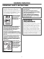 4
4
-
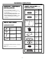 5
5
-
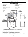 6
6
-
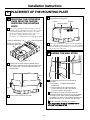 7
7
-
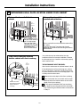 8
8
-
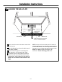 9
9
-
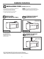 10
10
-
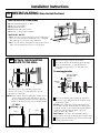 11
11
-
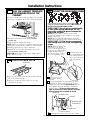 12
12
-
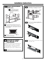 13
13
-
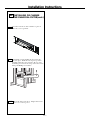 14
14
-
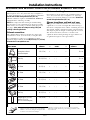 15
15
-
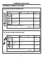 16
16
-
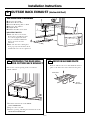 17
17
-
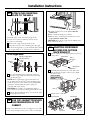 18
18
-
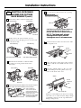 19
19
-
 20
20
-
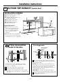 21
21
-
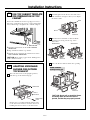 22
22
-
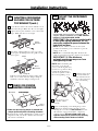 23
23
-
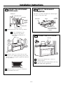 24
24
-
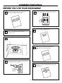 25
25
-
 26
26
-
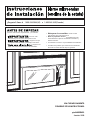 27
27
-
 28
28
-
 29
29
-
 30
30
-
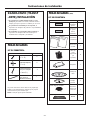 31
31
-
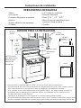 32
32
-
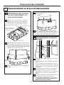 33
33
-
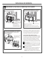 34
34
-
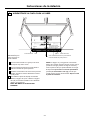 35
35
-
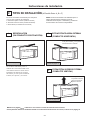 36
36
-
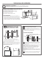 37
37
-
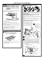 38
38
-
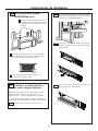 39
39
-
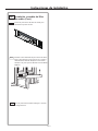 40
40
-
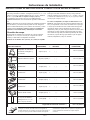 41
41
-
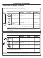 42
42
-
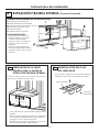 43
43
-
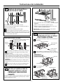 44
44
-
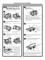 45
45
-
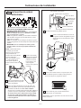 46
46
-
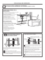 47
47
-
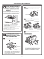 48
48
-
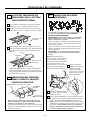 49
49
-
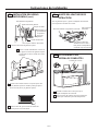 50
50
-
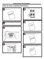 51
51
-
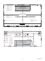 52
52
-
 53
53
-
 54
54
-
 55
55
-
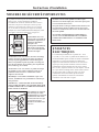 56
56
-
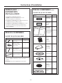 57
57
-
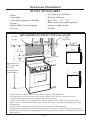 58
58
-
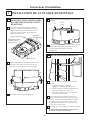 59
59
-
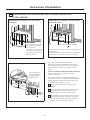 60
60
-
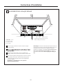 61
61
-
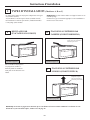 62
62
-
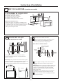 63
63
-
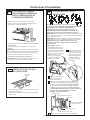 64
64
-
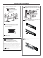 65
65
-
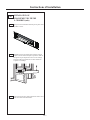 66
66
-
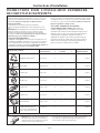 67
67
-
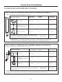 68
68
-
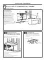 69
69
-
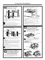 70
70
-
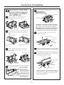 71
71
-
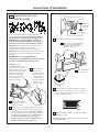 72
72
-
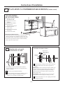 73
73
-
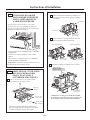 74
74
-
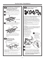 75
75
-
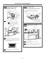 76
76
-
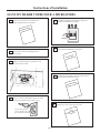 77
77
-
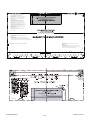 78
78
-
 79
79
-
 80
80


Ask a question and I''ll find the answer in the document
Finding information in a document is now easier with AI
in other languages
- français: Frigidaire 1797134 Guide d'installation
- español: Frigidaire 1797134 Guía de instalación
Related papers
-
Frigidaire FGBM19WNVF Installation guide
-
Frigidaire 1797324 Installation guide
-
-
-
Frigidaire FFMV1645TD Installation guide
-
Electrolux FPBM3077RF Owner's manual
-
Electrolux EI24MO45IB Installation guide
-
-