V-CYMBAL RIDE CY-13R
V-CYMBAL CRASH CY-12C
Owner’s Manual
* 5 1 0 0 0 6 0 9 6 4 - 0 1 *
Before using this unit, carefully read the sections entitled: “USING THE UNIT SAFELY” and “IMPORTANT NOTES”
(p. 2; p. 3). These sections provide important information concerning the proper operation of the unit. Additionally, in
order to feel assured that you have gained a good grasp of every feature provided by your new unit, Owner’s manual
should be read in its entirety. The manual should be saved and kept on hand as a convenient reference.

2
USING THE UNIT SAFELY
Used for instructions intended to alert the
user to the risk of injury or material
damage should the unit be used
improperly.
* Material damage refers to damage or
other adverse eects caused with
respect to the home and all its
furnishings, as well to domestic animals
or pets.
Used for instructions intended to alert the
user to the risk of death or severe injury
should the unit be used improperly.
The symbol alerts the user to things that must be
carried out. The specic thing that must be done is
indicated by the design contained within the circle. In the
case of the symbol at left, it means that the power-cord
plug must be unplugged from the outlet.
The symbol alerts the user to important instructions or
warnings.The specic meaning of the symbol is
determined by the design contained within the triangle. In
the case of the symbol at left, it is used for general
cautions, warnings, or alerts to danger.
The symbol alerts the user to items that must never be
carried out (are forbidden). The specic thing that must
not be done is indicated by the design contained within
the circle. In the case of the symbol at left, it means that
the unit must never be disassembled.
About WARNING and CAUTION Notices
About the Symbols
ALWAYS OBSERVE THE FOLLOWING
WARNING
• Do not open or perform any
internal modications on the
unit.
• Do not attempt to repair the
unit, or replace parts within
it (except when this manual
provides specic instructions
directing you to do so). Refer all servicing
to your retailer, the nearest Roland
Service Center, or an authorized Roland
distributor, as listed on the “Information”
page.
• Never install the unit in any of
the following locations.
6 Subject to temperature
extremes (e.g., direct
sunlight in an enclosed
vehicle, near a heating duct,
on top of heat-generating
equipment); or are
6 Damp (e.g., baths, washrooms, on wet
oors); or are
6 Exposed to steam or smoke; or are
6 Subject to salt exposure; or are
6 Humid; or are
6 Exposed to rain; or are
6 Dusty or sandy; or are
6 Subject to high levels of vibration and
shakiness.
• This unit should be used only
with a stand (MDS series) that is
recommended by Roland.
• When using the unit
with a stand (MDS series)
recommended by Roland, the
stand (MDS series) must be
carefully placed so it is level and sure to
remain stable. If not using a stand (MDS
series), you still need to make sure that
any location you choose for placing the
unit provides a level surface that will
properly support the unit, and keep it from
wobbling.
WARNING
• Never allow foreign objects
(e.g., ammable objects, coins,
wires) or liquids (e.g., water
or juice) to enter this product.
Doing so may cause short
circuits, faulty operation, or
other malfunctions.
• In households with small
children, an adult should
provide supervision until the
child is capable of following all
the rules essential for the safe operation
of the unit.
• Protect the unit from strong
impact.
(Do not drop it!)
CAUTION
• Try to prevent cords and cables
from becoming entangled. Also,
all cords and cables should be
placed so they are out of the
reach of children.
• Never climb on top of, nor place
heavy objects on the unit.
• Should you remove the stopper
bolt, keep them in a safe place
out of children’s reach, so there
is no chance of them being
swallowed accidentally.

3
IMPORTANT NOTES
Placement
6 Do not expose the unit to direct sunlight, place it near devices
that radiate heat, leave it inside an enclosed vehicle, or otherwise
subject it to temperature extremes. Excessive heat can deform or
discolor the unit.
6 When moved from one location to another where the
temperature and/or humidity is very dierent, water droplets
(condensation) may form inside the unit. Damage or malfunction
may result if you attempt to use the unit in this condition.
Therefore, before using the unit, you must allow it to stand for
several hours, until the condensation has completely evaporated.
6 Do not allow rubber, vinyl, or similar materials to remain on
this unit for long periods of time. Such objects can discolor or
otherwise harmfully aect the nish.
Maintenance
6 For everyday cleaning wipe the unit with a soft, dry cloth or one
that has been slightly dampened with water. To remove stubborn
dirt, use a cloth impregnated with a mild, non-abrasive detergent.
Afterwards, be sure to wipe the unit thoroughly with a soft, dry
cloth.
6 Never use benzine, thinners, alcohol or solvents of any kind, to
avoid the possibility of discoloration and/or deformation.
Additional Precautions
6 Use a reasonable amount of care when using the output jacks.
Rough handling can lead to malfunctions.
6 When connecting / disconnecting all cables, grasp the connector
itself—never pull on the cable. This way you will avoid causing
shorts, or damage to the cable’s internal elements.
6 To avoid disturbing your neighbors, try to keep the unit’s volume
at reasonable levels. You may prefer to use headphones, so you do
not need to be concerned about those around you.
6 This instrument is designed to minimize the extraneous sounds
produced when it’s played. However, since sound vibrations
can be transmitted through oors and walls to a greater degree
than expected, take care not to allow these sounds to become a
nuisance to neighbors, especially when using headphones.
6 When you need to transport the unit, package it in the box
(including padding) that it came in, if possible. Otherwise, you will
need to use equivalent packaging materials.
6 The rubber portion of the striking surface is treated with a
preservative to maintain its performance. With the passage of
time, this preservative may appear on the surface as a white stain,
or reveal how the pads were struck during product testing. This
does not aect the performance or functionality of the product,
and you may continue using it with condence.
6 Continuous playing may cause dis-coloration of the pad, but this
will not aect the Pad’s function.
6 Roland,V-Drums, and V-CYMBALS are registered trademarks of
Roland Corporation in the United States and/or other countries.
Copyright © 2017 ROLAND CORPORATION
• All product names mentioned in this document are trademarks or
registered trademarks of their respective owners.

4
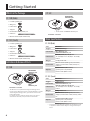
Getting Started
What’s in the Package
CY-13R (Ride)
5 CY-13R Cymbal pad
5 Wing nut
5 Felt washer
5 Stopper
5 Connection cable (stereo) x 2
5 Cable tie
5 Owner’s manual (this document)
CY-12C (Crash)
5 CY-12C Cymbal pad
5 Wing nut
5 Felt washer
5 Stopper
5 Connection cable (stereo)
5 Cable tie
5 Owner’s manual (this document)
Denitions & Names of Parts
CY-13R
Bow
Edge
Bell
BOW/EDGE
OUTPUT jack
BELL
OUTPUT jack
Diameter: 13 inches
* The CY-13R is not capable of detecting the striking position.
If you’re using a Roland percussion sound module that is capable
of detecting the striking position, you’ll need to set the ride’s
Position Ctrl to OFF.
For details on how to make the setting, refer to the owner’s
manual that came with your percussion sound module.
CY-12C
BOW/EDGE
OUTPUT jack
Diameter: 12 inches
Bow
Edge
* The CY-12C has no BOW/BELL OUTPUT jack.
Main Specications
CY-13R (Ride)
Size 13 inches
Trigger 3 (Bow/Bell/Edge)
Connectors
BELL OUTPUT jack,
BOW/EDGE OUTPUT jack
Dimensions
331 (W) x 331 (D) x 48 (H) mm
13-1/16 (W) x 13-1/16 (D) x 1-15/16 (H)
inches
Weight 1.1 kg / 2 lbs 7 oz
Accessories
Owner’s manual, Wing nut, Felt washer,
Stopper, Connection cable (stereo) x 2,
Cable tie
Options
Cymbal mount (MDY series)
Cymbal parts set (CYM-10)
Drum stands (MDS series)
CY-12C (Crash)
Size 12 inches
Trigger 2 (Bow/Edge)
Connectors BOW/EDGE OUTPUT jack
Dimensions
305 (W) x 305 (D) x 45 (H) mm
12-1/16 (W) x 12-1/16 (D) x 1-13/16 (H)
inches
Weight 940 g / 2 lbs 2 oz
Accessories
Owner’s manual, Wing nut, Felt washer,
Stopper, Connection cable (stereo), Cable
tie
Options
Cymbal mount (MDY series)
Cymbal parts set (CYM-10)
Drum stands (MDS series)
* In the interest of product improvement, the specications and/
or appearance of this unit are subject to change without prior
notice.

5
Making the Settings
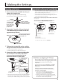
Mounting on the Stand
1. Use a commercially available drum key to
tighten the stopper bolt.
The stopper keeps the V-Cymbal from turning,
preventing the tangling of cables on the stand.
Attach the stopper
so that the bolt
is on the right-
hand side, from
the performer’s
perspective.
Bolt
Tighten the bolt
with a commercially
available drum key
Stopper
2. Attach the V-Cymbal, while positioning it
so the Roland logo is located on the side
opposite the performer.
Wing nut
Felt washer
Position the Roland logo
on the opposite side of
the playing area
3. Tighten the included felt washer and the
wing nut to obtain the desired movement.
* Use the included felt washer and wing nut.
* Double sounding may occur if the wing nut is loose.
4. Secure the cables in place with the cable
tie, and leave some slack in the cables
to ensure they are not pulled by the
movement of the V-Cymbal pads.
Secure the cable in place with
the cable tie
Leave some
slack in the
cable
Be sure to make this
small plastic hook
visible from you.
Wind a cable tie around
the pipe and tighten it in
order to not to slip.
Wind a cable tie around
a cable.
Insert the
small plastic
hook to a hole
to secure the cable
to the cymbal arm.
* Take care to ensure that the cables do not touch the V-Cymbal
pads and/ or the stand. A cable touching a V-Cymbal pad or a
stand may cause double sounding or other incorrect operation.
Connecting to a Percussion Sound Module
* To prevent malfunction and/or damage to speakers or other
devices, always turn down the volume, and turn o the power on
all devices before making any connections.
* Use the supplied connection cables (stereo) to make the
connections. If monaural cables are used, edge shots, bell shots,
and choke play cannot be supported.
Connect the L-shaped plug of the included cable to the
CY-13R/12C.
The CY-12C has no BELL OUTPUT jack. Make the
connection to the BOW/EDGE OUTPUT jack.
BELL
OUTPUT jack
BOW/EDGE
OUTPUT jack
CY-13R (Ride) CY-12C (Crash)
BOW/EDGE
OUTPUT jack
RD cable
(TD-9, TD-4)
To EDGE jack
(TD-20X, TD-20, TD-12)
CR1, 2 cable (TD-9, TD-4)
To CRASH 1, 2 jack
(TD-20X, TD-20, TD-12)
RDB cable (TD-9)
CR2 cable (TD-4) *1
To RIDE jack (TD-20X, TD-20, TD-12)
*1 Set the Crash 2 Usage parameter to “RIDE BELL.”
About three-way triggering (CY-13R only)
The CY-13R can take advantage of your percussion
sound module’s three-way triggering functionality
to allow you to play bow, bell, and edge
separately.
Connect the two outputs BOW/BELL and BOW/
EDGE to the percussion sound module at the
same time.
For details on the connection method and
settings, refer to the owner’s manual for your
percussion sound module.
* If you won’t be using the three-way triggering
functionality, connect the BOW/EDGE OUTPUT jack
(not both) to your percussion sound module.
* Although you’ll be able to play using the bow and bell
sections when connected to the BELL OUTPUT jack, you
won’t be able to use the choking technique.

6
Playing Methods
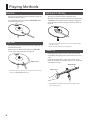
Bow Shot
This is the most common playing method, playing the
middle area of the cymbal.
It corresponds to the sound of the “head-side” of the
connected trigger input.
Edge Shot
This playing method involves striking the edge with the
shoulder of the stick.
When played as shown in the gure, the “rim-side”
sound of the connected input is triggered.
Edge sensor
* On the CY-13R, edge shots are possible when the connection is
made to the BOW/EDGE OUTPUT jack.
Bell Shot (CY-13R Only)
This playing method involves striking the bell.
On the CY-13R, when played as shown in the gure, the
“rim-side” sound of the connected input is triggered.
Strike the bell somewhat strongly with the shoulder of
the stick.
* Bell shots are possible when the connection is made to the CY-
13R’s BELL output.
* On the CY-12C, bell shots are not supported.
Choke Play
Choking (pinching) the cymbal’s edge with the hand
immediately after hitting the cymbal makes the sound
stop.
Choke the location of the edge sensor shown in the
gure. If you choke an area where there is no sensor, the
sound does not stop.
Edge sensor
Roland logo
* When ONLY using the BELL output of the CY-13R, the choke
function will not work.

7
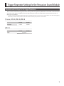
Trigger Parameter Settings for the Percussion Sound Module
TD series, SPD-30, SPD-SX, HPD-20
CY-12C CY-13R
Trig Type CY12C CY13R
HPD-10
CY-12C CY-13R
Type CY-12/14
Recommended Settings for the Trigger Parameters
These are the recommended trigger parameter settings when using the V-Cymbal with various models of sound module.
You may need to adjust the trigger parameters depending on how you’ve attached the V-Cymbal and the location at
which you’ve installed it.
* In order to use three-way triggering with the CY-13R, you must make settings on your percussion sound module to use its three-way triggering
functionality. For details on the procedure, refer to the owner’s manual for your percussion sound module.

8
For EU Countries

9
-
 1
1
-
 2
2
-
 3
3
-
 4
4
-
 5
5
-
 6
6
-
 7
7
-
 8
8
-
 9
9


Roland CY-12C Owner's manual
- Type
- Owner's manual
Ask a question and I''ll find the answer in the document
Finding information in a document is now easier with AI
Related papers
-
Roland TD-17KVX Installation guide
-
-
Roland CB-HPD-10 Owner's manual
-
-
-
Roland MDS-50K Installation guide
-
Roland TD-27KV Installation guide
-
-
-
Roland TD-9 Owner's manual