Page is loading ...

ADVANCED ENGINE MANAGEMENT INC.
2205 126
th
Street Unit A, Hawthorne, CA. 90250
Phone: (310) 484-2322 Fax: (310) 484-0152
http://www.aempower.com
Instruction Part Number: 10-3002 Rev B
2012 Advanced Engine Management, Inc
Page 1
Installation Instructions
for P/N 30-3002
Universal Water/Methanol
Injection Kit (without tank)
WARNING:
!
This installation is not for the electrically or mechanically
challenged! Use this system with EXTREME caution! If you are
uncomfortable with anything about this, please refer the
installation to an AEM trained tuning shop or call 800-423-0046
for technical assistance. You should also visit the AEM
Performance Electronics Forum at http://www.aempower.com
NOTE: AEM holds no responsibility for any engine damage that
results from the misuse of this product!
This product is legal in California for racing vehicles only and should never
be used on public highways.

Page 2
Specifications
• 200 PSI injection pump
• Progressive pump controller with “Boost Safe” feature
• 20-amp pump driver with over-current, over-voltage and under-voltage protection
• Error protection output with over-current, over-voltage and over-temperature protection
• System status LED indicator; shows pump duty cycle and system errors
• Pump open and short detection and indication; works even if the pump is off
• Test button that manually triggers pump
• Two dial pump speed control
• Battery voltage compensation
Parts List:
Quantity
Description
20 ft High Pressure ¼” Nylon Hose
1 200 PSI Pump With Hose Adapters
1 Progressive Injection Module
Mechanical Kit:
Quantity
Description
60
in
V
acuum Hose (
7/64"
)
36 in 1/4" High Temp Wire Wrap
6 in Edge Protector
1
3/16
”
T
ee Fitting
10 6” Zip Tie
4 Bolt, Hex Head, 8-32 x 1.5”
4 Screw, Pan Head #8 x 1.0"
4 Screw, Pan Head #6 x 0.5"
4 Nut, Nylock, 8-32
12
W
asher
, #8 x 3/4"
4 Washer, #8 x 7/16"
4 Washer, 5/16
1
5mm
Cockpit LED
2 Butt Connector, 14-16 AWG (blue)
9 Butt Connector, 18-22 AWG (red)
4 Ring Terminal, 14-16 AWD (blue)
1 1/4" Hose Routing Strip
Injector Nozzle Kit:
Quantity
Description
1 Stainless Injector Assy with Medium (315ml/min)Jet
1 Stainless Jet, Large (550ml/min)
2 Nylon Washer

Page 3
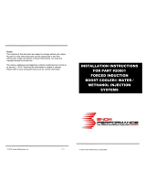
System Diagram
PLEASE DISREGARD THE CHECK VALVE IN THE ABOVE DIAGRAM. AN EXTERNAL
CHECK VALVE IS NO LONGER REQUIRED OR SUPPLIED WITH THIS INJECTION KIT.

Page 4
Pump and Tank Install
Find a suitable location to mount the pump and tank (not supplied). The tank should be
mounted such that it is below the injection point. The pump must be located in the same
area as the tank and should be mounted at or below the lowest fluid level height. Take note of
the direction of flow, indicated by the arrows on the pump body, when mounting the pump. If the
tank is mounted in the back of the vehicle the pump should be mounted in the back of the
vehicles as well and NOT in the engine bay.
Use four #8 sheet metal screws along with the 4 small washers or the #8-32 bolts and nylock
nuts to mount the pump. Pump may be mounted on exterior of vehicle but should be
mounted away from wheel wells or other areas where it will come into direct contact with
water or road debris. Pump failures that have clearly been caused by exposure to
water/mud/debris will not be covered under warranty. The pump can be mounted in any
position horizontally or vertically. Once the tank and pump are mounted, cut the appropriate
length of tubing needed to connect the outlet fitting on the tank to the inlet fitting on the pump.
Make sure there are no sharp bends in the tubing. Cut the tubing to length with a clean
perpendicular slice using a razor blade, making sure the ends are clean and square. Push in the
hose at the tank and pump to install. Make sure they are pushed in all the way and check with a
light tug on the hose. Secure the hose to the chassis using sections of the supplied hose routing
strip or with zip-ties.
Controller Install
Find a convenient location for the controller. The adjustment settings should remain in an
accessible location but still be protected from possible water incursion. If you need to extend
the wires to mount the controller use at least 14 AWG wire for the pump and controller ground
circuits and 18 AWG for the remainder. The controller is internally fused, no additional fuses
are required. Use the 2 supplied #6 screws to mount the controller.
LED Install
Find a suitable location in the driver’s line of sight to mount the status LED. Mount the LED and
run the wires to the controller. The LED indicates the operation of the controller. If the pump is
off and there are no errors the LED will be off. If there are no errors and the pump is on the LED
intensity will vary with the pump speed. If there are any errors they will be indicated by flashing
the LED.

Page 5
Boost Pressure Hose
Using the supplied vacuum tee and rubber hose, tap into a manifold pressure (boost) line
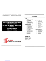
Variable Controller Installation
Fluid Level Switch (The switch has 2 black wires, the polarity is unimportant)
Black wire connects to Controller - Brown wire
Black wire connects to Controller - White wire
LED
Red wire connects to Battery Positive
Black wire connects to Controller - Gray Wire
Pump
Black wire connects to Controller - Orange wire.
Red wire connects to Battery Positive
Variable Pump Controller
Black wire connects to Battery Ground
Red wire connects to Battery Positive
Yellow wire connects to Arm switch or Key On power (+12V power to turn on the system)
Green wire (optional), Boost-Safe output for timing retard or boost dump solenoid; 1.7a Max
Blue wire (optional) 0-5vdc pressure signal for use with data logger or EMS;
.328v = 0psig, 5vdc = 38psig; PSI=8.1336 x Volts – 2.6678
Pump/Tank Flush
After all wires are hooked up, add water to the tank and with the hose pointed into a container,
press and hold the “TEST” push button on the controller module. The flow will start gradually
and increase to a steady amount. Repeat until you are sure the system is free of any debris that
way have been in the lines or tank. Drain the water out of the tank and refer to the next section
on installing the nozzle.

Page 6
Nozzle Selection and Assembly
This injection kit includes two different sized injection jets that cover a very large range of
horsepower levels. Use the following chart to select the appropriate jet for your power level.
The kit comes with one medium nozzle already preassembled.
HP Nozzle Selection
200-350 315 cc/min
350-600 550 cc/min
The nozzles are interchangeable and can be disassembled for cleaning. If you find excessive
debris in the screen, check your tank for contamination. When installing the screen it is only
necessary to be slightly tighter than finger tight. Do not over-tighten. The nylon washers are
reusable but a spare is included.
Nozzle Mounting
Select the location where the nozzle will be installed. Nozzle should be mounted such that it
is higher than the tank. Nozzle must be mounted before the throttle plate. Nozzle should also
be mounted after the MAF sensor if present. Nozzle must also be mounted after any
intercoolers. In most instances, mounting the nozzle 6-8” ahead of the throttle body provides an
excellent combination of air charge cooling and combustion control.
In most instances, the air charge piping can be drilled and tapped for 1/8” NPT to directly mount
the nozzle. If using thin walled tubing it’s suggested that a bung be welded to the piping.
Mounting hole should be tapped deep enough to allow the end of the nozzle to be nearly flush
with the interior of the intake once the nozzle is fully installed. The distance from the check
valve to the final injection point should be kept as short as practically possible. Make sure that
arrow on check valve body points toward the nozzle.

Page 7
Pump/System Check
The “TEST” push button on the controller module can be used to test the system. Press and
hold the button to activate the pump. The pump speed will gradually increase from zero to full
speed over 6 seconds and then stop. When the button is released the controller will return to
normal operation.
Add water to the tank and with the nozzle pointed into a container, press and hold the test
button. The flow will start gradually and increase to a steady amount. If this happens then your
system is connected properly. Check and repair any leaks. Drain the water out of the tank and
install the nozzle.
System Error Checking
Whenever a system error is encountered, the Boost-Safe output is enabled. All errors are
indicated by a flashing sequence of the status LED which can be determined by counting
flashes. Only one error can be counted with the higher priority at the top of this list:
1. Low Fluid indication
Trigger Condition: The fluid level in the water-methanol tank is below the float level.
The status LED will flash a count of one and repeat. The pump driver will continue to drive
the pump. If the level in the tank is enough to supply the pump with fluid, the controller will
function normally. Fluid flow may be lost in this condition.
2. Pump Driver Open
Trigger Condition: Open circuit between pump drive and battery voltage.
The status LED will flash a count of two and repeat. The pump driver will continue to drive
the pump. If the open is repaired the controller will function normally. Fluid flow may be lost
in this condition.
3. Pump Driver Shorted
Trigger Condition: Current exceeding 15A on the driver output.
The status LED will flash a count of three and repeat. The pump driver will turn off to protect
itself and automatically retry every second. If the short is removed the controller will function
normally. Fluid flow is lost in this condition.
4. Battery Voltage Out Of Range
Trigger Condition: Battery voltage is below 8.5V or above 16V.
The status LED will flash a count of four and repeat. The pump driver will turn off to protect
itself and automatically restart when the voltage returns to the normal range. Fluid flow is lost
in this condition.
5. Water-Methanol Controller
Trigger Condition: Water-methanol controller no longer functioning
The status LED will flash a count of five and repeat. The pump driver will turn off to protect
itself and automatically restart when the water-methanol controller works again. Fluid flow is
lost in this condition.

Page 8
Controller Settings
The controller will monitor the manifold pressure, battery voltage, potentiometer settings, push
button and error conditions. Two potentiometers are used to set the pump pulse width
modulation (PWM) rate. The “Start PSI” dial has a range from .5 psig (full counterclockwise
rotation) to 11 psig (full clockwise rotation). This is the manifold pressure that the pump will start
to operate. The “Full PSI” dial has a range of 6 psig (full counterclockwise rotation) to 38 psig
(full clockwise rotation). This is the manifold pressure that the pump will be running at full speed.
Additionally, the controller will automatically correct for battery voltage variations to give the
same flow.
Adjust the “Start PSI” value by setting the dial to approx 25% of the vehicles maximum boost.
Adjust the full-in value to your maximum possible boost (up to 38 PSIg of boost).
Error LED
The controller has an “ERROR” LED. This will mimic the operation of the cockpit LED. It will
flash out error codes as well as illuminate with varying intensity as a function of flow.
Short Circuit Testing
There are two modes of pump-driver short circuit protection available. One can detect a short at
any time but produces a slight buzzing in the pump. This should not be noticeable under most
conditions, but can be turned off if it is objectionable. If the less functional mode is chosen, then
a short can only be detected when the pump is running. Pressing and holding the “Test” button
while applying power toggles the mode. The change is acknowledged by a fast flashing (6
flashes and then repeats) of the status LED output and the on-board status LED. Once the
button is released the controller will continue to function normally. You can also tell what mode
has been selected by listening for the buzzing sound in the pump. Repeating this operation will
toggle between the two modes.
Boost-Safe Output (optional)
The progressive controller includes a Boost-Safe output (grounded when active) that activates
whenever the system is armed and runs out of fluid or an error code is flashing. The green wire
on the controller is the 1.7 amp switched ground. This wire can be hooked up to a solenoid that
will vent waste gate pressure when activated. Apply 12v to the other side of the solenoid (AEM
P/N 30-2400 or equivalent). This output can also be used to trigger a timing retard function in a
stand alone ECU or a CDI whenever the system runs out of fluid, thus protecting your engine.

Page 9
Engine Tuning
Water/methanol injection is generally not considered a bolt-on power adder for forced induction
gasoline applications. Engine tuning is usually required in order to maximize potential power
gain. Water/methanol injection allows for a more aggressive tune to be used while still using
pump gas as your base fuel.
Using a 50/50 mix of water/methanol is recommended for the best combination of air charge
cooling and detonation control. With conservative boost and timing, establish a base AFR that
is one point higher than your final target AFR. For example, if your final target AFR with
water/methanol injection is 11.0:1, set your base AFR to 12.0:1. Once the base AFR has been
set, start injecting water/methanol and adjust the injection flow rate to achieve your final target
AFR. For example, if before injection your base AFR is 12.0:1 and then during injection your
AFR drops to 10.5:1, reduce the water/methanol flow rate until your final target AFR is reached.
It is generally recommended that the flow rate of the injection system be changed in order to
reach your target AFR and NOT your primary fueling. Injection flow rate adjustments can be
made by changing your nozzle selection or by adjusting the “Start PSI” and “Full PSI” settings.
Once the injection flow rate is set to deliver your desired final AFR, boost and ignition timing can
be increased to take advantage of the additional air charge cooling and detonation control.
When injecting the correct amount, a 50/50 mix of water/methanol has been shown to provide
an effective octane of over 110 when using a base fuel of 91-93 octane pump gas. A properly
tuned water/methanol injection system will usually support a typical “race gas” engine tune.
Important Safety Notice Regarding Methanol
AEM strongly recommends that users never exceed a 50% methanol concentration when
using any AEM Water Methanol system or component.
All AEM Water/Meth injection systems and components (pump, lines, fittings, filter, flow sensor,
tank, and nozzles) are 100% chemically compatible with methanol. However, for safety reasons
we strongly recommend that users never use more than a 50% methanol concentration in our
systems.
Methanol is a toxic and highly flammable chemical. 100% Methanol ignites easily and burns
vigorously with an almost undetectable flame. Methanol can be absorbed through the skin and
even small amounts can cause blindness or even death. Using this fluid at high pressures,
without dilution, in an under-hood environment with nylon lines and push-to-connect fittings is
very unsafe. The performance advantages of using greater than 50% methanol concentrations
are small, if they exist at all. However, the safety issues are very real and far out weigh any
perceived benefit of running high concentrations of methanol.
Note: AEM holds no responsibility for any engine damage or personal injury that results
from the misuse of this product, including but not limited to injury or death caused by the
mishandling of methanol.

Page 10
Cold Weather Operation
A Water/Methanol mix will also lower the freezing point of the fluid. Below is a chart with
freezing points for different percentages of water/methanol mixtures.
Temperature
% of Methanol to Water
20 deg F 13
0 deg F 24
-15 deg F 35
-40 deg F 46
Maintenance
The injector nozzle should be cleaned periodically. Disassemble the nozzle and clean it with a
suitable cleaner until all debris is removed. If excessive contamination is found check the rest of
the system for the source.
AEM Electronics warranty
Advanced Engine Management Inc. warrants to the consumer that all AEM High Performance
products will be free from defects in material and workmanship for a period of twelve (12)
months from date of the original purchase. Products that fail within this 12-month warranty
period will be repaired or replaced at AEM’s option, when determined by AEM that the product
failed due to defects in material or workmanship. This warranty is limited to the repair or
replacement of the AEM part. In no event shall this warranty exceed the original purchase price
of the AEM part nor shall AEM be responsible for special, incidental or consequential damages
or cost incurred due to the failure of this product. Warranty claims to AEM must be
transportation prepaid and accompanied with dated proof of purchase. This warranty applies
only to the original purchaser of product and is non-transferable. All implied warranties shall be
limited in duration to the said 12-month warranty period. Improper use or installation, accident,
abuse, unauthorized repairs or alterations voids this warranty. AEM disclaims any liability for
consequential damages due to breach of any written or implied warranty on all products
manufactured by AEM. Warranty returns will only be accepted by AEM when accompanied by a
valid Return Merchandise Authorization (RMA number. Product must be received by AEM
within 30 days of the date the RMA is issued.
Please note that before AEM can issue an RMA for any electronic product, it is first necessary
for the installer or end user to contact the EMS tech line at 1-800-423-0046 to discuss the
problem. Most issues can be resolved over the phone. Under no circumstances should a
system be returned or a RMA requested before the above process transpires.
AEM will not be responsible for electronic products that are installed incorrectly, installed in a
non approved application, misused, or tampered with.
Any AEM electronics product can be returned for repair if it is out of the warranty period. There
is a minimum charge of $50.00 for inspection and diagnosis of AEM electronic parts. Parts used
in the repair of AEM electronic components will be extra. AEM will provide an estimate of repairs
and receive written or electronic authorization before repairs are made to the product.
/