
ES
PT
GB
NL
DE
FR
Table vitrocéramique
Recommandations et installation
Glaskeramisches Kochfeld
Gebrauchs-und Installationsanweisung
keramische kookplaat
Gebruiks- en installatievoorschriften
ceramic hob
Instructions for use and installation
Encimera vitrocerámica
Instrucciones de utilización y de instalación
Mesa vitrocerâmica
Instruções de utilização e de instalação
9953 8512.qxd 17/12/01 15:46 Page 1
Page is loading ...
Page is loading ...
Page is loading ...
Page is loading ...
Page is loading ...
Page is loading ...
Page is loading ...

7
FR
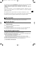
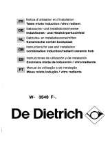
Raccordement électrique
Suivant votre modèle la table vous est livré soit :
Type H05 BBF
section 1,5 mm
2
à 5 conducteurs dont 1 pour la terre : jaune/vert
Le cordon doit être branchées sur le réseau par l’intermédiaire d’une prise de courant
conforme à la publication CEI83 ou d’un dispositif à coupure omnipolaire ayant une distan-
ce d’ouverture des contacts d’au moins 3 mm.
Si ce cordon d'alimentation est endommagé,ou si vous souhaitez le changer il ne
doit être remplacé que par votre Service Après-Vente car des outils spéciaux sont néces-
saires.
La table est livrée avec un boitier de raccordement
Le fusible de l’installation doit être de :
- 32 ampères pour les tables 3 ou 4 foyers.
- 16 ampères pour les tables 2 foyers.
Cet appareil est conforme aux directives européennes 73/23/CEE et 89/336/CEE
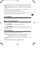
- 230 V monophasé
Branchez les 3 fils sur l’installation en respectant la couleur des fils
Bleu
Marron
Neutre
Terre
Phase
Noir
Vert / jaune
Neutre
Terre
Phase 2
Phase 1
Vert / jaune
N L
N
L1
L2
NOTA
séparer les 2 fils
de phase L1, L2
avant
branchement
Marron
Bleu
Noir
Neutre
Terre
Phase
N L
Bleu
Noir
-
400V 2N triphasé
Branchez les 4 fils sur l’installation en respectant la couleur des fils
Avec un cordon d’alimentation
L2
L3
L1
400V 3 Ph
(Suisse)
9953 8512.qxd 17/12/01 15:46 Page 7

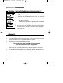
8
Ces tables doivent être branchées sur le réseau par l’intermédiaire :
- D’un cordon d’alimentation Type H05 BBF à 3 conducteurs de 2,5 mm
2
ou 5
conducteurs de 1,5 mm
2
(dont 1 pour la terre : jaune/vert) Résistant à la températu-
re type BBF
- D’une prise de courant conforme à la publication CEI83 ou d’un dispositif à cou-
pure omnipolaire ayant une distance d’ouverture des contacts d’au moins 3 mm.
Le fusible de l’installation doit être de :
- 32 ampères pour les tables 3 ou 4 foyers.
Cet appareil est conforme aux directives européennes 73/23/CEE et 89/336/CEE
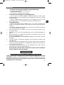
Avec un boitier de raccordement
2
4
1
5
3
2
4
1
5
3
230V
400V2N
2
4
1
5
3
2
4
1
5
3
400V3N
230V2-2N
L1
N
L1
N
L2
L1
L2
L3
N
L1
L2
N1
N2
2
4
1
5
3
230V3
L1
L2
L3
9953 8512.qxd 17/12/01 15:46 Page 8
Page is loading ...
Page is loading ...
Page is loading ...
Page is loading ...
Page is loading ...
Page is loading ...
Page is loading ...

16
Diese Kochfelder müssen an das Stromnetz wie folgt angeschlossen werden :
- Durch einen Anschlußkabel (Typ H05 BBF) : mit 3 Stromleiter von 2,5 mm
2
oder 5
Stromleiter von 1,5 mm
2
(davon 1 für die Erdung : gelb/grün) hitzebeständig, typ
BBF
- Mit einer nach CEI83 Vorschrift entsprechenden Steckdose oder durch eine allpo-
lige Trenneinrichtung mit mindestens 3 mm Kontaktöffnungsweite.
Stromabsicherung
- 32 A mpere für die Kochfelder mit 3 oder 4 Kochzonen.
Dieses Gerät entsricht den EWG-Richtlinien 73/23/CEE und 89/336/CEE
Mit einer Anschlußklemme
2
4
1
5
3
2
4
1
5
3
230V
400V2N
2
4
1
5
3
2
4
1
5
3
400V3N
230V2-2N
L1
N
L1
N
L2
L1
L2
L3
N
L1
L2
N1
N2
2
4
1
5
3
230V3
L1
L2
L3
9953 8512.qxd 17/12/01 15:46 Page 16
Page is loading ...

18
Keuze
•
Elektrische kookpannen
Gebruik pannen met een vlakke bodem :
- van roestvrij staal met dikke driemetalen of “sandwich”
bodem
- van aluminium met dikke gevlochten (gladde) bodem
- van geëmailleerd staal.
•
De panbodems die te ruw zijn, kunnen stoffen vasthouden die vlekken of
krassen op de kookplaat kunnen veroorzaken
Tip
•
Verzeker u ervan dat de onderkant van de pan en het kookvlak schoon en
droog zijn.
•
Gebruik een pan die groot genoeg is en stel op de juiste manier in om over-
koken en spatten te voorkomen.
•
Gebruik een pan met
een bodem van dezelfde of grotere diameter
als die van de verwarmingsplaat.
Plaats de pan midden op de verwarmingsplaat die het meest overeenkomt
met de afmeting hiervan.
•
Staan er meerdere pannen op de kookplaat dan ook rekening houden met
de afmeting van de stelen.
Panwerk
9953 8512.qxd 17/12/01 15:46 Page 18
Page is loading ...
Page is loading ...

21
NL
Inbouw in het werkblad
40 mini
40 mini
40 mini
Uitsnijden
Snij een opening met de nodige afmetingen uit het werkblad.
Meet het maatgetal van 40 mm vanaf de muur en de zijwanden (achter- of/en zijkanten).
Bescherming van de werkblad opening :
Vooral vezelplaat dat gebruikt wordt voor werkbladen neemt vrij snel vocht op.
Behandel daarom de opening in het werkblad met een waterafstotend materiaal (verf of
speciale kit) om deze te beschermen tegen eventueel vocht of condensatie onder het
werkblad.
Fixation :
xxxxxx
265/560/750
490
afmeting in mm
9953 8512.qxd 17/12/01 15:46 Page 21

22
De plaat kan rechtstreeks van bovenaf in het werkblad boven de oven worden geschoven.
(minimum afstand 10 mm).
De glas keramische platen zijn uitgerust met warmte beveiligingen, die deze beschermen
bij oververhitting en in “stand by” zet tot volledige afkoeling van de elementen.
Boven een oven
Kies uw installatie
❥ boven een leeg kastje of lade
❥ boven een oven
vide
sanitaire
80mm
AVANT MEUBLE
Boven een leeg kastje of lade
10 mm
VOORKANT
KASTJE
lege ruimte
9953 8512.qxd 17/12/01 15:46 Page 22

23
NL
Elektrische aansluiting
Al naar gelang uw model wordt de kookplaat geleverd met :
Van het type H05 BBF doorsnede 1,5 mm
2
met 5 geleiders waarvan één met
aarding: geel/groen.
De snoer dient aangesloten te worden op het stroomnet d.m.v. één met de EEG publikatie
7 overeenstemmend stopcontact of met een omnipolaire stroomonderbreker met een
openingsafstand van de contactpunten van minstens 3 mm.
Daar speciaal gereedschap nodig is voor het vervangen van deze snoer dient u
zich, wanneer deze beschadigd is of indien u een andere wenst, uitsluitend te richten tot
uw Service Dienst.
De kookplaat wordt geleverd met een aansluitingsdoos.
De smeltverzekering van de installatie:
- 32 ampère voor kookplaten met 3 of 4 verwarmingsplaten.
- 16 ampère voor kookplaten met 2 verwarmingsplaten.
Dit apparaat stemt overeen met de Europese richtlijnen 73/23/EEG en 89/336/EEG
- 230 V eenfasig
Sluit de 3 draden aan op de installatie en zorg er voor dat de kleuren
van de draden met elkaar overeenkomen.
Bruin
Blauw
Neutraal
Massa
Fasig
Zwart
Groen /geel
Neutraal
Massa
Fasig 2
Fasig 1
Groen /geel
N L
N
L1
L2
Nota :
vóór het aansluiten de
2 fase draden L1. L2
van elkaar scheiden
Blauw
Bruin
Zwart
Neutraal
Massa
Fasig
N L
Blauw
Zwart
- 400V 2N triphasé
Branchez les 4 fils sur l’installation en respectant la couleur des fils
Een snoer
L2
L3
L1
400V 3 Ph
(Suisse)
9953 8512.qxd 17/12/01 15:46 Page 23

24
Deze kookplaten dienen aangesloten te worden op het stroomnet door middel van :
- een snoer: met 3 geleiders van 2,5 mm2 of geleiders van 1,5 mm2 (waarvan 1
voor de massa: geel/groen). hittebestendig, type BBF
- een contactdoos conform de EEG publikatie 7 of met een omnipolaire
stroomonderbreker met een openingsafstand van de contactpunten van minstens 3 mm.
De smeltverzekering van de installatie:
- 16 ampère voor kookplaten met 2 verwarmingsplaten.
Dit apparaat stemt overeen met de Europese richtlijnen 73/23/EEG en
89/336/EEG
een aansluitingsdoos
2
4
1
5
3
2
4
1
5
3
230V
400V2N
2
4
1
5
3
2
4
1
5
3
400V3N
230V2-2N
L1
N
L1
N
L2
L1
L2
L3
N
L1
L2
N1
N2
2
4
1
5
3
230V3
L1
L2
L3
9953 8512.qxd 17/12/01 15:46 Page 24

25
GB
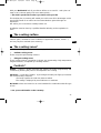
With your De Dietrich hob all your dishes will be so successful : seal a piece of
meat or let is simmer gently, boil some water quickly ......
....This hob is produced to seduce you and to ease your life.
This booklet plus a summary will enable you to discover all its advantages and to
get the full benefit of our advice and recommendations gained through our
experience.
We advice you to read them carefully before use.
Installation must be done by a qualified installer adhering to the regulations in
force.
The cooking surface
Ceramic glass, resistant to harsh conditions of application (shocks, friction ...)
and very simple to maintain (see summary)
The cooking zones*
All radiant or halogen cooking zones are equipped with temperature limiters.
•
Radiant cooking zones
These comprise rapid heating resistors.
•
Halogen cooking zones
These comprise lamps (containing a halogen gas regenerating a high temperature
tungsten filament), completed by a heating resistor.
Controls *
Handle : controls a power measurer that adjusts the power progressively and
continuously allowing the power to be adapted to the cooking.
Electronic : “Capacitive” buttons, by touching them with your finger you transmit
the corresponding command.
One beep signifies the order has been recorded.
The setting is displayed by small indicators or readouts.
No handle : these are located on an oven intended for combination with this type
of hob.
* See your model details on the summary
9953 8512.qxd 17/12/01 15:46 Page 25

26
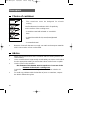
Choice of container
•
The containers must be designed for electric
cooking
Use flat-bottomed containers which lie perfectly
on the surface of the cooking zone :
- in stainless steel with trimetal or “sandwich”
base
- in aluminium with thick (smooth) straightened
base
- in enamelled steel
•
Bottoms of utensils that are too rough can retain and transport materials
which cause stains or lines on the table.
Advice
•
Make sure that the bottom of the container and the cooking surface are
clean and dry.
•
Use a container that is large enough to take what you want to cook and se
lect the appropriate setting to ensure that it does not boil over or splash.
•
Use the correct size container :
the diameter of the bottom must be equal to or in excess of the
diameter of the electric cooking zone.
Centre the container on the cooking surface that is best suited to its
size.
•
To avoid any problems with the handles of pans or containers, respect
the built-in dimensions given.
Saucepans
9953 8512.qxd 17/12/01 15:46 Page 26

27
GB
•
A higher power setting is required when :
- there is a large amount in your container
- the cooking container is not covered
- a glass or ceramic container is used.
•
A lower power setting is required when :
- the food you are cooking burns easily (starting with a setting lower than the
one indicated in the table opposite, increasing it as necessary)
- it boils over (remove the cover or take off the container, then reduce the
setting)
•
Saving energy :
To finish off the cooking, depress the stop button and allow the container to
stand using the residual heat (you will save energy in this way)
Use a cover as often as possible to reduce heat loss through evaporation.
•
Never leave a pan or container holding oil or hot fat on the cooking areas
unsupervised.
•
Avoid staring at the halogen lamps of the cooking cooking zone
•
When connecting electrical appliances to plugs located nearby, make sure
that the supply cable does not contact the hot areas.
Do not store your MAINTENANCE or INFLAMMABLE products in the area
located under your cooking table.
•
Do not place plastic or aluminium leaf objects on the cooking surfaces
when they are still hot.
•
The ceramic surface is very resistant but is not, however, unbreakable ;
avoid impacts from the containers, it must not be used as a work surface
for anything at all
•
Over the long term, friction from the containers can result in deterioration to
the patterns on the ceramic tops.
These defects, which do not result in non functioning or an inability
to be used, are not covered by the guarantee.
Do not place any HOT CONTAINER on your hob after cooking
If a crack appears in the glass surface, deconnect the appliance immedia-
tely from the electric power source, removing the fuses or actuating the circuit-
breaker. Do not use any part of the hob before a new
ceramic cooking zone has been fitted.
NOTE :
Advice
9953 8512.qxd 17/12/01 15:46 Page 27

28
To the installer
In your capacity as a specialist, you alone are qualified to install and adjust De
Dietrich appliances.
It is for this reason that our warranty applies solely and exclusively to appliances
that have been installed and adjusted by you in accordance with local regulations.
Non respect of this condition is the responsibility of the installer and annuls any
responsibility by De Dietrich.
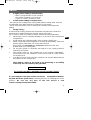
Protection against over-heating : according to type Y. selon CEI 335-2-6
Precautions
Please respect the following points scrupulously :
❥ The walls above the work surface and in the immediate vicinity of the hob must
be heat resistant.
❥ The laminated worktops and the adhesive fixing the same must be heat resistant
to avoid any deterioration.
❥ The space of fresh air required under and behind the hob is to improve its
reliability by guaranteeing air-cooling in all built-in configurations.
❥ The hob must not be installed above a dishwasher, a washing machine, a
fridge or a freezer.
When your hob is connected to the mains power and after a longer power failures, a indication lights
up on the control panel. This indication goes off automatically afer 30 seconds, or the first pression
of any buttonon the control panel. This is a normal display and is reserved for the after sale service.
Under no circumstances the user do not take this in consideration.
9953 8512.qxd 17/12/01 15:46 Page 28

29
GB
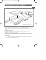
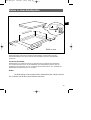
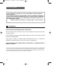
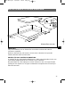
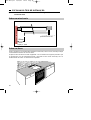
Built into the work surface
40 mini
40 mini
40 mini
Cutting-out
Make a cut to the dimensions required in the work surface.
There must be 40 mm minimum between the wall and the sides (back and/or
sides).
Protecting the cut-outs :
The chipboard used in the production of the work surfaces swells up relatively
quickly on contact with humidity.
Apply a varnish or a specialised adhesive to the edge of the cut-out to protect it
from the damp or condensation that can occur under the working surface.
Fixation :
265/560/750
490
dimensions in mm
9953 8512.qxd 17/12/01 15:46 Page 29

30
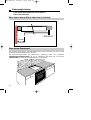
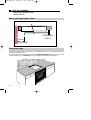
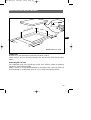
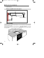
The hob can be directly built into the work surface on top of the oven in a high
position (minimum gap 10 mm).
The ceramic hobs are equipped with thermal safety units which protect them
against over-heating and “monitor” the components until cooled
On top of an oven
Selecting your installation
❥ on top of an empty unit or drawer
❥ on top of an oven
vide
sanitaire
80mm
AVANT MEUBLE
On top of an empty unit or drawer
10 mm
UNIT FRONT
Ventilation
space
9953 8512.qxd 17/12/01 15:46 Page 30

31
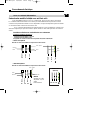
GB
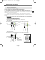
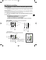
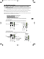
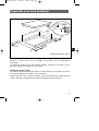
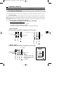
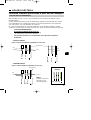
Electrical connection
According to your model, your hob is supplied to you either :
Model H05 BBF section 1.5 mm2 with 5 conductors, 1 of which for earth : yellow /
green.
The cable must be connected to the mains by a plug complying with publication CEI83 or
by an omnipolar switching device with a minimum contact opening gap of 3 mm.
If this power cable is damaged or if you wish to change it, it may only be replaced by your
After Sales Service as special tools are necessary.
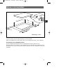
The hob is supplied with a junction box
The installation fuse must be :
- 32 amps for hobs with 3 or 4 cooking zones
- 16 amps for hobs with 2 cooking zones
This appliance meets European Directives 73/23/CEE and 89/336/CEE
- 230 V monophase
Connect the 3 wires to the installation respecting the colour of the wires
Brown
Blue
Neutral
Earth
Phase
Black
Green / Yellow
Neutral
Earth
Phase 2
Phase 1
Green / Yellow
N L
N
L1
L2
NOTE : Separate
the 2 wires phase
L1, L2 before
connection
Brown
Blue
Black
Neutral
Earth
Phase
N L
Blue
Black
- 400 N 2N three-phase
Connect the 4 wires to the installation respecting the colour of the wires
With a power cable
L2
L3
L1
400V 3 Ph
(Suisse)
9953 8512.qxd 17/12/01 15:46 Page 31

32
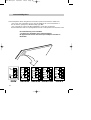
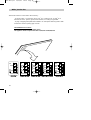
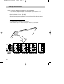
These hobs must be connected to the mains by :
- A supply cable : 3 conductors of 2.5 mm
2
or 5 conductors of 1.5 mm
2
(1 of
which is for earth : yellow / green) heat resistant, according to type BBF
- A plug complying with publication CEI83 or an omnipolar switching device with
a minimum contact opening gap of 3 mm
The installation fuse must be :
- 32 amps for hobs with 3 or 4 cooking zones
This appliance meets European Directives 73/23/CEE and 89/336/CEE
With a junction box
2
4
1
5
3
2
4
1
5
3
230V
400V2N
2
4
1
5
3
2
4
1
5
3
400V3N
230V2-2N
L1
N
L1
N
L2
L1
L2
L3
N
L1
L2
N1
N2
2
4
1
5
3
230V3
L1
L2
L3
9953 8512.qxd 17/12/01 15:46 Page 32
Page is loading ...
Page is loading ...
Page is loading ...
Page is loading ...

37
ES
Empotrado en la zona de trabajo
40 mini
40 mini
40 mini
Corte
Efectúe un corte en la zona de trabajo de acuerdo con las dimensiones
necesarias.
La distancia mínima de 40 mm deberá medirse a partir de la pared y de las
paredes laterales (por detrás y/o a los lados).
Protección de los cortes :
La madera aglomerada utilizada para la confección de las encimeras se hincha
con relativa rapidez al contacto con la humedad.
Aplique sobre el canto cortado un barniz o una cola especial para protegerla del
vapor o del agua condensada que pudiese formarse bajo la encimera.
xxxxxx
265/560/750
490
dimensiones en mm
9953 8512.qxd 17/12/01 15:46 Page 37
Page is loading ...

39
ES
Conexión eléctrica
Según el modelo de encimera, se le habrá entregado :
Tipo H05 BBF de sección 1,5 mm
2
con 5 conductores de los cuales el amarillo y verde va conec do
a la toma de tierra.
El cable deberá conectarse a la red mediante una toma de corriente que se ajuste a la recomendación
CEE 7 o un dispositivo interruptor omnipolar con una distancia de abertura entre contactos de al
menos 3 mm.
Si el cable de alimentación se dañase o si desea cambiarlo, sólo podrá ser sustituido por su Servicio
Post-Venta pues son necesarias herramientas especiales.
La encimera se entrega con una caja de conexiones
El fusible de instalación deberá ser de:
. - 32 amperios para las encimeras de 3 o 4 fuegos
. - 16 amperios para las encimeras de 2 fuegos
Este aparato se ajusta a las directivas europeas 73/23/CEE y 89/336/CEE
- 230 V monofásico
Conectar los 3 hilos a la instalación respetando el color de los hilos.
Moreno
Azull
Neutro
Tierra
Fase
Negro
Verde/amarillo
Neutr0
Tierra
Fase 2
Fase 1
Verde/amarillo
N L
N
L1
L2
NOTA
Separar los dos hilos
de fase L1 y L2 antes
de proceder a su
conexión.
Moreno
Azull
Negro
Neutr0
Tierra
Fase
N L
Azull
Negro
- 400V 2N trifásico
Conectar los 4 hilos a la instalación respetando el color de los hilos.
Un cable de alimentación
L2
L3
L1
400V 3 Ph
(Suisse)
9953 8512.qxd 17/12/01 15:46 Page 39

40
Estas encimeras deberán conectarse a la red mediante :
- Un cable de alimentación de 3 conductores de 2,5 mm
2
o de 5
conductores de 1,5 mm
2
(de los cuales el amarillo/verde va conectado a
tierra) resistento al calor, tipo BBF
- Una toma de corriente que se ajuste a la recomendación CEI83 o un
dispositivo interruptor omnipolar con una distancia de abertura entre
contactos de al menos 3 mm.
El fusible de instalación deberá ser de:
- 32 amperios para las encimeras de 3 o 4 fuegos
- Este aparato se ajusta a las directivas europeas 73/23/CEE y 89/336/CEE
Una caja de connexiones
2
4
1
5
3
2
4
1
5
3
230V
400V2N
2
4
1
5
3
2
4
1
5
3
400V3N
230V2-2N
L1
N
L1
N
L2
L1
L2
L3
N
L1
L2
N1
N2
2
4
1
5
3
230V3
L1
L2
L3
9953 8512.qxd 17/12/01 15:46 Page 40
Page is loading ...
Page is loading ...
Page is loading ...
Page is loading ...
Page is loading ...
Page is loading ...
Page is loading ...
Page is loading ...
Page is loading ...
Page is loading ...
-
 1
1
-
 2
2
-
 3
3
-
 4
4
-
 5
5
-
 6
6
-
 7
7
-
 8
8
-
 9
9
-
 10
10
-
 11
11
-
 12
12
-
 13
13
-
 14
14
-
 15
15
-
 16
16
-
 17
17
-
 18
18
-
 19
19
-
 20
20
-
 21
21
-
 22
22
-
 23
23
-
 24
24
-
 25
25
-
 26
26
-
 27
27
-
 28
28
-
 29
29
-
 30
30
-
 31
31
-
 32
32
-
 33
33
-
 34
34
-
 35
35
-
 36
36
-
 37
37
-
 38
38
-
 39
39
-
 40
40
-
 41
41
-
 42
42
-
 43
43
-
 44
44
-
 45
45
-
 46
46
-
 47
47
-
 48
48
-
 49
49
-
 50
50
-
 51
51
-
 52
52


De Dietrich WW3536E1 Owner's manual
- Type
- Owner's manual
Ask a question and I''ll find the answer in the document
Finding information in a document is now easier with AI
in other languages
- français: De Dietrich WW3536E1 Le manuel du propriétaire
- español: De Dietrich WW3536E1 El manual del propietario
- Deutsch: De Dietrich WW3536E1 Bedienungsanleitung
- Nederlands: De Dietrich WW3536E1 de handleiding
- português: De Dietrich WW3536E1 Manual do proprietário
Related papers
-
 De Dietrich WM3019E2 Owner's manual
-
 De Dietrich WM3559E2 Owner's manual
-
 De Dietrich WN3869E1 Owner's manual
-
 De Dietrich WE5349E1 Owner's manual
-
 De Dietrich WE5859E1 Owner's manual
-
 De Dietrich WE5659E11 Owner's manual
-
 De Dietrich WM0459D1 Owner's manual
-
 De Dietrich 9941MOP Owner's manual
-
 De Dietrich WE5659E3 Owner's manual
-
 De Dietrich WM3549E2 Owner's manual


Other documents
-
Groupe Brandt BV62X Owner's manual
-
-
Bosch 3VC730XC/01 User manual
-
Bogen BBF User manual
-
Groupe Brandt WN0576D1 Owner's manual
-
-
-
-
-